
Related Manuals for Kaysun KCCT-64 I (B)


Summary of Contents for Kaysun KCCT-64 I (B)
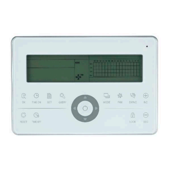
- Page 1 INSTALLATION AND OWNER’S MANUAL Centralized Controller KCCT-64 I (B) IMPORTANT NOTE Thank you very much for purchasing our product. Before using your unit, please read this manual carefully and keep it for future reference.
-
Page 2: Table Of Contents
CONTENT 1. Installation part ……………………. 1.1 List of fittings and installation components ……………………. 1.2 Notes to installation ……………………. 1.3 Installation procedure ……………………. 1.4 Wiring procedure ……………………. 1.5 Safety precautions ……………………. 1.6 System wiring instruction ……………………. 2. Operation part ……………………. 2.1 Function instructions ……………………. -
Page 3: Installation Part
INSTALLATION PART... -
Page 4: List Of Fittings And Installation Components
1.1 L ist of fittings and installation components 1. Packing box list of indoor unit centralized controller KCCT 64 I. Please check whether the assemblies are complete. Name Quantity Remarks Indoor unit centralized ____________ Fastening cross groove pan GB845/ST3.9*25-C- head H(S) self-tapping Fastening plastic expansion... -
Page 5: Notes To Installation
1.2 Notes to installation Notes to installation 1) Directly insert 220V~50Hz power into the wiring socket L, N terminals of centralized controller. 2) Do not lay the signal wire and the power wire of the centralized controller in the same power wire pipe, there should be 300~500mm distance between two pipes. - Page 6 Insert the flathead screwdriver into the concave on the upper side of the box, and rotate slightly to open the upper cover (3 places). Fix the screws of the centralized controller (GB845/ST.3 9*25) Base Dial code Address dial code Front cover Dial code position Address range Fig.
-
Page 7: System Wiring Instruction
1.4 System wiring instruction Network air conditioner wiring diagram (two types for indoor unit: one is the main control board needs an external network interface module; the other is network interface module is built in the main control board). RS232 pin buckle: insert the COM port of computer Electronic control box Fig.1.4 Wiring diagram... - Page 8 Note The RS485-to-RS232 module in the wiring diagram and the wires are put into use only when the network system needs to be connected with the computer. One computer can be connected with 16 centralized monitors at most. Namely a maximum of 16X64=1024 indoor units can be connected.
- Page 9 1.6 System wiring instruction. 1) Wiring diagram of b u i l d i n g network air conditioning system. (a) Wiring diagram with good communication effect (recommended) (b) Wiring diagram with poor communication effect (not recommended because it ma y lead to poor communication) 2) System wiring diagram of centralized monitoring and indoor unit of air conditioner.
-
Page 10: Operation Part
OPERATION PART... -
Page 11: Function Instructions
2.1 Function instructions 1. Centralized controller is used for network air-conditioner to realize centralized controlling and data querying. Each centralized controller can be connected to maximum 64 indoor units, through 485 communications can to form an air conditioner LAN and realize the centralized monitoring network in the air conditioner. -
Page 12: Status Indication
2.3 Function instructions 2.3.1 State indication 1. LED state indication lamp 1) Normal state 1- Normally on The LED indication lamp will be normally on when any one of the following situations display: a) In the centralized controller network, one or more air conditioners are under operating state. b) Through the centralized controller’s operation, when the centralized controller is sending order to the air conditioner, LED indication lamp will be normally on. -
Page 13: All Kinds Of Locking Status
of the centralized controller is turned on, all air conditioners in the network of the centralized controller will start up compulsorily. By default, they will run in the cooling mood. The startup and shutdown operations of the centralized controller and computer and all functional modules will be disabled (only the command of startup is sent to the air conditioner without affecting operation of the remote controller after startup) until the forced-on switch is turned off. - Page 14 only can choose the mode which has not conflict with locking mode. 2) Operation Can set the heating mode locking or cooling mode locking. Under mode locking state, if set the new mode locking, it must be unlocking first, then can operate the new mode locking.
- Page 15 One or more air conditioners under ON state (include timing process of timing ON and OFF) “ ” key only has short press function. Only send the OFF order to the air conditioners with ON state, not for OFF state units. Activate the power off memory function, to record the current operating state of all air conditioners.
-
Page 16: Instruction Of Electric Control Function
2.4 Instruction of electric control function Keys of centralized controller... - Page 17 2.4.1 Key operation instruction 1. Query key “ ” Any time when you press the key, the selected operation mode is to query the operation status of the air conditioner. By default, the first in-service air conditioner will be queried. 2.
- Page 18 9. Rightward key “ ” In the main page, press this key “ ” to enter the query mode. By default, it is the first in-service air conditioner. In any other time, press this key “ ” will select the next in-service air conditioner. In the setting mode, if selected all the air conditioners to operate, this key “...
- Page 19 13. Reduce key “ ” 1) Query mode Press this “ ” key, display the data of the previous page. If it is now in the first page, press the key “ ” again and the last page will be displayed.
- Page 21 2.4.2 LCD instruction 1. General display data entries 1) General display data is displayed in all display pages. 1- Under the interconnected control of the computer or gateway, the data is displayed in graphic . Otherwise, no data is displayed. 2- If the centralized controller is connected with the functional module for communication, the data is displayed in graphics .
- Page 22 a. The array of the liquid crystal display is composed of 4X16 grids, and each grid is composed of two blocks of different sizes (as shown in the above figure). The status indication table is as follows˖ Status Constantly on Slow blink Fast blink Not bright Object Big black...
- Page 23 Description of the query page Fig 2.6 The example diagram of the query page ŚThe LCD display shows the query page, and the air conditioner with the address of 01 is being queried. śMode of the air conditioner with the address 01 is: Cooling, strong air, swing on, indoor temperature 22°C,set temperature 20°C, cooling mode “lock”.
- Page 24 Fault page display description Fig 2.8 The example diagram of fault page 1-Query the air conditioner with the address of 08 in the query page. 2-The air conditioner with the address of 08 is faulty, and fault code is 08. The big black dot below (00+,08) blinks.
- Page 25 00 01 0² 03 04 0‘ 06 0‘ 08 09 10 11 1² 13 14 1‘ 3²+ a. Function selection b. Parameter selection c. Reminding d. “Set successfully” reminding Fig 2.9 Filter net in addition to the dust function involves of show a contents 2) Function setting Ś...
-
Page 26: Error Code Table
2.4.4 Error code table Fault code Fault content Description Other faults Water level detection faults Cleaning fault Inverter module protection Over-current of compressor(4 times) Fault of communication between main board and display board Air speed detection out of control EEPROM error Zero crossing detection error Outdoor unit fault protection T2A sensor fault... -
Page 27: Technical Index And Requirements
2.5 Technical indices and requirements 1. EMC, EMI comply with the CE certification requirements. 2. Electrical safety comply with GB4706.32-2004, GB/T7725-2004.
Need help?
Do you have a question about the KCCT-64 I (B) and is the answer not in the manual?
Questions and answers