
Related Manuals for Kaysun KC-02.1 H


Summary of Contents for Kaysun KC-02.1 H
- Page 1 OWNER’S MANUAL Wired controller KC-02.1 H IMPORTANT NOTE Thank you very much for purchasing our product. Before using your unit, please read this manual carefully and keep it for future reference.
-
Page 2: Table Of Contents
CONTENTS 1. Safety Precautions ................. 3 2. Model and Specification ................ 4 3. Buttons And Their Functions ..............5 4. Installation ....................6 5. Wiring figure ..................7 6. Preparation before installation ............11... -
Page 3: Safety Precautions
1. Safety Precautions The following contents are stated on the product and the operation manual, including usage, precautions against personal harm and property loss, and the methods of using the product correctly and safely. After fully understanding the following contents (identifiers and icons), read the text body and observe the following rules. -
Page 4: Model And Specification
2. Model And Specification Model KC-02.1 H Power Supply Voltage 5.0V DC -5°C~43°C Ambient Temperature Range Ambient Humidity Range RH40%~RH90%... -
Page 5: Buttons And Their Functions
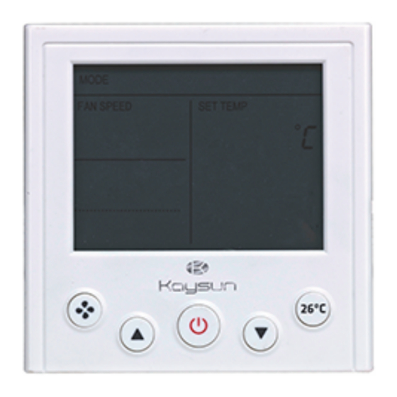
3. Buttons And Their Functions KC-02.1 H is a Mode-button Hidden Wired Controller. Designed with succinct appearance can be apply for hotel, hospital and school etc. (1) ON/OFF button Press the ON/OFF button can turn on or turn off air conditioner. -
Page 6: Installation
4. Installation 4.1 Installation methods ※ Principle diagram of wired controller ※ Installation instruction figure Attached connecting wires for the display panel 4-core shielding wire Display panel embedded in the wall 4-core shielding wire embedded in the wall... - Page 7 Notes: 1) Over tighten the screw would cause the rear covers deformed and LCD damage. 2) When installation, please maintain the screws and wired controller at the same height level without deformed. 3) When installation, please reserve a certain length of wired controller connectivity cable for future maintenance to take off the wired controller.
-
Page 8: Wiring Figure
5. Wiring figure 1) Wiring figure of the wired controller connect with the four-way cassette type indoor unit. Indoor unit electric Plane of indoor unit controlling box Electric controlling boxs’ plug CN10 Main board 10-core connecting wire group Display panel 4-core shield cable Back of the wired remote Controller 2) Wiring figure of the wired controller connect with the courtyard-style duct type indoor... - Page 9 3) Wiring figure of the wired controller connect with the high-static pressure duct type indoor unit. Indoor unit electric controlling box Electric controlling boxs’ plug CN10 Main board Display panel A B C D Back of the wired remote controller 4-core shield cable 4) Wiring figure of the wired controller connect with the wall hanging type indoor unit.
- Page 10 5) Wiring figure of the wired controller connect with the stand-hanging type indoor unit. Indoor unit electric controlling box Plane of indoor unit Electric controlling boxs’ plug CN10 Main board 10-core connecting wire group Display panel 4-core shield cable Back of the wired remote controller A B C...
-
Page 11: Preparation Before Installation
6. Preparation before Installation Make sure the following pasts has been prepared. Name QTY. REMARK Wired controller — Installation & owner’s manual — For installing the wired controller on the M4×25 Cross head screwdriver electrical box. For installing the wired controller on the Installation and owner's manual electrical box.
Need help?
Do you have a question about the KC-02.1 H and is the answer not in the manual?
Questions and answers