Sign In
Upload
Download
Table of Contents
Contents
Add to my manuals
Delete from my manuals
Share
URL of this page:
HTML Link:
Bookmark this page
Add
Manual will be automatically added to "My Manuals"
Print this page
×
Bookmark added
×
Added to my manuals
Manuals
Brands
Kikusui Manuals
Test Equipment
PFX2000 Series
Operation manual
Kikusui PFX2000 Series Operation Manual
Charge/discharge battery test system
Hide thumbs
1
2
3
4
5
6
7
8
Table Of Contents
9
10
11
12
13
14
15
16
17
18
19
20
21
22
23
24
25
26
27
28
29
30
31
32
33
34
35
36
37
38
39
40
41
42
43
44
45
46
47
48
49
50
51
52
53
54
55
56
57
58
59
60
61
62
63
64
65
66
67
68
69
70
71
72
73
74
75
76
77
78
79
80
81
82
83
84
85
86
87
88
89
90
91
92
93
94
95
96
97
98
99
100
101
102
103
104
page
of
104
Go
/
104
Contents
Table of Contents
Bookmarks
Table of Contents
Power Requirements of this Product
Safety Symbols
Safety Precautions
Table of Contents
Preface
Chapter 1 Setup
Checking the Package Contents
Installation
Precautions Concerning Installation Location
Rack Mounting
Precautions When Moving the Product
Connecting the Power Cord
Grounding
Installing and Removing Charge/Discharge Power Supply Units
Combinations of Unit Frames and Charge/Discharge Power Supply Units
Installation Procedure
Removal Procedure
Setting the Frame Address
Connecting the TP-BUS
Connecting TP-BUS Cables
Setting the TERMN Switch
Connecting the USB
Connecting the USB Cable
USB Driver
Instrument ID
Turning on the Power
Connecting the Output Cables
Using the Trip Connector
Chapter 3 Names and Functions of Parts
Names and Functions of Parts
Unit Frame
Charge/Discharge Power Supply Unit
Control Unit
Chapter 4 Maintenance
Cleaning
Cleaning the Panels
Cleaning the Dust Filter
Inspection
Calibration
Malfunctions and Causes
Chapter 5 Specifications
Charge/Discharge Power Supply Unit Specifications
Functional Specifications
Electrical Specifications
General Specifications
Unit Frame Specifications
Functional Specifications
Electrical Specifications
General Specifications
Outline Drawing
Control Unit Specifications
Electrical Specifications
General Specifications
Outline Drawing
Appendix
Measurement Function of the Charge/Discharge Power Supply Unit
Overview
Measurements During Normal Operation
Power Regeneration Function
Reference Data
Pulse Current Waveform
Index
Advertisement
Quick Links
Download this manual
OPERATION MANUAL
Charge/Discharge Battery Test System
PFX2000 Series
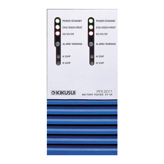
PFX2011
PFX2021
PFX2121
PFX2331
PFX2332
Part No. Z1-002-582, IB003122
Aug. 2004
5V-5A 2-ch Charge/Discharge
Power Supply Unit
20V-10A Charge/Discharge
Power Supply Unit
120-ch
Control Unit
5-Unit
Frame
5-Unit
Large Capacity Frame
Table of
Contents
Previous
Page
Next
Page
1
2
3
4
5
Advertisement
Table of Contents
Need help?
Do you have a question about the PFX2000 Series and is the answer not in the manual?
Ask a question
Questions and answers
Related Manuals for Kikusui PFX2000 Series
Test Equipment Kikusui PFX2500 Series Operation Manual
Charge/discharge system controller (105 pages)
Test Equipment Kikusui PLZ-U Series Operation Manual
Electronic load (190 pages)
Test Equipment Kikusui PCZ1000A Operation Manual
Ac electronic load (100 pages)
Test Equipment Kikusui PLZ-5W Series Setup Manual
Electronic load (9 pages)
Test Equipment Kikusui PLZ-5WH2 Series User Manual
Electronic load (190 pages)
Test Equipment Kikusui PFX2021 Operation Manual
Charge/discharge battery test system (104 pages)
Test Equipment Kikusui PLZ-3WH Series Operation Manual
Electronic load (173 pages)
Test Equipment Kikusui PFX2731S Operation Manual
High rate battery tester (54 pages)
Test Equipment Kikusui PLZ 3W Series Operation Manual
Electronics load (194 pages)
Test Equipment Kikusui TOS5101 Operation Manual
Withstanding voltage tester (139 pages)
Test Equipment Kikusui tos6200 Operation Manual
Earth continuity tester (158 pages)
Test Equipment Kikusui TOS3200 Operation Manual
Leakage current tester (208 pages)
Test Equipment Kikusui TOS6200 Operation Manual
Earth continuity tester (157 pages)
Test Equipment Kikusui TOS6200A User Manual
Earth continuity tester (154 pages)
Test Equipment Kikusui TOS9200 Operation Manual
Tos9200 series withstanding voltage/insulation resistance tester (104 pages)
Test Equipment Kikusui TOS9200 Operation Manual
Tos9200 series withstanding voltage/insulation resistance tester (172 pages)
This manual is also suitable for:
Pfx2011
Pfx2021
Pfx2121
Pfx2331
Pfx2332
Table of Contents
Print
Rename the bookmark
Delete bookmark?
Delete from my manuals?
Login
Sign In
OR
Sign in with Facebook
Sign in with Google
Upload manual
Upload from disk
Upload from URL


Need help?
Do you have a question about the PFX2000 Series and is the answer not in the manual?
Questions and answers