Table of Contents
Advertisement
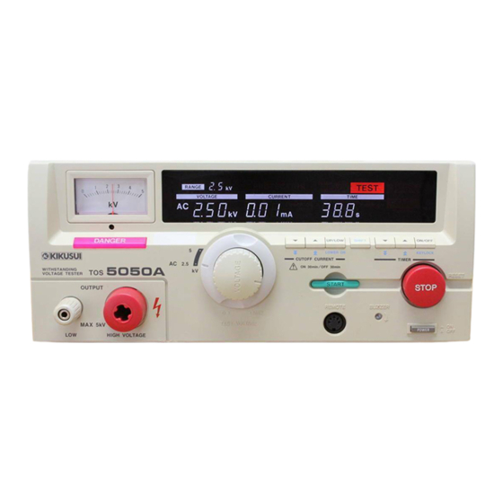
OPERATION MANUAL
WITHSTANDING VOLTAGE TESTER
TOS5000 Series
TOS5050A
TOS5051A
DANGER
This Tester generates high voltage.
• Any incorrect handling may cause death.
• Read "Handling Precautions" in this manual to
prevent accident.
• Keep this manual near the tester for easy access
of the operator.
Part No. Z1-002-972, IB004839
Aug. 2009
Advertisement
Table of Contents


Need help?
Do you have a question about the TOS5050A and is the answer not in the manual?
Questions and answers