
Related Manuals for Kikusui PCZ1000A


Summary of Contents for Kikusui PCZ1000A
- Page 1 Part No. Z1-004-002, IB013706 Jul 2018 General Description Unpacking and Installation Operation OPERATION MANUAL Remote Control AC Electronic Load Maintenance PCZ1000A and Calibration Specifications Appendix...
- Page 2 If you find any incorrectly arranged or missing pages in this manual, they will be replaced. If the manual gets lost or soiled, a new copy can be provided for a fee. In either case, please contact Kikusui distributor/ agent, and provide the “Kikusui Part No.” given on the cover page.
-
Page 3: Power Requirements Of This Product
• Use a fuse element having a shape, rating, and characteristics suitable for this product. The use of a fuse with a different rating or one that short circuits the fuse holder may result in fire, electric shock, or irreparable damage. PCZ1000A... - Page 4 This page is intentionally blank. PCZ1000A...
- Page 5 When this symbol is marked on the product, see the relevant sections in this manual. Protective conductor terminal. Chassis (frame) terminal. On (supply) Off (supply) In position of a bi-stable push control Out position of a bi-stable push control PCZ1000A...
-
Page 6: Safety Precautions
For details, see the relevant page in the operation manual. Cover • Some parts inside the product may cause physical hazards. Do not remove the external cover. PCZ1000A... - Page 7 • To maintain the performance and safe operation of the product, it is recommended that periodic maintenance, inspection, cleaning, and calibration be performed. Service • Kikusui service engineers will perform internal service on the product. If the product needs adjustment or repairs, contact your Kikusui distributor or agent. PCZ1000A...
-
Page 8: How To Read This Manual
How to Read This Manual Introduction Thank you for purchasing the PCZ1000A AC electronic load. This manual is intended for first-time users of the PCZ1000A. It gives an overview of the PCZ1000A and describes various settings, program messages, maintenance, and precautions, etc. -
Page 9: Description
The appendix contains the basic operating modes, operating range, and troubleshooting. Notation used in this manual • The PCZ1000A AC electronic load is simply referred to as the PCZ1000A in this manual. • The term "computer" is used to refer to a personal computer, workstation, or similar. -
Page 10: Table Of Contents
Operation Modes - - - - - - - - - - - - - - - - - - - - - - - - - - - - - - - - - - - - - - - - - 3-10 Operation Mode Display - - - - - - - - - - - - - - - - - - - - - - - - - - - - - - - - - 3-10 viii PCZ1000A... - Page 11 Cleaning the Panel - - - - - - - - - - - - - - - - - - - - - - - - - - - - - - - - - - - - - - 5-2 PCZ1000A...
- Page 12 Troubleshooting - - - - - - - - - - - - - - - - - - - - - - - - - - - - - - - - - - - - - - - - - - - A-7 Index PCZ1000A...
-
Page 13: Function Index
How do I perform maintenance? Cleaning and Inspection What is the procedure for calibration? Calibration of the Ammeter on the Master Unit During Parallel 3-30 Operation How do I reset the PCZ1000A to the factory default Factory Default Settings 3-34 settings? PCZ1000A... -
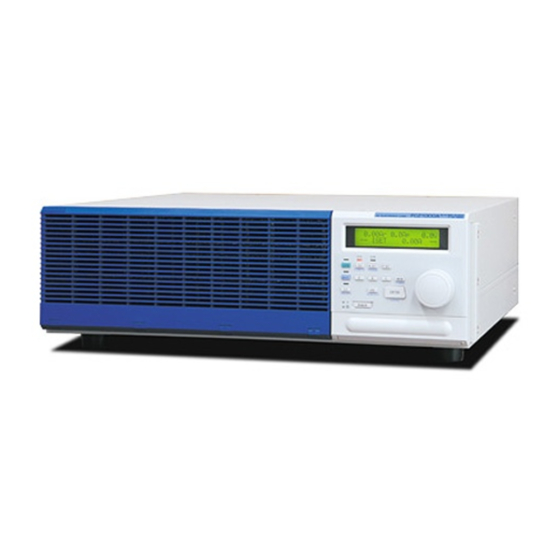
Page 14: Front Panel
Front panel Control panel Display Control panel Display PCZ1000A... - Page 15 Fine and coarse adjustment of setting values ENTER Enter key for preset memory LOCAL Local operation selection key Cancels the selected function. ALM CLR Clears an alarm. Ventilation louvers Provides ventilation for the unit. Fitted with an internal dust filter. xiii PCZ1000A...
-
Page 16: Rear Panel
LOAD INPUT Load input terminals Serial number The serial number of the instrument RS232C RS232C connector used by the remote control function AC INPUT AC power supply inlet FUSE Power supply fuse holder, includes a spare fuse (1) 2-2, PCZ1000A... -
Page 17: Chapter 1 General Description
General Description This chapter gives an overview and describes the features of the PCZ1000A. -
Page 18: About This Manual
Up to five units can be used in parallel under the control of a single master unit. A PCZ1000A can be set as a master and up to four slave PCZ1000As connected in parallel (max. 5 kW, 50 Arms). The total power is displayed on the front panel of the master unit. -
Page 19: Options
Useful for testing single-phase/three-wire or three-phase/three-wire AC power supply loads. Options The following options are available for the PCZ1000A. For details on the options, contact your Kikusui agent or distributor. ■ Rack mounting option Part Name Model No. - Page 20 Signal cable for parallel operation ■ Cable used for parallel operation Part name Model No. Remarks Signal cable for PC01-PCZ1000A 300 mm, 10-pin parallel operation PCZ1000A...
-
Page 21: Chapter 2 Unpacking And Installation
Unpacking and Installation This chapter describes the necessary procedures from unpacking the product to preparation before use. -
Page 22: Unpacking Checks
Unpacking Checks Upon receiving the PCZ1000A, make sure the package contains all the necessary parts and that the PCZ1000A has not been damaged during transportation. If you find any damage or other problems, please contact your Kikusui distributor or agent. - Page 23 Do not place any object on the PCZ1000A. In particular, do not place heavy objects on the product as this could result in a malfunction. Do not place the PCZ1000A on a tilted surface or in a location subject to ● vibrations.
-
Page 24: Precautions For Moving
When moving or transporting the PCZ1000A to an installation site, observe the following precautions. Turn off the POWER switch. ● Moving the PCZ1000A with the power on may result in electrical shock or damage. Remove all wiring. ● Moving the PCZ1000A with cables connected may cause wires to break or injuries due to the product falling over. -
Page 25: Attaching To The Rack Mount Frame
M4 screws (4 locations) Collar (4 locations) Rubber feet (4 locations) Screws for attaching feet (4 locations) Fig.2-2 How to Remove the Rubber Feet How to remove the rubber feet Undo the screws and remove the four rubber feet. PCZ1000A... -
Page 26: Checking The Input Power And Fuse
Checking the Input Power and Fuse The PCZ1000A is used by selecting one of the four input line voltage ranges shown in Fig.2-3. Check that the factory default setting is correct for the AC line input voltage you will be using. Also, ensure that the line fuse is properly rated for the AC line supply. - Page 27 Insert the screwdriver as shown in Fig.2-4. Move the screwdriver in the direction indicated by the arrow to lever the fuse holder out of the PCZ1000A. Confirm that the rating of the installed fuse is appropriate for the line voltage to be used. Also check that the time-current characteristics are appropriate for the application.
-
Page 28: Connecting The Ac Power Cord
Check that the AC power line is compatible with the input power ratings of the PCZ1000A. The PCZ1000A can be used with power supplies with voltages between 100 Vrms and 240 Vrms, and with a frequency of 50 Hz or 60 Hz. -
Page 29: Load Wiring
Precautions Concerning Wiring Electric wire used WARNING • Risk of fire. Ensure that the cables used to connect the PCZ1000A to the equipment under test have sufficient current-carrying capacity compared to the rated input current of the PCZ1000A. • Risk of electric shock. To ensure sufficient insulation compared to the isolation voltage ±500 Vdc, use a reinforced insulation cable... -
Page 30: Overvoltage
In such condition, the input voltage may fall below the minimum operating voltage of the PCZ1000A causing the current waveform to be distorted. In some cases, the input voltage may exceed the maximum input voltage and cause damage to the PCZ1000A. -
Page 31: Input Voltage Waveforms
Input Voltage Waveforms The PCZ1000A controls the amplitude of the sinusoidal current by detecting the RMS value of the input voltage waveform. In the following cases, distortion may appear on the current waveform and the load current operation may become unstable. - Page 32 Distortion may also appear on the current waveform and the load current operation may become unstable if a voltage with a DC offset is input as in Fig.2-9. Please do not input voltage waveforms with a DC offset to the PCZ1000A. Voltage waveform...
-
Page 33: Connection To The Load Input Terminals
■ This cover is fitted using the hole on the right side of the terminal cover when the PCZ1000A is shipped from the factory to prevent the load input terminals from being exposed. Please attach the cover as shown in Fig.2-10 when not using the load input terminal block. - Page 34 Terminal screw Crimped terminal L N G Attachment hole on left Fig.2-11 Connecting the Load Input Wiring 2-14 PCZ1000A...
-
Page 35: Chapter 3 Operation
Operation This chapter describes each mode and function of the operation. -
Page 36: Basic Panel Operation
Basic Panel Operation The main operations of the PCZ1000A can be selected simply by pressing the function keys shown in Fig.3-1. Pressing the ESC key clears the currently selected function. Functions key Preset memory key Rotary knob ESC (ALM CLR) key ENTER (LOCAL) key Fig.3-1... -
Page 37: Preset Memory Key
To reset each setting to its default value, turn on the POWER switch with the MEM page 3-34 key held down. A, B or C Calls up and displays a setting stored in memory A, B or C. In the memory save mode, these keys select memory A, B or C. PCZ1000A... -
Page 38: Other Keys
During remote control operation, "REM" is displayed at the bottom right of the front panel display as shown in Fig.3-2. 0.00Ar 0.0Ap 0.0V Fig.3-2 Remote Control Display Invalid operations A warning "pip" tone sounds if you try to select any invalid settings or press any inappropriate keys during operation. PCZ1000A... -
Page 39: Turning On The Power
This section describes the procedure for turning on the power. No load current will page 3-6 flow if the PCZ1000A is turned on with its factory default settings. To allow a load current to flow, the PCZ1000A needs to be set to load-on mode. -
Page 40: Load-On/Load-Off
The load on/off state is not stored. The PCZ1000A always starts up with the load turned off when the power is turned on. If the PCZ1000A is not turned on with the condition of the last setting when the page 5-2 POWER switch was turned off, the life of back-up battery may be dead. -
Page 41: Protection Functions And Alarms
Protection Functions and Alarms If an abnormal input is detected by the internal circuit of the PCZ1000A, the PCZ1000A automatically goes to load-off to protect the equipment under test, an alarm message appears on the lower part of the front panel display, and a buzzer sounds. - Page 42 The POCP function is activated if the current reaches 48 Apeak or greater. In this case, the buzzer sounds and the PCZ1000A automatically goes to the load-off state. The following message appears in the lower part of the front panel display.
- Page 43 PCZ1000A other than the one where the alarm was triggered. *ALARM* EXT1 • If the POWER switch is turned off on any PCZ1000A that is not in an alarm state, regardless of whether it is the master or slave, an external alarm 1 occurs on the other PCZ1000As.
-
Page 44: Operation Modes
14 Vrms or more. In the range in which the input voltage is 10 V rms or less, the PCZ1000A is unable to sink its maximum current (10 Arms; see "Operation range of the PCZ1000A" above). Thus, even when a current of the ISET value or less flows, the PCZ1000A apparently operates in the CC operation range, causing both the C.C and C.R LEDs to blink. -
Page 45: Cc Mode Operation
Turn the rotary knob slowly clockwise to set the exact current limit value. 0.00Ar 0.0Ap 100.1V -- ISET 5.00A Press the LOAD key to change to the load-on state. The LED above the LOAD key illuminates and current flow starts. 5.00Ar 7.1Ap 100.0V -- ISET 5.00A 3-11 PCZ1000A... -
Page 46: Constant Resistance (Cr) Mode
5.00A • An offset current of several tens of mA may flow if the current limit value is set to approximately 0 A. (The setting accuracy of the PCZ1000A is ± (1 % + 0.1 A).) • The current limit value and the resolution at close to 0 A may be degraded due to this offset current. - Page 47 (9.000 0 Ω to 1 000.0 Ω), the resistance limit value remains unchanged when the range is switched. However, because the setting resolution is different in the two ranges, the setting changes to the next highest resistance value for the new range. 9.43Ar 13.3Ap 84.9V -- RSET 9.0000 3-13 PCZ1000A...
- Page 48 • If the resistance limit setting is such that the current is close to 0 A (for example, if the resistance limit is set to 10 kΩ for a 10 V input), an offset current of several tens of mA may flow. (The setting accuracy of the PCZ1000A is ± (2 % + 0.2 A).) •...
-
Page 49: Constant Power (Cp) Mode
Use the rotary knob to set the power limit value. 0.00Ar 0.0Ap 179.6V -- PSET 800W Press the LOAD key to change to the load-on state. The LED above the LOAD key illuminates and current flow starts. 4.46Ar 6.3Ap 179.4V -- PSET 800W 3-15 PCZ1000A... -
Page 50: Crest Factor Function
"CREST FACTOR" appears in the lower part of the display. 0.00Ar 0.0Ap 95.1V --CREST FACTOR 1.4-- Use the rotary knob to set the crest factor. (The crest factor is set to 2.0 in this example.) 0.00Ar 0.0Ap 95.1V --CREST FACTOR 2.0-- 3-16 PCZ1000A... -
Page 51: Saving And Recalling Preset Memory
Crest factors cannot be modified using the DMEM key. CC mode Current limit, CF function (crest factor setting) CR mode Resistance limit, range setting CP mode Power limit 3-17 PCZ1000A... -
Page 52: Saving Preset Memory
• To save the crest factor value in CC mode to memory, first set the crest factor value and then press the I SET key to change to CC mode, then press the MEM key followed by the A, B, or C key to save the value of current limit and crest factor together. 3-18 PCZ1000A... -
Page 53: Changing Preset Memory
Use the rotary knob to change the limit value. The limit value changes to the new setting immediately. 7.13Ar10.1Ap 84.9V --Rval<C>9.0909 Press the SHIFT + MEM (DMEM) key or ESC key to end the operation. The display returns to its state prior to the change. 3-19 PCZ1000A... -
Page 54: Recalling Preset Memory
Recalling Preset Memory Memory settings for the currently set mode can be recalled regardless of whether the PCZ1000A is in the load-on or load-off state. The following example describes how to recall preset memory in CR mode. Press the R SET key to enable CR mode. -
Page 55: Parallel Operation And Tracking Operation
PCZ1000As with less than version 1.40. 3.7.1 Configuration (CONFIG) Settings The operation of the PCZ1000A can be set to standalone operation, parallel operation, tracking operation, or total current calibration by the configuration setting. Pressing the SHIFT + I SET (CONFIG) key brings up the configuration screen. -
Page 56: How To Display And Set Configuration Settings
Use the rotary knob to select the setting value. Press the ENTER key to move to the next setting. Repeat Step 2 and Step 3 to specify the other settings. Use the SHIFT + I SET (CONFIG) key or ESC key to exit configuration setting. 3-22 PCZ1000A... -
Page 57: Parallel Operation
Maximum Current No. of Slave Units Maximum Power (RMS) (Peak) 20 A 80 A 2 000 W 30 A 120 A 3 000 W 40 A 160 A 4 000 W 50 A 200 A 5 000 W 3-23 PCZ1000A... -
Page 58: Procedure For Connecting Units In Parallel
• Ensure that the insulation on the load cable you use has good fire resistance. • Ensure that the cables to the load input terminals on each PCZ1000A are as similar in length as possible. Turn off the POWER switch. -
Page 59: Procedure For Setting Master And Slave Units
ESC key to exit CONFIG setting. On the master unit, proceed to the next step. On the slave units, "P <<Slave>>" appears on the front panel display. << Slave >> Press the ENTER key to select ">3:Parallel Ope.". 3-25 PCZ1000A... - Page 60 When you carry out parallel operation by a mode except CP mode, be sure to change PSET value of the master unit to the required power value. 3-26 PCZ1000A...
-
Page 61: Tracking Operation
Slave Three-phase/three-wire connection example Single-phase/three-wire power supply PARALLEL Master Flat cable PARALLEL Unit under test The reverse connection of the polarity (L and N) is also allowed. Slave Single-phase/three-wire connection example Fig.3-10 Tracking Operation Connection 3-27 PCZ1000A... -
Page 62: Connecting Units For Tracking Operation
• Ensure that the insulation on the load cable you use has good fire resistance. • Ensure that the cables to the load input terminals on each of the PCZ1000A are as similar in length as possible. - Page 63 When tracking operation is set, "T" appears on the bottom left of the front panel display. 0.00Ar 0.0Ap 100.1V ISET 5.00A On the slave units, "T << Slave >>" appears on the front panel display. 0.00Ar 0.0Ap 100.1V << Slave >> 3-29 PCZ1000A...
-
Page 64: Calibration Of The Ammeter On The Master Unit During Parallel Operation
Calibration of the Ammeter on the Master Unit During Parallel Operation The ammeter of the PCZ1000A when used for parallel operation is calibrated at the shipment from the factory. However, the ammeter accuracy can be improved further by calibrating the instrument under the actual parallel operation conditions Preparation for Calibration •... -
Page 65: Calibration Procedure
> 3: Parallel Ope. Press the ENTER key to display ">4: Calibration". This changes the PCZ1000A to calibration mode. Proceed to the calibration procedure. ■ Calibrating the offset and gain for the total current (RMS) Press the I SET key to display "IRS OFFS XXXXX". - Page 66 If you want to stop calibration before finishing, press the MEM key to display "SAVE?" and then press the ESC key. Press the ENTER key. The calibration data is written to internal memory in the PCZ1000A. This completes calibration. 3-32...
-
Page 67: Alarms During Parallel And Tracking Operation
Pressing the SHIFT + ESC (ALM CLR) key on the master unit clears the alarm on the PCZ1000A other than the one that generated the original alarm. To clear the alarm on the PCZ1000A where it was generated, press SHIFT + ESC (ALM CLR) on that unit. -
Page 68: Factory Default Settings
Hold down the MEM key as you turn on the POWER switch and do not release until after about 8 seconds. First, the model name and firmware version are displayed, then the screen shown in Fig.3-12 appears for approximately 2 seconds and the instrument is set back to its factory default settings. PCZ1000A **** RESET **** Fig.3-12 Completion Screen When Restoring Factory Default Settings... -
Page 69: Chapter 4 Remote Control
Remote Control Remote Control This chapter describes how to program the remote control features of the PCZ1000A using an external device such as a personal computer. The explanation covers the command syntax, details of each command, and the registers. -
Page 70: Overview Of Remote Control
Overview of Remote Control As an alternative to using the front panel, the PCZ1000A can also be operated remotely via an RS-232C interface. 4.1.1 RS232C Interface RS232C connection The RS232C port on the PCZ1000A is a standard D-sub 9-pin male connector. - Page 71 DC Codes Code Function ASCII Code Request to send Transmission stop request Transmission control from the PC to the PCZ1000A. Pause Resume transmission Within 10 characters The RS232C terminal must pause transmission within 10 characters after receiving DC3. Transmission control from the PCZ1000A to the PC.
-
Page 72: Programming Format
Programming Format This section describes the general programming format. Program message terminator The PCZ1000A can receive any of the three types of program message terminators specified below. • CR • LF • CR + LF 4.2.1 Program Messages The program messages sent from the RS-232C terminal to the PCZ1000A are as... -
Page 73: Device Messages
Figures to the right of the least significant digit are rounded down. • The PCZ1000A does not support the use of exponents. • Note that the PCZ1000A discards figures to the right of the least significant digit, rather than rounding them off. -
Page 74: Configuration Of Device Messages
Number program data CCRP <SP> CRRANGE Number program data <SP> ISET Decimal program data <SP> RSET Decimal program data <SP> PSET Decimal program data <SP> Number program data Character program data <SP> Decimal program data CFSET CURR CURP VOLT SYSCON ALMCLR PCZ1000A... - Page 75 1.800 0 Ω to 5 000.0 Ω 3 333.3 Ω 2 500.0 Ω 2 000.0 Ω 90 W to 2 100 W 135 W to 180 W to 225 W to PSET 3 150 W 4 200 W 5 250 W PCZ1000A...
-
Page 76: System Messages
Cancels local lockout LLO? Returns "0, 1" Resets to the factory default settings (See "Factory Default Settings" on page 3-34. Note, however, that the configuration settings remain unchanged.) • The instrument has no messages for controlling the preset memory function. PCZ1000A... -
Page 77: Assignment Of Register Bits
"FAU?" request. To determine the present status, send "FAU?" to clear the register and then send "FAU?" again to retrieve the present status. Fault Register 2 Decimal Status of Fault Register 2 Value External alarm 1 triggered (EXT1 ALARM) PCZ1000A... -
Page 78: Error Register
Error in data other than program header DATA ERROR Error due to data out of range RANGE ERROR Received message is not currently enabled INVALID MESSAGE Buffer full: CR or CF was not received within 35 BUFFER FULL characters 4-10 PCZ1000A... -
Page 79: Chapter 5 Maintenance And Calibration
Maintenance and Calibration This chapter describes the maintenance procedures including cleaning, inspection, and calibration. -
Page 80: Cleaning And Inspection
Replacing the Backup Battery The PCZ1000A has an internal battery used to backup the panel settings when the power is turned off. If the panel settings when the instrument is turned on are not the same as when it was last turned off, the battery may be dead. -
Page 81: Calibration
• Clogged filters hinder cooling inside the PCZ1000A which can cause malfunctions and shorten the service life. • When the PCZ1000A is in operation, air is sucked through the dust filter to cool the inside. If moisture is present in the dust filter, the temperature or humidity inside the PCZ1000A increases and may cause a malfunction. - Page 82 This page is intentionally blank. PCZ1000A...
-
Page 83: Specifications
Specifications This chapter gives the specifications and dimensions of the PCZ1000A. - Page 84 Resolution Ammeter (RMS display mode) Number of display digits (full scale) 10.00 Arms Within ± 1 % of FS Accuracy Ammeter (peak display mode) Number of display digits (full scale) 40.0 Apeak Within ± 2 % of FS Accuracy PCZ1000A...
- Page 85 External alarm 1 (EXT1) Another unit has detected an alarm during parallel or tracking operation. External alarm 2 (EXT2) Alarm detected when the PC01-PCZ1000A flat cable comes unplugged during parallel or tracking operation (only on slave units that become disconnected from the master).
- Page 86 Connector D-SUB 9-pin connector (male) Baud rate 9 600 bps (fixed) No. of data bits 8 bits (fixed) No. of stop bits 2 bits (fixed) Parity bit None (fixed) Flow control XON/XOFF Use a cross cable (null modem cable). PCZ1000A...
-
Page 87: Dimensions
4-M screw holes (max. depth 6 mm (0.24 inch)) MAX465 (18.31) MAX20 (0.79) MAX455 (17.91) 400 (15.75) 26 (1.02) 430 (16.93) 4-M screw holes including opposing surfaces (max. depth 16 mm (0.63 inch)) Unit: mm (inch) Fig.6-1 PCZ1000A outline drawing PCZ1000A... - Page 88 This page is intentionally blank. PCZ1000A...
-
Page 89: Appendix
Appendix The appendix contains the basic operating modes, operating range, and troubleshooting. -
Page 90: Explanation Of Operating Functions
A.1.1 Operating Functions Operating Range The operating range of the PCZ1000A is limited by the rated current, rated voltage, and rated power. The PCZ1000A can only be operated within the range indicated by the shaded area in the figure below. - Page 91 Operation of PCZ1000A Operation of a true constant current Fig.A-2 Differences in Operation Crest factor function The PCZ1000A varies the crest Voltage waveform factor (CF = peak/rms; see the definition below) by changing the Current waveform angular width (using the 90° and...
-
Page 92: Explanation Of Operating Mode
CP mode. As the RMS value of the input voltage (V1) increases, the operating point of the PCZ1000A moves upwards from point A in CC mode. Operation changes to CP mode when the operating point reaches point B. -
Page 93: Constant-Resistance (Cr) Mode
As the RMS value of the input voltage (V1) increases, the operating point of the PCZ1000A in CR mode starts from point F, then changes to operation in CC mode on reaching point G. As the voltage increases further to reach point H, the PCZ1000A operation changes again to CP mode (see the above explanation of CR mode operation). -
Page 94: Constant-Power (Cp) Mode
In constant-power (CP) mode, the current flow is controlled to maintain constant power dissipation in the load. The PCZ1000A operates as a constant-power load, as shown in Fig.A-8 load within the range shown in Fig.A-1. If the RMS input voltage increases, the PCZ1000A reduces the RMS current flow accordingly to keep the apparent power (P= V x I) constant. -
Page 95: Troubleshooting
If none of the items apply to your case, we recommend that you initialize the page 3-34 PCZ1000A to the factory default settings (this clears the memory contents). If this does not correct the problem, contact your Kikusui agent or distributor. - Page 96 PCZ1000A ERR" displayed on the repaired. panel? ("x" may varies Abnormal condition has been occurred in the internal circuit. depends on the contents of Immediately stop using the PCZ1000A and arrange for it to be the error) repaired. PCZ1000A...
- Page 97 ........2-3 calibration........3-21 3-30 Options ............1-3 communication settings ........4-8 overcurrent protection........3-7 constant-current load ........A-2 overpower protection ........3-8 constant-current mode ....3-11 overvoltage ............2-10 constant-power mode ......3-15 protection...........3-8 constant-resistance mode..... 3-12 crest factor function......3-3 3-16 PCZ1000A...
- Page 98 RANGE switch ..........3-5 resistance limit value........3-3 signal cable for parallel operation ....1-4 storage humidity range .......... 2-3 temperature range ........2-3 use in a flammable atmosphere ...... 2-2 voltage range selection switch for the line input ........ 2-6 PCZ1000A...
- Page 100 In either case, please contact your Kikusui agent or distributor. At that time, inform your agent or distributor of the “Part No.” written on the front cover of this manual.
Need help?
Do you have a question about the PCZ1000A and is the answer not in the manual?
Questions and answers