Table of Contents
Advertisement
Quick Links
User's Manual
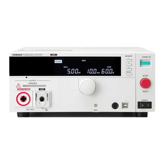
Withstanding Voltage Tester
TOS5200
DANGER
This product generates high voltage!
Improper operation can lead to serious accidents.
To prevent accidents, be sure to read the section
"Safety Precautions during Testing" in this manual.
Keep this manual close to the product so that the
operators can read the manual at any time.
PART NO. IB027962
Sep. 2014
General Description
Installation and
Preparation
Safety Precautions
during Testing
Panel Operation Basics
Withstanding Voltage Test
External Control
Maintenance
Specifications
1
2
3
4
5
6
7
8
App
Advertisement
Table of Contents

Related Manuals for Kikusui TOS5200


Summary of Contents for Kikusui TOS5200
- Page 1 Preparation Safety Precautions during Testing User’s Manual Panel Operation Basics Withstanding Voltage Tester Withstanding Voltage Test TOS5200 External Control Maintenance Specifications DANGER This product generates high voltage! Improper operation can lead to serious accidents. To prevent accidents, be sure to read the section “Safety Precautions during Testing”...
-
Page 2: About The Manuals
In either case, please contact Japanese (1 sheet): [Z1-006-150] your Kikusui agent or distributor. At that time, inform your English (1 sheet): [Z1-006-152] agent or distributor of the “Part No.” written on the front cover CD-ROM (1 pc.) -
Page 3: Notes To The Supervisor
• You operate the tester without grounding it. • You operate the tester without using rubber gloves for electrical work. • You come close to a location that is electrically connected to an output terminal while output is being generated. TOS5200... -
Page 4: Safety Precautions
Notations Used in This Manual Safety Precautions When using this product, be sure to observe the “Safety • The TOS5200 Withstanding Voltage Tester is also referred Precautions” in the Safety information manual. to as the TOS5200. • Device under test is also referred to as DUT. -
Page 5: Table Of Contents
To Use the Product for a Long Time Free of Malfunctions ..............30 Panel Operation Basics Parts of the Screen..............................32 Panel Operations................................34 Switching screens ....................34 Selecting items ............................35 Entering values....................35 Locking panel operations (key lock) ..............36 Talk mode......................36 TOS5200... - Page 6 Inspection of test leads and the judgment feature ..........62 Calibration ......................62 Specifications Withstanding voltage tester................. 64 Other features............................66 Interfaces..............................67 General................................ 69 Outline drawing ....................70 Appendix A List of Default Settings ............72 Initializing the TOS5200 ..................72 Protection Functions ...............74 TOS5200...
- Page 7 Test Start Operation and Display..........75 D Troubleshooting ............... 76 Index ............79 TOS5200...
-
Page 8: Search By Topic
• How do I use each of the two test leads? p.40 ➔ “Using test leads” p.24 • How does the TOS5200 display the judgment results? • I want to check that measurements are ➔ “When a test finishes” being performed correctly before I start p.51... - Page 9 ➔ “Using the Protection Cover” p.21 ➔ “Locking panel operations (key lock)” p.36 • How do I control the TOS5200 using external signal input? ➔ “SIGNAL I/O Connector” p.54 • How do I release the interlock feature? ➔ “Turning the Power On”...
-
Page 10: Front Panel
Function DANGER LED Lights in red when a test is being performed. p.48 READY: Lights in white when the TOS5200 is ready to perform a test. p.48 TEST: Lights in red when a test is being performed. p.48 Status indicators PASS: Lights in green when a test passes. - Page 11 POWER switch p.22 Turns the power on [ ] and off [ Protection cover Cover designed to prevent incorrect operation of the TOS5200. p.21 This indicates an operation that requires you to press a key while holding down SHIFT. TOS5200...
-
Page 12: Rear Panel
Serial number The product’s serial number — Communication RS232C port RS232C interface connector interface manual SIGNAL I/O connector External control signal connector p.54 A multipurpose ground terminal provided for the stable operation of the TOS5200. Use it if necessary. TOS5200... -
Page 13: General Description
General Description This chapter gives an overview of the TOS5200 and explains the options that are available for it. -
Page 14: Product Overview
● Newly developed constant-voltage output for stable testing The TOS5200 is not affected by AC line interference. Because the output voltage is main- tained at a fixed value even if the AC line voltage or frequency changes, stable tests can be performed even in locations where the power supply is unstable. - Page 15 ● Protection against incorrect operations In addition to the key lock feature, the TOS5200 has a protection cover for the part of its panel that is used to change test conditions. This cover is useful in preventing incorrect operations when you want to perform tests with fixed conditions.
-
Page 16: Options
Options The following options are available for the TOS5200. For information about options, contact your Kikusui agent or distributor. Rack mount option Name Model Note KRA4-TOS For EIA inch racks Rack mount adapter KRA200-TOS For JIS millimeter racks KRA4-TOS Model RC01-TOS/RC02-TOS remote control box The remote control box can be used to start and stop withstanding voltage test. - Page 17 Rated voltage 4 kV 5 kV Model PL02-TOS warning light unit The warning light unit indicates that the TOS5200 is performing a test. This enables you to see that a test is in progress from a dis- tance. TOS5200...
- Page 18 This page is intentionally blank. TOS5200...
-
Page 19: Installation And Preparation
Installation and Preparation This chapter describes how to prepare this product for use. -
Page 20: Connecting The Power Cord
If the supplied power cord cannot be used because the rated voltage or the plug shape is incompatible, have a qualified engineer replace it with an appropriate power cord that is 3 m or less in length. If obtaining a power cord is difficult, contact your Kikusui agent or dis- tributor. -
Page 21: Using The Protection Cover
Even when the cover is attached, you can still recall settings from memory, start and stop tests, perform remote operations, and control the TOS5200 through its USB port. If the tester will be used to repeatedly perform tests with fixed conditions, such as when being used as part of a manufacturing line, attach the protection cover to ensure safe operation of the tester. -
Page 22: Turning The Power On
When the TOS5200 is turned on, a self-test is run, and all the indicators on the front panel light. To ensure safety, check that all the indicators light before you use the TOS5200. It is especially dangerous to use the tester if its DANGER LED is broken. -
Page 23: Turning The Power Switch On
Connect the included SIGNAL I/O plug to the SIGNAL I/O connector. Connecting the SIGNAL I/O plug will release the interlock feature. Press the ( ) side of the POWER switch to turn the TOS5200 on. Check the firmware version (Ver x.xx) that is displayed on the screen. -
Page 24: Connecting To The Device Under Test (Dut)
This is dangerous, so be sure to connect the DUT correctly. • Be sure to connect the low-voltage test lead (black) first. Check that the POWER switch is off and that the DANGER LED is off. TOS5200 POWER OUTPUT DANGER Check that there are no tears or breaks in the test lead insulation. - Page 25 AGE terminal. Low-voltage test lead (black) High-voltage test lead (red) Check that the DANGER LED is turned off. TOS5200 OUTPUT DANGER Reducing the effect of noise Noise may be generated if the outputs are shorted or if the DUT insulation is damaged. Elec- tronic devices in the surrounding area may malfunction due to the effect of this noise.
-
Page 26: Using The Optional High Voltage Test Probe (Model Hp01A-Tos/Hp02A-Tos)
Disconnect the high-voltage test lead (red) from the front-panel HIGH VOLTAGE terminal. Disconnect the high-voltage test lead (red) from the DUT. Disconnect the low-voltage test lead (black). You can disconnect the low-voltage test lead (black) first from either the DUT or the TOS5200. TOS5200... -
Page 27: Safety Precautions For Testing
Safety Precautions for Testing This chapter describes the precautions that must be followed to perform tests safely. -
Page 28: Pre-Test Inspection
● During testing, do not turn the POWER switch off except in an emergency. Testing Precautions During testing, the TEST and DANGER LEDs light. When these LEDs are lit, the TOS5200 is generating a high voltage. During testing, be sure to wear rubber gloves for electrical work. If obtaining these gloves is difficult, contact your Kikusui agent or distributor. -
Page 29: Remote Control Precautions
Remote Control Precautions When you are controlling the TOS5200 remotely, external signals are used to turn the high voltage on and off. To prevent accidents, follow the safety measures given below. ● Make sure that high voltages are not generated unintentionally. -
Page 30: Forbidden Actions
• For repairs, contact your Kikusui agent or distributor. If the TOS5200 is in one of the states explained below, it may be malfunctioning in a very dangerous manner—it may not be possible to turn off the high voltage that is being gener- ated. -
Page 31: Panel Operation Basics
Panel Operation Basics This chapter describes how to select items on the screen and how to enter values. -
Page 32: Parts Of The Screen
50Hz 60Hz LOWER W COMP RISE TEST PASS Data input FAIL area To reset the TOS5200 to the factory default settings, hold down SHIFT, and turn the POWER p. 72 switch on. Status indicators These display the status. Display Description... - Page 33 Parts of the Screen Icon area The TOS5200 status is displayed using icons or characters. Display/icon Status Model RC01-TOS/RC02-TOS remote control box connected p. 16 Keys locked p. 36 Recalled memory number or CONFIG setup screen number p. 37 1 2 3...
-
Page 34: Panel Operations
Panel Operations Switching screens On the TOS5200, you need to change the setup screen depending on the item you want to Memo set. The screen that first From the basic setup screen, you can switch to the additional test conditions setup screen or appears when the CONFIG setup screen. -
Page 35: Selecting Items
50Hz 60Hz LOWER W COMP RISE TEST PASS FAIL If you hold down SHIFT and turn the rotary knob, you can change the setting resolution. While you hold down SHIFT, the values change quickly. Rotary knob FUNCTION LOCAL SHIFT TOS5200... -
Page 36: Locking Panel Operations (Key Lock)
PC. It can reduce processing on the PC. If you turn talk mode on, you cannot control the product from a PC. To control the product from a PC, turn talk mode off. For details on talk mode, see the communication interface manual. TOS5200... -
Page 37: Panel Memory
TEST LIMIT UPPER Example of saving to memory 50Hz 60Hz LOWER W COMP RISE TEST PASS number 1 FAIL After the test conditions have been saved, the basic setup screen is displayed in READY mode (the READY LED lights). TOS5200... -
Page 38: Recalling Test Conditions
Press RECALL to recall the test conditions that are saved in the speci- fied memory number. The basic setup screen is displayed, and the icon corresponding to the memory num- ber is displayed in the icon area. The TOS5200 is now set to the recalled test condi- tions. CONFIG... -
Page 39: Withstanding Voltage Test
Withstanding Voltage Test This chapter explains withstanding voltage test, from how to set the test conditions to how to save test results. -
Page 40: About Judgment
About Judgment The TOS5200 judges whether a test results in PASS, L-FAIL, or U-FAIL on the basis of the limits that are set in advance. Judgment result Description Display Buzzer PASS When the test time elapses (TIMER is 0 sec-... -
Page 41: Setting Test Conditions
(Measurement) For details on how to select settings and enter values, see “Panel Operation Basics”. p. 31 For details on how to connect the TOS5200 to the DUT, see “Connecting to the Device under p. 24 Test (DUT)”. For details on the LOWER and UPPER settings, see also “About Judgment”. -
Page 42: Test Conditions (Additional Items)
Test time 0.1 s to 999 s Voltage rise time (RISE) Separate from the test time, you can set the time that the TOS5200 takes to raise the voltage to the test voltage. Voltage rise time 0.1 s to 10.0 s Test conditions (additional items) Press MORE to display the items that are not displayed. - Page 43 0.1 s Voltage rise time Voltage fall time (Fall Time) Separate from the test time, you can set the time that the TOS5200 takes to lower the voltage after a withstanding voltage test ends. This setting is used only when a PASS judgment occurs.
-
Page 44: Config Settings
[0: 50 ms, 1: 100 ms, 2: 200 ms, 3: 1 s, 4: 2 s, 5: 5 s, 6: HOLD] Fail mode function setting [0: off, 1: on] Momentary function setting [0: off, 1: on] Double action feature setting [0: off, 1: on] TOS5200... - Page 45 The fail mode feature is turned on. Judgment result hold time (Pass Hold) This feature enables you to set the length of time that the TOS5200 maintains a PASS judg- ment state. If you set Pass Hold to HOLD, the measured results remain displayed on the screen until you press STOP.
-
Page 46: Config 2 Settings
(0) The 24 Vdc output is turned off while there is a residual voltage and during testing (factory default setting). on (1) The 24 Vdc output is turned on while there is a residual voltage and during testing. TOS5200... - Page 47 The 24 Vdc output is turned on while the READY LED is lit. Protection Sets whether the 24 Vdc output is generated while the TOS5200 is in protection mode. off (0) The 24 Vdc output is turned off when the TOS5200 is in protection mode (factory default setting).
-
Page 48: Starting A Test
Risk of electric shock. During testing, do not touch the test leads and the DUT. WARNING To start a test Check that the TOS5200 is correctly connected to the DUT. When the READY LED lights in white, press START. CONFIG... -
Page 49: To Change The Voltage Setting During A Test
The changed voltage is immediately applied to the test, but the voltage value on the display shows the measured value. After the test finishes, when the TOS5200 returns to the READY state, the new voltage value is shown on the display. - Page 50 TOS5200 to the READY state. ● “PROTECTION” is lit. If PROTECTION is lit, the TOS5200 has switched to protection mode and will not allow p. 74 you to start testing. Resolve the issues causing the PROTECTION mode to be on.
-
Page 51: Finishing A Test
LOWER W COMP RISE TEST PASS FAIL For details on how measured values are judged, see “About Judgment”. p. 40 The operations that the TOS5200 performs after testing finishes for each judgment condition are shown below. Operation PASS U-FAIL L-FAIL Display PASS LED lights in green. -
Page 52: To Clear Judgment Results
Finishing a Test To clear judgment results Press STOP to switch the TOS5200 to the READY state (the READY LED lights). TOS5200... -
Page 53: External Control
External Control This chapter explains how to use the SIG- NAL I/O connector to externally start tests and recall panel memory entries and sequence programs. -
Page 54: Signal I/O Connector
• Keep the signal wire at least 500 mm away from the high-voltage test lead and the DUT. • Do not short the output voltage circuit. • If you use the TOS5200 with incomplete connections, burn outs caused by heating may occur when the output is turned on. - Page 55 Signal name TOS5200 INTERLOCK+ If you open the positive and negative terminals, the output is turned off, and the TOS5200 is switched to Protection mode. Open: The resistance between the two terminals is 1.2 kΩ or greater. Short: The resistance between the two terminals is 1 kΩ or less.
-
Page 56: Internal Construction
Driving a relay Use the output signal to drive a relay. Relay To improve the safety of the circuit, we recom- mend that you insert a protection fuse or connect 400 mA or less a diode. 30 V or less TOS5200... -
Page 57: Starting A Test
5 ms or An interval of 1 ms or more more is required before the next 1 ms STB (IN) 1 ms input signal is received. 10 ms or more more Apply the START signal for more at least 50 ms. TOS5200... -
Page 58: Interlock Feature
By using the interlock feature, you can control the TOS5200 output from an external source. This ensures safe operation of the tester. The first time that you turn the POWER switch on after you purchase the TOS5200, the tester p. 22 will be in PROTECTION mode through the interlock feature. -
Page 59: How To Use The Interlock Feature
When SIGNAL I/O connector pins 1 and 13 are opened, the interlock feature is enabled. When the pins are shorted, the interlock feature is released. When the interlock feature is active, the TOS5200 is in PROTECTION mode. To release the interlock feature, connect the included SIGNAL I/O plug to the rear-panel SIGNAL I/O con- nector. - Page 60 This page is intentionally blank. TOS5200...
-
Page 61: Maintenance
Maintenance This chapter explains daily inspections such as measurement checks. -
Page 62: Pre-Test Inspection
During this inspection, the two test leads are shorted, so you can check for breaks in the test leads at the same time. We recommend that you perform this pre-test inspection before you use the TOS5200. The test leads are consumable parts. Check them periodically for tears and breaks. -
Page 63: Specifications
Specifications This chapter contains the specifications and gives the dimensions of the TOS5200. -
Page 64: Withstanding Voltage Tester
• Values indicated by “TYP” are typical values. They are not guaranteed performance val- ues. • Values indicated by “rdng” are readout values. • Values indicated by “set” are settings. Withstanding voltage tester TOS5200 AC output Output range 0.05 kV to 5.00 kV section Setting ±... - Page 65 Taking size, weight, and cost into consideration, the heat dissipation capability of the voltage generator that is used for withstanding voltage tests has been designed to be one half that of the rated output. Use the TOS5200 within the following limits. If you use the product in a manner that exceeds these limits, the output section may overheat, and the internal protection circuits may be activat- ed.
-
Page 66: Other Features
The test ends when the specified time elapses. Output voltage monitor feature If output voltage exceeds “setting + 350 V” or is lower than “setting - 350 V,” the TOS5200 (Volt Error) switches to PROTECTION mode, output is turned off, and testing finishes. -
Page 67: Interfaces
1 INTERLOCK+ If you open the positive and negative terminals, the output is turned off, and the TOS5200 is switched to Protection mode. Open: If the resistance between the terminals is 1.2 kΩ or greater. Short: If the resistance between the terminals is 1 kΩ or less. - Page 68 Talk mode can be set when RS232C is in use. Talk mode Description Responds only to commands from a PC (factory default setting). Automatically responds at the start and end of a test. The TOS5200 status, settings, and measured values are returned. Response at the <START>...
-
Page 69: General
Applicable under the following conditions The maximum length of all cabling and wiring connected to the TOS5200 is less than 2.5 m. Shielded cables are being used when using the SIGNAL I/O. The high-voltage test lead TL31-TOS is being used. -
Page 70: Outline Drawing
Specifications Outline drawing 250 (9.84) 265 (10.43) MAX330 (12.99) 320 (12.60) Unit: mm (inch) TOS5200... -
Page 71: Appendix
Appendix A List of Default Settings B Protection Functions C Protection Functions D Troubleshooting... -
Page 72: A List Of Default Settings
CONFIG MORE CAL RMT READY PROTECTION switch on. TEST LIMIT UPPER When you initialize the TOS5200, all settings 50Hz 60Hz LOWER W COMP RISE TEST PASS (such as test conditions) and saved data are FAIL reset to the default values shown below. - Page 73 There are three panel memory entries. Initially, these entries all contain AC withstanding volt- age test conditions that comply with safety standards. If you initialize the TOS5200, the panel memory entries are also returned to their default val- ues. Memory number...
-
Page 74: Protection Functions
Protection Functions If one or more of the causes of the following problems occur, the protective circuits will acti- vate, and you will no longer be able to use the TOS5200. This is referred to as PROTECTION mode. When the TOS5200 switches to PROTECTION mode, “PROTECTION” on the screen lights. - Page 75 NAL I/O connec- connector tor (the RR ENABLE signal is at low level) — — — Panel REMOTE connec- — — SIGNAL I/O con- — — nector USB connector or — — RS232C connector SIGNAL I/O con- — nector TOS5200...
- Page 76 This section introduces troubleshooting measures. Typical symptoms are listed. Check whether any of the items listed below apply to your case. In some cases, the problem can be solved quite easily. If none of the items apply to your case, we recommend that you initialize the TOS5200 to its p. 72 factory default settings.
- Page 77 I press STOP and Stop the interlock signal input. restart the TOS5200. Is the internal temperature too high? Confirm that the internal temperature of the TOS5200 has decreased, and then — clear the mode. Is the REMOTE connector connected properly? p.
- Page 78 This page is intentionally blank. TOS5200...
- Page 79 ............. 48 L-FAIL ..............40 troubleshooting ............76 Lower Fail ..............47 lower limit judgment ...........32 U-FAIL ..............40 Upper Fail ..............47 measurement ............43 USB Protection ............74 measurement check ..........62 message invalid setting ..........40 TOS5200...
- Page 80 ................2 Volt Error Protection ..........74 W COMP ............32 warm-up time ............64 TOS5200...
- Page 82 KIKUSUI ELECTRONICS CORP. 1-1-3 Higashiyamata, Tsuzuki-ku, Yokohama, 224-0023, Japan Tel: +81-45-593-7570 Fax: +81-45-593-7571 http://www.kikusui.co.jp Website Printed in Japan...
Need help?
Do you have a question about the TOS5200 and is the answer not in the manual?
Questions and answers