Table of Contents
Advertisement
OPERATION MANUAL
DANGER
• This Tester generates high voltage.
• Any incorrect handling may cause death.
• Read Chapter 3 "WARNINGS AND CAUTIONS FOR OPERATING THE TESTER"
in this manual to prevent accident.
• This manual should be placed within the reach of the operator so that he or she
may read it whenever necessary.
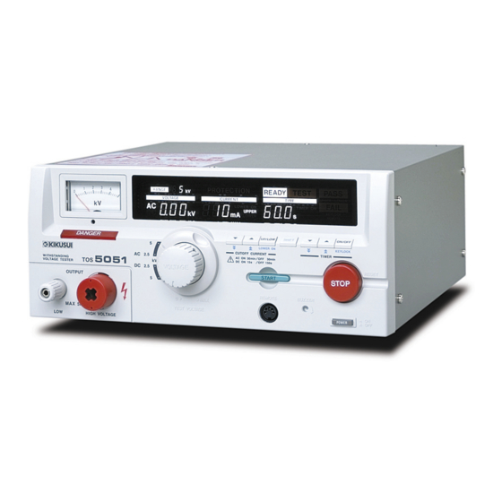
TOS5000 SERIES
WITHSTANDING VOLTAGE TESTER
WARNINGS Against HIGH VOLTAGE
TOS5101
TOS5051
TOS5050
Part No. Z1-000-632 IB000598, MAR/2004
Advertisement
Chapters
Table of Contents


Need help?
Do you have a question about the TOS5101 and is the answer not in the manual?
Questions and answers