Table of Contents
Advertisement
Quick Links
Operation Manual
Charge/Discharge System
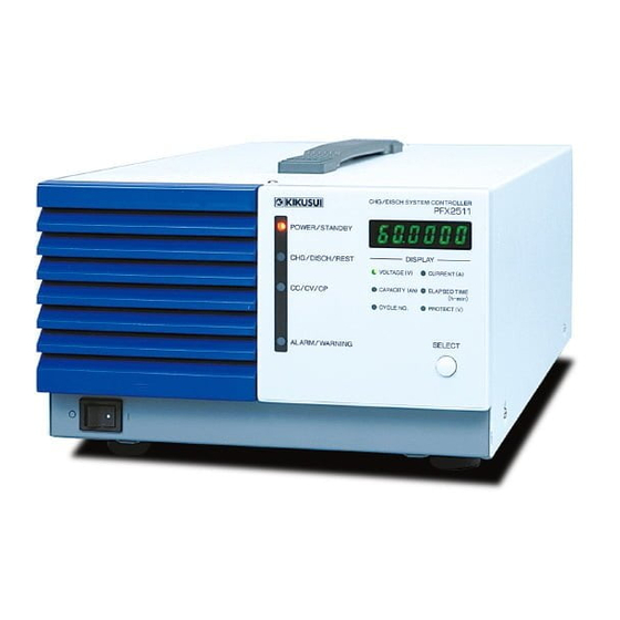
Charge/Discharge System Controller
PFX2500 Series
PFX2511
Communication Control Unit
PFX2121
PART NO. Z1-005-432, I0038801
May 2021
Installation and
Volt / Thermometer Unit
Features of the digital
Description of the Function
Connecting to a Bias Power Supply
Reference Data
Troubleshooting
1
General
Description
2
Preparation
3
Operations
4
Specification
5
OP01-PFX
App.
CC/CV control
7
Meintenance
Advertisement
Table of Contents

Subscribe to Our Youtube Channel
Related Manuals for Kikusui PFX2500 Series


Summary of Contents for Kikusui PFX2500 Series
- Page 1 Installation and Preparation Operations Operation Manual Specification Charge/Discharge System Volt / Thermometer Unit Charge/Discharge System Controller OP01-PFX PFX2500 Series Features of the digital App. PFX2511 CC/CV control Description of the Function Communication Control Unit Connecting to a Bias Power Supply PFX2121...
-
Page 2: About This Manual
If the operation manual gets lost or soiled, a new copy can be provided for a fee. In either case, please contact Kikusui distributor/agent, and provide the “Kikusui Part No. ” given on the cover page. Operation manual has been prepared with the utmost care;... -
Page 3: Checking The Package Contents
(Not all symbols may be used.) If any of the accessories are damaged or missing, contact your Kikusui agent or distributor. We recommend that you keep all packing materials, in case the Indicates that a high voltage (over 1 000 V) is used here. -
Page 4: Safety Precautions
Service Line Voltage • Kikusui service engineers will perform internal service of the Input power product. If the product needs adjustment or repairs, contact your Kikusui distributor or agent. • Use the product within the rated input line voltage range. -
Page 5: Precautions Concerning Installation
• The PFX2511 Charge / Discharge System Controller is also • Avoid locations where the product is exposed to high referred to as the PFX2500 series, PFX2500 or PFX2511 in this temperature or direct sunlight. manual. -
Page 6: Table Of Contents
Contents Volt / Thermometer Unit (Option) About this manual 2 Attaching the Volt / Thermometer Unit 76 Checking the Package Contents 3 Preparation of the DUT (battery) Connection 78 Connecting the DUT (battery) 81 Safety Symbols 3 Volt / Thermometer Unit OP01-PFX Specifications Safety Precautions 4 Precautions When Moving the Product 4 Appe... - Page 7 Search by Topic ➔”Checking the Package Contents” Preparation • What accessories are included in the package? ➔”Applied DC Power Supplies and • How do I know the appropriate system p.16 Electronic Loads” configuration for charge / discharge testing's? ➔”Preparation of the DUT (battery) •...
-
Page 8: Charge / Discharge System Controller Pfx25118
Charge / Discharge System Controller PFX2511 Front panel The color of status indication LED and the operation status Status indication for PFX2511 Green Orange POWER/STANDBY POWER STANDBY CHG/DISCH/REST DISCH REST DISPLAY CC/CV/CP VOLTAGE ( V ) CURRENT ( A ) CAPACITY ( Ah ) ELAPSED TIME ALARM/WARNING ALARM... - Page 9 13 PROTECT (V) LED the SELECT key) p.52 14 SELECT key To select the item to display on the DISPLAY. Rear panel KIKUSUI ELECTRONICS CORP. NC03069-1 MADE IN JAPAN AC INPUT 90-250V 50-60Hz 60VA MAX Example in which a Volt / Thermometer Unit OP01-PFX is installed in slot 1 of a PFX2511.
-
Page 10: Communication Control Unit Pfx2121 (Option)10
TP-BUS2 p.36 ID switch Setting switch for the instrument ID Rear panel TP -- BUS KIKUSUI ELECTRONICS CORP. MADE IN JAPAN Name Function TP-BUS 2 connector A connector for the TP-BUS 2 (Unable to be used when the PFX2511 is p.32... -
Page 11: General Description
General Description This chapter describes the outline of product, connectable equipments, options. -
Page 12: Product Overview
The PFX2511 can be used for the wide range of power ratings combined with the selected model of Kikusui's DC power supply and the Kikusui's Electronic load. The initial cost can be reduced by selecting the equipment applied to the desired testing condition of the charge / discharge test. - Page 13 Product Overview ● 20-value CC / CP Pulse discharge function The PFX2511 can pulse settings can be assigned up to 20 different values, which perform discharge test that simulates a change of the dynamic load current. ● Expandable measurement feature By installing a Volt / Thermometer Unit OP01-PFX, you can expand the number of measurement points by four voltage and four temperature measurement points.
-
Page 14: System Configuration
System Configuration The figure below shows an example of basic configuration of the charge and discharge system using the PFX2511. The system consists of the selected Kikusui's Electronic load and the DC power supply combined with a peripheral subsystem. PFX2511... - Page 15 VISA (Virtual Instrument Software Architecture) is a standard developed by the VXIplug&play Systems Alliance that defines software specifications for communicating with instruments from a PC. KI-VISA is a Kikusui-original VISA library that complies with the VXIplug&play VISA specifications. You can download the latest version of KI-VISA from the Kikusui website (http://www.kikusui.co.jp/en/download/).
-
Page 16: Applied Dc Power Supplies And Electronic Loads
As for the latest information for the system configuration can be confirmed on our website (http:// www.kikusui.co.jp/en). Please contact our distributor or agent for details. The factory default settings are arranged by the following configuration. DC Power supply: PWR800L... - Page 17 Applied DC Power Supplies and Electronic Loads Selecting the system for the DC power supplies and the electronic loads The range is different between the charge operation and the discharge operation state. Select the applicable model of the DC power supply and the Electronic load that meets each requirement. The following graph indicates the range of allowable charge voltage value / current value calculated by the formula specified below.
- Page 18 Applied DC Power Supplies and Electronic Loads The following graph indicates the range of allowable charge voltage value / current value calculated by the formula as specified below. Use the equipment that should not exceed the range of the voltage value (starting discharge voltage value/end voltage value) and the current value (constant current value).
-
Page 19: Options
Options For details on the options, contact your Kikusui agent or distributor. Rack mounting options Product Model Notes Rack mount frame KRA3 Inch rack EIA Standard KRA150 Milli rack JIS standard Unit : mm (inch) Unit : mm KRA150 KRA3 Remove the handle and rubber feet before you mount the product to a rack. - Page 20 Options Load cable TL08-PFX The dedicated load cable for connecting the PFX2511 and the DUT (battery). It makes easier for the connection, because the cable and the sensing cable are assembled. Volt / Thermometer Unit OP01-PFX This is an expansion board for the measurement feature. By installing this board, you can expand the number of measurement points by four voltage and four temperature measurement points.
-
Page 21: Installation And Preparation
Installation and Preparation This chapter describes the procedures of unpacking and preparation of the PFX2511 before use . -
Page 22: Connecting The Power Cord
If the supplied power cord cannot be used because the rated voltage or the plug shape is incompatible, have a qualified engineer replace it with an appropriate power cord that is 3 m or less in length. If obtaining an appropriate power cord is difficult, consult your Kikusui agent or distributor. - Page 23 Connecting the Power Cord To ensure the safety charge and discharge testing, the power cord of the all connected equipments should be connected to the outlet with the same ground terminal. Protect the malfunction in such case when the AC power line is shut down. Connection to the switch board To ensure the safety charge and discharge testing, the AC power line connected with other equipments should be wired to the same AC power line.
-
Page 24: Connection And Setting Of The Each Equipment
Connection and Setting of the Each Equipment The following example is consisting of the Charge/ Discharge System Controller (PFX2511), DC power supply (PWR800L), the Electronic load (PLZ1004W), and the DUT (battery). The direction of leading cables of input / output terminal board can be either right or left angle. However, wire the all the cables to become same directions as possible. - Page 25 Connection and Setting of the Each Equipment The following shows an example of system configuration which consist of 1set of the Charge/ Discharge System Controller (PFX2511), 1 set the DC power supply (PWR1600L), and 2sets of the Electronic load (PLZ1004W) in parallel operation. As for the parallel operation of the Electronic load units (PLZ1004W), locate the master unit with a position nearest to the PFX2511.
- Page 26 Connection and Setting of the Each Equipment Terminal cover Remove the terminal cover Connect the PFX2511 to the DC power supply. p. 27 Use the cable with a crimp terminal which comes with the PFX2511 as a standard accessory. Connect the PFX2511 to the Electronic load. p.
-
Page 27: Connecting With The Dc Power Supply
Connect the PFX2511 to the DC power supply using the cable with the crimp terminal and the 26- core flat cable. The following procedure refers to the case of connecting Kikusui's Regulated DC power supply PWR800L. Connecting the cable with the crimp terminal Confirm that the POWER switch of all connected equipments are turned off. - Page 28 Connecting with the DC Power Supply Fix them in place using the screws. Check that the screws are securely fastened. Top cover Attachment of the Align the top and bottom parts of the terminal cover and screw OUTPUT terminal cover them in place.
-
Page 29: Connecting With The Electronic Load
Connect the PFX2511 to the Electronic load using the cable with the crimp terminal and the 20- core flat cable. The following procedure refers to the case of connecting Kikusui's Electronic load PLZ1004W. Connecting the cable with the crimp terminal Confirm that the POWER switch of all connected equipments are turned off. - Page 30 Connecting with the Electronic Load φ10 line Cut the sleeve to φ15 line φ20 line match the wire Bolt (M8 x 18) φ25 line diameter by using Tightening torque: 11.22 N ・ m the gauge as a Spring washer (M8) reference.
- Page 31 Connecting with the Electronic Load Connecting the flat cable Attach the lock lever and core to the 20-core flat cable. (those items come with p. 28 the PFX2511 as standard accessories) If the lock lever is not attached, the connector may come off. Confirm that the POWER switch of all connected equipments are turned off.
-
Page 32: Using Bpchecker2000 To Control The Pfx2511
Total length: 25 m or less (Between the devices at the ends of the bus) TP--BUS Communication Control Unit PFX2121 KIKUSUI ELECTRONICS CORP. MADE IN JAPAN TP-BUS 2 TP-BUS 1 Cannot be used Node numbers: 1 to 15 when the PFX2511 is connected... - Page 33 The PFX2121 Communication Control Unit is a dedicated controller of the PFX2000 series and the PFX2511. You cannot use it to control other Kikusui devices that have TP-BUS interfaces. TP-BUS connector wiring The TP-BUS connector can be connected or disconnected even when the power of equipments are...
- Page 34 Using BPChecker2000 to Control the PFX2511 ■ Wires and tools required for connection Wires Model: CMX/ 2464-1061/ 2A-SB LF AWG24 2CORE, 25 m or less Manufacture: Taiyo Cabletec Corporation Axis diameter : ϕ3, End width : 2.6 mm Flat-blade screwdriver Wire stripper Wire stripper suitable for the wires described above.
- Page 35 PC PFX2121 Communication control unit To the To the USB port USB port TP--BUS KIKUSUI ELECTRONICS CORP. MADE IN JAPAN Personal computer Core ■ Connect the USB cable through the USB hub PFX2121 Core Communication control unit TP--BUS...
- Page 36 Using BPChecker2000 to Control the PFX2511 USB driver for PFX2121 A dedicated USB driver must be installed in the PC for the PC to identify the PFX2121 on the USB. Help The driver software is included in the BPChecker2000. Hardware Config Wizard Setting the instrument ID If the PC has multiple USB ports or if you are using a self-powered USB hub, you can connect up to two PFX2121 on a single USB.
-
Page 37: Setting The Dc Power Supply
Setting the DC Power Supply Set the protection function to protect the DUT (battery) and the connected equipments. Set the external analog control to control the PFX2511. It is recommended to set the lock function when all the settings are completed. It prevents from PWR series being changed of setting by the operational error. -
Page 38: Setting The Electronic Load
Setting the Electronic load Setting the external analog control Set the item concerning the external analog control to the following condition by using the CONFIG setting. Model CV control source settings CC control source settings External control logic setting of the output on/off PWR series External voltage control External voltage control... - Page 39 Setting the Electronic load Setting the protection functions If the unit of the PLZ-4W series is set as the factory default settings, it is not necessary to set the protection function. Especially, when the DUT is concerned the safety as a matter of high priority or the charge and discharge test is conducted with a risk, the level of safety can be improved by the setting of protection functions.
- Page 40 Setting the Electronic load Setting the external analog control Set the item concerning the external analog control to the following condition by using the Menu setting. •Response Menu > Setup > Response : 1/2 •External voltage control Menu > Configuration > External > Control : V •External control logic setting Menu >...
-
Page 41: Setting The Pfx2511
Setting the PFX2511 The following settings can be done by the S1 switch on the rear panel. If you changed the settings, turn on the power of the PFX2511 again. • TP-BUS termination • Node number • The vibration sensor Switch position status of factory default Signal name Logic... - Page 42 Setting the PFX2511 Setting the TP-BUS termination If the TERMN OFF switch is not set properly. Communications become unstable and erroneous operation may result. Setting example for the 3 channels of charge and discharge unit connected with the PFX2121 by the TP-BUS termination Each end of the TP-BUS [Charge and discharge unit 3] DC power...
- Page 43 Setting the PFX2511 Setting the node number Assign the specific address called the node number to the connected PFX2511 on the TP-BUS. Specify a different value for each channel of the charge and discharge unit. Connect the PFX2511 to the TP-BUS1 connector of the PFX2121. p.
-
Page 44: Preparation Of The Dut (Battery) Connection
Preparation of the DUT (battery) Connection Standard accessories of the PFX2511 does not include the cable for connecting to the DUT (battery). Prepare the cable applied to description of the DUT (battery). The cable used for the charge / discharge current between the •... - Page 45 ■ Nominal cross-sectional area of cables and allowable currents (reference) Nominal cross- (Reference cross- Allowable Current sectional area sectional area) recommended current [A] (Ta = 30 °C) by Kikusui [A] (2.08) (3.31) (5.26) (8.37) (13.3) (21.15) (33.62) (42.41) (53.49) (67.43)...
- Page 46 Preparation of the DUT (battery) Connection Making the sensing cable Pin No. Symbol Description + S Positive voltage terminal. Connect to the positive terminal of the DUT (battery). - S Negative voltage terminal. Connect to the negative terminal of the DUT (battery). +...
-
Page 47: Connecting The Dut (Battery)
Connecting the DUT (battery) Possible electric shock. WARNING • After connecting the devices, connect the PFX2511 to the DUT (battery). Connect the PFX2511 side first. • When installing the fuse between the PFX2511 and the DUT (battery), make sure that the POWER switch is turned off and unplug the AC power cable from the outlet. - Page 48 Connecting the DUT (battery) Connecting the DUT cable Confirm the status of POWER switch of the PFX2511 whether it is turned off or being in the STANDBY position. Even when the POWER switch is turned on, the DUT cable and the sensing connector can be disconnected only in the "STANDBY"...
-
Page 49: Operations
Operations This chapter describes the turning on the power, the panel operation, the external control monitoring, protection functions, alarms and setting of the model ID's. -
Page 50: Turning On And Off Of The Power Supply
Turning On and Off of the Power Supply There is no specific order to turn on the power of equipments in the system (the PFX2511, DC power supply, Electronic load, and other peripherals that compose the system), and also there is no order for when turn off the power of equipments. - Page 51 Turn off the POWER switch of the PFX2511. It is possible to turn on and off of the power for all equipments at the same time by customizing the system. If you need assistance, please contact Kikusui agent or distributor. PFX2511/PFX2121...
-
Page 52: Panel Operation
Panel Operation You can select the function to show the value on the display by the SELECT key on the front panel. The display can be changed by pressing the SELECT key. When the power is turned on, the display shows the voltage value. PFX2511 Example when the voltage indication is selected DISPLAY VOLTAGE (V) - Page 53 Outline of the External Control External alarm common STRIP - GAUGE External alarm input AWG 24 Status common 10mm ALM status END status The wire is directly The wire scrap REST status incontact with the is in contact with chassis. the chassis.
-
Page 54: Protection Functions And Alarms
Protection Functions and Alarms When the protection function interrupts or the alarm occurs while the test, either turning off the output or illuminate the "ALARM/WARNING" LED (in red or orange) and interrupts testing. The warning function is activated when a test is not being executed. In this case, the ALARM / WARNING LED lights orange. - Page 55 Cell over temperature / DUT (battery) over temperature protection When the error code No.200's (Err.2xx) is displayed, it is an occurrence of an internal error. Confirm the displayed error code, and contact Kikusui agent or distributor. Releasing the alarm The alarm can be released from the application software BPChecker2000. Transmit the alarm Help release command after eliminating the cause of alarm occurrence indicated by the error code.
-
Page 56: Setting The Model Id
If you cannot clear the warning even when all of the causes of the warning occurrence are eliminated, the PFX2511 may have malfunctioned. If this happens, stop using the PFX2511 and contact your Kikusui agent or distributor. Setting the Model ID The operating range of charge and discharge (maximum voltage / maximum current) for the p. -
Page 57: Test Procedure
Test Procedure To perform charge/discharge tests, use BPChecker2000 for the PFX2511 to configure settings such as the information of the connected devices and the test conditions. When the test is executed for the first time, follow the instruction specified below. BPChecker2000 test procedure Configuration of the hardware. - Page 58 This page is intentionally blank. PFX2511/PFX2121...
-
Page 59: Specification
Specification This chapter contains PFX2511 specifications, outline drawings and Commu- nication control unit PFX2121 (sold sepa- rately) specifications. -
Page 60: Pfx2511 Functional Specifications
PFX2511 Functional Specifications • Static: General term to indicate CC charge, CC - CV charge, CC discharge, and CP discharge • Pulse: General term to indicate pulse CC discharge and pulse CP discharge Charge function Static Constant current / Settings Constant current value (Current) Constant voltage Constant voltage value (CV Voltage) - Page 61 Specification Discharge function Static Constant current Settings Constant current value (Current) discharge Cutoff condition Specified time after discharge start (Discharge Time) Battery voltage (Cutoff Voltage) Rest Specified time after discharge end (Rest Time) Constant power Settings Constant power value (Wattage) discharge Limit current (Limit Current) Cutoff condition Specified time after discharge start (Discharge Time)
- Page 62 Specification Measurement function Static Battery voltage Average voltage of the every 500 ms Charge / discharge current Average current of the every 500 ms Battery temperature Simplified temperature measurement function using a thermistor as a temperature sensing element (Temperature) Capacity The product of the measured current (average current) and the elapsed time The scale of power...
- Page 63 Specification Protection function Overvoltage Software OVP Detection of the overvoltage (overcharge) by the measured value of (overcharge) voltage (the AD converted value) protection Output off Hardware OVP Direct detection by the hardware comparator Output off Undervoltage Software UVP Detection of the undervoltage (overdischarge) by the measured value of (overdischarge) voltage (the AD converted value) protection...
- Page 64 / cycle numbers / protection functions/ alarm information / etc.) Interface DC power supply I/F Exclusive connector for Equipped 1 channel, 26 pin connector, isolation input / output Kikusui's product Electronic load I/F Exclusive connector for Equipped 1 channel, 20 pin connector, isolation input / output Kikusui's product...
-
Page 65: Pfx2511 Electrical Specifications
PFX2511 Electrical Specifications Unless specified otherwise, the specifications are for the following settings and conditions. • The warm-up time is 30 minutes. • TYP (typical) values do not guarantee the performance. • reading: Indicates the readout value. • set: Indicates the setting value. •... - Page 66 Specification Setting accuracy Static Constant current 0.000 A to 50.000 A Range charge / discharge Accuracy Resolution 1 mA Constant voltage 0.000 V to 60.000 V Range charge / discharge Accuracy Resolution 1 mV Constant power 0.1 W to 3000.0 W Range discharge *2 *4...
- Page 67 Specification Measurement accuracy Static Charge / Range 0.0000 A to 50.0000 A discharge Current *1 *2 ±(0.15 % of reading + 0.02 % of rating) Accuracy measurement Resolution 0.1 mA Voltage Range -6.0000 V to 60.0000 V measurement *1 *2 ±(0.05 % of reading + 0.02 % of rating) Accuracy Resolution...
- Page 68 Specification Temperature measurement The thermistor 103AT-2 (Ishizuka denshi) is used for the temperature sensor. Resistance (temperature) measurement section -40.0 ° to 100.0 ° Measurable range 0.1 ° Measurement resolution ±0.5 ° (Measuring temperature at 0 ° to 40.0 ° *2 *3 Measurement accuracy ±1 °...
- Page 69 Specification Protection function Overvoltage (overcharge) protection Software 0 % to 105 % of the rated value Range ±(0.05 % of set + 0.02 % of rating) *1*2 Accuracy Resolution 1 mV Time to trip 150 ms maximum Hardware 0 % to 110 % of the rated value Range *1*2 ±0.5 % of rating...
- Page 70 Specification General specifications Nominal input rating 100 Vac to 240 Vac, 50 Hz / 60 Hz Input voltage range 90 Vac to 250 Vac Power consumption 60 VAmax When three OP01-PFX units are installed: 80 VAmax 0 °C to 40 °C Operating temperature and humidity ranges (32 ºF to 104 ºF) , 20 %rh to 85 %rh (no condensation) -10 °C to 60 °C...
- Page 71 Specification This is a Class A equipment. The PFX2511 is intended for use in an industrial environment. This product may cause interference if used in residential areas. Such use must be avoided unless the user takes special measures to reduce electromagnetic emissions to prevent interference to the reception of radio and television broadcasts.
-
Page 72: Communication Control Unit Pfx2121 (Option) Specifications
Communication Control Unit PFX2121 (option) Specifications Specification of the product that have the CE mark on their panels. Display function Indication of the POWER Blinked "POWER" LED (Green) Power supply Indicates the supplied power from the bus line (Connected with the USB) Illuminated "POWER"... - Page 73 Specification General specifications Power 5 V, 300 mA or less, Receiving power from the USB 0 °C to 40 °C Operating temperature and humidity ranges (32 ºF to 104 ºF) 30 %rh to 80 %rh (no condensation) -10 °C to 60 °C Storage temperature and humidity ranges (14 ºF to 140 ºF) 20 %rh to 80 %rh...
- Page 74 This page is intentionally blank. PFX2511/PFX2121...
-
Page 75: Volt / Thermometer Unit (Option)
OP01-PFX Volt / Thermometer Unit (Option) This chapter describes how to install the optional Volt / Thermometer Units OP01-PFX and how to connect the DUT (battery) and bias power supply to the units and contains the specifications of the units. -
Page 76: Attaching The Volt / Thermometer Unit
Attaching the Volt / Thermometer Unit When you want to expand the number of voltage and temperature measurement points, you can install Volt / Thermometer Unit OP01-PFXs in the rear-panel option slots. After you remove a Volt / Thermometer Unit, attach a slot cover over the empty slot using screws. The number of channels that you can connect to the charge and discharge unit differs depending on whether OP01-PFX units are installed in the PFX2511. - Page 77 Attaching the Volt / Thermometer Unit The first time that you install the OP01-PFX after you purchase it, use the Help application software BPChecker2000 to customize the model ID. Hardware Config Wizard Remove the cover Insert the board Connector section Attachment of the OP01-PFX PFX2511/PFX2121...
-
Page 78: Preparation Of The Dut (Battery) Connection
Preparation of the DUT (battery) Connection Cables for connecting the OP01-PFX and the input terminal to the DUT (battery) are not included with the OP01-PFX. Prepare the cable applied to description. The cable used for the charge / discharge current •... - Page 79 ■ Input terminal (Connector MC1.5/10-G : Phoenix Contact) When the PFX2511 is shipped from the factory, connectors are attached to the input terminals. If they are damaged or lost, 84-61-7910 contact your Kikusui agent or distributor. Temperature measurement (THERMOCOUPLE) Term No. Signal...
- Page 80 Preparation of the DUT (battery) Connection Connecting the thermocouple for connector plug Connect type K thermocouples directly to the connector plug. Insert the wire with 7 mm of the covering removed here. Thermocouple Thermocouple 4 Thermocouple 3 Thermocouple 2 Thermocouple 1 Temperature Sensing Length up to 5 m The attached...
-
Page 81: Connecting The Dut (Battery)
Connecting the DUT (battery) Possible electric shock. WARNING • When installing the fuse between the OP01-PFX and the DUT (battery), make sure that the POWER switch is turned off. • There is no order for wiring between the connecting equipments, however, the wiring with the DUT (battery) must be arranged at the last and it should be connected from the side of OP01-PFX. -
Page 82: Volt / Thermometer Unit Op01-Pfx Specifications
Volt / Thermometer Unit OP01-PFX Specifications Items not listed below conform to the specifications of the PFX2511. • reading: Indicates the readout value. • set: Indicates the setting value. • rating: Indicates the rated. • Static: General term to indicate CC charge, CC - CV charge, CC discharge, and CP discharge •... - Page 83 Volt / Thermometer Unit OP01-PFX Specifications Cell measurement function Static Cell voltage Average current of the every 500 ms (Cell Voltage) Cell temperature Temperature measurement function using a thermocouple as a temperature sensing element, updated every second (Cell Temperature) Pulse Cell voltage Maximum voltage and minimum voltage in one cycle (Cell Peak Point).
- Page 84 Volt / Thermometer Unit OP01-PFX Specifications Cell voltage measurement Static Number of measurement terminals 4 -2.0000 V to 20.0000 V Measurable range ±(0.05 % of reading + 0.02 % of rating) Measurement resolution Accuracy 0.1 mV Measurement value Average voltage of the every 500 ms Measurement interval 500 ms Pulse...
- Page 85 Volt / Thermometer Unit OP01-PFX Specifications General specifications Performance when the OP01-PFX is installed in the PFX2511. Input terminal ⇔ chassis Isolation ±500 Vmax voltage Insulation 30 MΩ or greater at 500 Vdc, 70 %rh or less *1 Input terminal ⇔ DUT terminal resistance Input terminal ⇔...
- Page 86 This page is intentionally blank. PFX2511/PFX2121...
-
Page 87: A Features Of The Digital Cc/Cv Control88
Appendix A Features of the Digital CC/CV Control B Description of the Function C Connecting a Bias Power Supply D Reference Data E Troubleshooting F Maintenance... - Page 88 Features of the Digital CC/CV Control The digital control is adopted to control the operation of constant current (CC) and the constant voltage (CV) . To perform the efficient evaluation test, the following describes the feature and the principle of operation for the digital control of the CC/CV operation .
- Page 89 Features of the Digital CC/CV Control When the connected DUT is other than the battery, there is a possibility that the operation of the CC / CV control may not be functioned properly. When at no load (no connection) or the connected battery with the internal impedance at abnormally high, the CV operation may not be activated normally.
-
Page 90: B Description Of The Function
Description of the Function The following describes the outline and the direction for the measurement features and other func- tion of PFX2511, charge/Discharge System Controller. Description of the measurement function The PFX2511 equips the high-speed, a 24-bit delta-sigma analog-to-digital converter (ADC). It enables to perform a wide range of the measurement in 60 V / 50 A without switching the range with a resolution of 100 μV / 100 μA in high-speed and high-accuracy. - Page 91 Description of the Function Measurement for the operation of pulse discharge When in the state of pulse discharge operation, the measured value of 1 ms is acquired as well as measurement of the normal operation. As for the pulse voltage measurement, the measurement is executed by the pre-specified pulse.
- Page 92 Description of the Function In this case, the calculation of average current is adding the integration of the actual measurement pulse current value until reaching to the unit time and the pulse time width. And the average current value can be calculated in division by the unit time from the added value when reaching at the unit time.
- Page 93 Description of the Function Unbalance detection function (only when an OP01-PFX is installed) This function measures the voltages of all the cells in the object under measurement, and detects the maximum and minimum cell voltages. When the unbalance voltage (the difference between the maximum and minimum cell voltages) exceeds the set value, an alarm occurs and the output is turned off.
-
Page 94: C Connecting A Bias Power Supply
This is useful when you want to evaluate a low voltage range, when you want to perform a charge/ discharge test on a single cell, or in similar situations. For the bias power supply, you can use variable-voltage power supplies such as the Kikusui PAS series, PWR series, and PAG series or fixed-voltage power supplies. -
Page 95: D Reference Data
Reference Data PFX2511 pulse discharge The data acquired under the following conditions. System requirement Charge/ discharge system controller PFX2511 Power supply PWR800L Electronic load PLZ1004W The DUT (battery) Connecting the PWR1600L by the 14 mm cable with length of 5 m long. (at the operation of 10 V in CV mode) App. -
Page 96: Troubleshooting
If your problem does not correspond to any of the listed items, If you carry out the corrective action but the situation does not improve, contact your Kikusui agent or distributor. Symptom concerning Charge / Discharge System Controller PFX2511 The power does not turn on. - Page 97 70 clogged dust filter, etc. p. 101 When the LED illuminates even any abnormal operation environment is found, stop the operation immediately and contact Kikusui distributor/agent. The alarm was occurred in the connected Electronic load. Confirm on the front It displays p.
- Page 98 Troubleshooting Problem Items to check and corrective actions The overshoot is occurred on Is the Electronic load is properly arranged? the pulse current. Confirm that the setting is correctly arranged as follows. p. 40 Menu > Setup > Response : 1/2 SLEW RATE settings : Maximum value.
- Page 99 App. When the error becomes large under any condition, it is concerned - that the adjustment may be shifted. Contact Kikusui distributor/agent. The voltage display is unstable. When the DUT other than battery is connected, or any other device connected with the DUT, the indication of the voltmeter may not be -...
- Page 100 Troubleshooting Symptom concerning Communication control unit PFX2121 The power does not turn on. Problem Items to check and corrective actions The "POWER" LED doesn't blink Is the power of the PC turned on? even when the PFX2121 is Has the OS completely been activated? p.
-
Page 101: Maintenance
Maintenance Cleaning the dust filter Possible electric shock. When performing maintenance work, be sure to turn off the POWER WARNING switch and remove the power cord plug. Dust filters are furnished on the inside of the louver. Periodically clean the filter to prevent clogging. App. - Page 102 This page is intentionally blank. PFX2511/PFX2121...
- Page 103 INDEX front panel PFX2121 ................10 accessory ....................3 PFX2511 ................8 alarm occurrence ..............43 release ................55 ground ..................... 22 application software ..............14 ID switch ..................36 BPChecker2000 ................14 instrument ID ................. 36 Connection ..............32 LED display ..............52 cell voltage sensing cable ............
- Page 104 Connect ................48 making ................46 Sensing cable set TL09-PFX ................20 DC power supply ............37 Electronic load ..............38 PFX2121 ................36 PFX2500 series ..............41 Storage humidity range PFX2121 ................5 PFX2511 ................5 Storage temperature range ............5 temperature chamber ..............15 synchronized testing ............15 temperature sensing cable ..........44...
- Page 105 KIKUSUI ELECTRONICS CORP. 1-1-3 Higashiyamata, Tsuzuki-ku, Yokohama, 224-0023, Japan Phone: +81-45-482-6353 Facsimile: +81-45-482-6261 www.kikusui.co.jp/en/...
Need help?
Do you have a question about the PFX2500 Series and is the answer not in the manual?
Questions and answers