Table of Contents
Advertisement
Quick Links
Communication
Interface Manual
Withstanding Voltage Tester
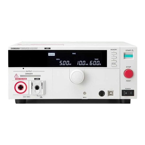
TOS5200
DANGER
This product generates high voltage!
Improper operation can lead to serious accidents.
To prevent accidents, be sure to read the section
"Safety Precautions during Testing" in this manual.
Keep this manual close to the product so that the
operators can read the manual at any time.
PART NO. IB028024
Jul. 2016
Remote Control 5
Remote Control Overview 6
Installing the VISA Library 7
Using the USB Interface 8
Using the RS232C Interface 9
Message Overview 13
Message Overview 14
Command Reference 19
Command Description in This Manual 20
IEEE 488.2 Common Commands 21
Test Mode Settings 24
AC Withstanding Voltage Test
About Sequences 29
Test Execution (SEQuence2:TEST) 31
Querying Measured Values
(SEQuence1:ACQuire) 33
Various Settings 37
Status Register and Status Report
IEEE 488.2 Register Model 42
SCPI Register Model 44
TOS5050A Commands 52
List of Messages 58
Command Processing Time 67
Using Visual Basic 2008 68
1
2
Talk Mode 11
Conditions 25
7
Function 40
8
Tutorial 56
App
Appendix 57
List of Errors 63
Default State 66
Advertisement
Table of Contents

Related Manuals for Kikusui TOS5200


Summary of Contents for Kikusui TOS5200
- Page 1 Message Overview 14 Command Reference 19 Command Description in This Manual 20 Withstanding Voltage Tester IEEE 488.2 Common Commands 21 Test Mode Settings 24 TOS5200 AC Withstanding Voltage Test Conditions 25 About Sequences 29 Test Execution (SEQuence2:TEST) 31 Querying Measured Values...
-
Page 2: About The Manuals
Manual construction Notations Used in This Manual ■ Setup Guide • The TOS5200 Withstanding Voltage Tester is also referred This manual is intended for first-time users of the product. It to as the TOS5200. gives an overview of the product, connecting procedures, •... -
Page 3: Table Of Contents
Contents About the Manuals ....................2 Notations Used in This Manual ................2 Remote Control Remote Control Overview ...................... 6 Installing the VISA Library ...................... 7 Using the USB Interface......................8 Using the RS232C Interface....................9 Talk Mode..........................11 Message Overview Message Overview....................... - Page 4 Appendix A List of Messages ................58 B List of Errors ................63 C Default State ................66 D Command Processing Time ............67 E Using Visual Basic 2008 ............68 Index............71 TOS5200_INTERFACE...
-
Page 5: Remote Control
Remote Control This chapter provides a general explanation of the remote control function. -
Page 6: Remote Control Overview
Remote Control Overview In addition to controlling the TOS5200 from the front panel, you can control it remotely through the following interfaces. • USB interface • RS232C interface You cannot use the USB and RS232C interfaces at the same time. -
Page 7: Installing The Visa Library
• If NI-VISA or Agilent VISA is already installed on your PC, you do not need to install KI- VISA. KI-VISA is an original VISA library developed by Kikusui Electronics Corporation that sup- ports the VXIplug&play VISA specifications. You can download the most recent version of this library from the Kikusui Electronics Corporation website (http://www.kikusui.co.jp/en/... -
Page 8: Using The Usb Interface
• Complies with USBTMC specification 1.0 and USBTMC-USB488 specification 1.0 • Baud rate: 12 Mbps maximum (full speed) • VID (vendor ID): 0x0B3E • PID (product ID): 0x1046 Service request The TOS5200 is equipped with service request and serial polling functions. TOS5200_INTERFACE... -
Page 9: Using The Rs232C Interface
Using the RS232C Interface The TOS5200 RS232C port is a standard D-sub, 9-pin male connector. Check that the TOS5200 and your PC are off, and connect them with a standard crossover cable (null-modem cable). Use a D-sub, 9-pin, female-to-female AT crossover cable. The port pinout is shown below. - Page 10 The break signal is used as a substitute for the IEEE488.1 dcl/sdc (Device Clear, Selected Device Clear) message. To use the RS232C interface, a “SYSTem:REMote” command must be sent to set the TOS5200 to remote mode. To use remote programming, send “SYSTem:REMote” at the beginning of the program. TOS5200_INTERFACE...
-
Page 11: Talk Mode
Talk mode setting [0: OFF, 1: ON] • If the TOS5200 is initialized, the talk mode is set to “0.” • Even when the talk mode is set to “0” with the *RST command, it will return to the setting specified by the panel when the TOS5200 is restarted. - Page 12 This page is intentionally blank. TOS5200_INTERFACE...
-
Page 13: Message Overview
Message Overview This chapter gives an overview of remote control messages. It then explains topics such as the make-up of the SCPI com- mands that are used for remote control and the command syntax. -
Page 14: Message Overview
The messages that the PC sends to the TOS5200 are commands. The messages that the TOS5200 sends to the PC are responses. Commands are used to execute functions or change settings on the TOS5200 or to query its settings or status. Responses are used to return the product’s settings or status. - Page 15 Do not include the [ and ] symbols in the actual program. Queries You can query the TOS5200 settings and status. To make a query, append a question mark to the end of the program header section. If the query has parameters, insert a space after the question mark, and then write the parameters.
-
Page 16: Parameters
Parameters The SCPI parameter format is derived from the program parameter format that is defined in IEEE 488.2. The program data expression format that the TOS5200 uses is shown below. Non-numeric parameters The TOS5200 uses the following three parameter types. - Page 17 Numeric You can also use units such as V, A, and S in numeric parameters. If a value that cannot be assigned is entered, the TOS5200 rounds the value to the closest possible value. Example: SYSTem:CONFigure:BEEPer:VOLume:PASS 2.0 SYST:CONF:BEEP:VOL:PASS must be set to a value from 0.0 to 0.9, so even if you attempt to set the value to 2.0, it will be set to 0.9.
- Page 18 Message Overview This page is intentionally blank. TOS5200_INTERFACE...
-
Page 19: Command Reference
Command Reference This chapter explains topics such as command details and registers. -
Page 20: Command Description In This Manual
Command Description in This Manual In this manual, SCPI commands are described in the following manner. Commands that have these marks are affected Append the value that you want to set the when an *RST or *RCL command is sent. The setting to after the command. -
Page 21: Ieee 488.2 Common Commands
10.12 Command *ESR? Response Returns the value of the event status register in <NR1> format and clears the register. *IDN Queries the model name, serial number, and firmware version of the TOS5200. IEEE 488.2-1992 section 10.14 Command *IDN? Response The response to *IDN? is indicated below. - Page 22 *OPC? Response Returns “1” when all the commands that are in standby have been processed. *OPT Queries the options that are installed in the TOS5200. This command performs the same function as the SYSTem:OPTion? command. Command *OPT? Response Returns “0” if no options are installed. Returns one of the following responses in <character>...
- Page 23 IEEE 488.2 Common Commands *RST Aborts test execution and measurement and resets the panel settings to their default values. p. 66 For the commands that are affected by *RST, see “Default State”. IEEE 488.2-1992 section 10.32 Command *RST *SAV Saves the present settings to memory. The settings that are saved are the same as those p.
-
Page 24: Test Mode Settings
This is a substitute command for the IEEE 488.1 get message (Group Execute Trigger). If the IEEE 488.2-1992 section 10.37 TOS5200 is in a state in which it does not accept triggers, an SCPI error (-211, “Trigger ignored”) occurs. Command *TRG *TST Executes a self-test. -
Page 25: Ac Withstanding Voltage Test Conditions
AC Withstanding Voltage Test Conditions These are commands for setting the AC withstanding voltage test conditions. Measurement mode setting SENS:MODE * RST Sets the measurement mode. Command SENSe[:ACW]:MODE {RMS|AVE} SENSe[:ACW]:MODE? Parameter Value: True rms response (default) Mean-value response Response Returns the measurement mode in <character> format. Test voltage setting SOUR:VOLT * RST... -
Page 26: Upper Limit Setting
AC Withstanding Voltage Test Conditions Upper limit setting SENS:JUDG * RST * RCL Sets the upper limit that is used in judgments (UPPER). Command SENSe[:ACW]:JUDGment[:UPPer] {<numeric>|MIN|MAX} SENSe[:ACW]:JUDGment[:UPPer]? {MIN|MAX} Parameter Value: 0.01 m to 110 m (The default value is 0.02 m.) Unit: Response Returns the upper limit in <NR3>... -
Page 27: Test Time Setting
AC Withstanding Voltage Test Conditions Test time setting SOUR:VOLT:TIM * RST * RCL Sets the test time (TIMER). This setting is enabled when SOUR:VOLT:TIM:STAT is set to ON. Command SOURce[:ACW]:VOLTage:TIMer {<numeric>|MIN|MAX} SOURce[:ACW]:VOLTage:TIMer? {MIN|MAX} Parameter Value: 0.1 to 999.0 (The default value is 0.1.) Unit: Response Returns the test time in <NR3>... -
Page 28: Voltage Rise Time Setting
AC Withstanding Voltage Test Conditions Voltage rise time setting SOUR:VOLT:SWE:TIM * RST * RCL Sets the voltage rise time (Rise Time). Command SOURce[:ACW]:VOLTage:SWEep[:RISE]:TIMer {<numeric>|MIN|MAX} SOURce[:ACW]:VOLTage:SWEep[:RISE]:TIMer? {MIN|MAX} Parameter Value: 0.1 to 10.0 (The default value is 0.1.) Unit: Response Returns the voltage rise time (Rise Time) in <NR3> format. Voltage fall time setting SOUR:VOLT:SWE:FALL:TIM:STAT * RST... -
Page 29: About Sequences
If you send the ABOR, *RST, or *RCL command, the trigger sub- system is switched to the IDLE state, regardless of its current state. If you send the TRG command while the TOS5200 is in the IDLE state, tests will not be per- formed. - Page 30 PASSED? PASS PASSED FAILED PASS HOLD time elapses The TOS5200 has the following two trigger functions. • SEQuence1 (ACQuire) Starts measurements and queries measured values. • SEQuence2 (TEST) Executes tests. You have to specify the execution conditions in advance. TOS5200_INTERFACE...
-
Page 31: Test Execution (Sequence2:Test)
Test Execution (SEQuence2:TEST) This function executes tests. You have to specify the execution conditions in advance. If the double action feature or momentary feature is set to ON, tests do not start even when you send trigger commands. In the panel CONFIG settings, set the double action feature or momentary feature to OFF. TRIG:SEQ2:SOUR/ TRIG:TEST:SOUR * RST Sets the trigger source to apply to the SEQuence2 (TEST) group. - Page 32 If you send an ABOR command while the TOS5200 is executing tests or measurements, the measured data is discarded. If you send an ABOR command without first sending an INIT command and if the measure- ment data that is held in the TOS5200 is valid, the measured data is not discarded. Command ABORt TEST:PROT:CLE Clears the protection mode.
-
Page 33: Querying Measured Values (Sequence1:Acquire)
If you send an ABOR command without first sending an INIT command and if the measure- ment data that is held in the TOS5200 is valid, the measured data is not discarded. Command ABORt MEAS:CURR/ READ:CURR Starts a new measurement and queries the current. - Page 34 Querying Measured Values (SEQuence1:ACQuire) MEAS:VOLT/ READ:VOLT Starts a new measurement and queries the voltage. Command MEASure[:ARRay]:VOLTage? READ[:ARRay]:VOLTage? Response Returns the measured voltage in <NR3> format or the measured voltages as a comma- separated list in <NR3>,<NR3>,... format. Unit: MEAS:TIME/ READ:TIME Starts a new measurement and queries the elapsed test time.
- Page 35 Querying Measured Values (SEQuence1:ACQuire) INIT:SEQ1/ INIT:NAME ACQ Begins a new measurement (starts the trigger function). Measurement is started by the trigger source set with TRIG:SOUR. Command INITiate[:IMMediate]:SEQuence1 INITiate[:IMMediate]:NAME ACQuire TRIG Executes a software trigger for the SEQuence1 (ACQuire) group. Command TRIGger[:SEQuence[1]][:IMMediate] TRIGger[:ACQuire][:IMMediate] FETC:CURR Queries the measured current without starting a new measurement.
- Page 36 Querying Measured Values (SEQuence1:ACQuire) Queries the results of the previous test. Command RESult[:IMMediate]? Response Returns the following results of the previous test: test number, program number, test mode, test start ti Response me, voltage, current, resistance, test time, and judgment result. Each result is separated by a comma in the following format: <NR1>, <NR1>,<character>, <NR1>, <NR3>, <NR3>, <NR3>, <NR3>, <character>.
-
Page 37: Various Settings
Various Settings PASS judgment result hold time setting SYST:CONF:PHOL * RST Sets the length of time that a PASS judgment result will be held (Pass Hold). Command SYSTem:CONFigure:PHOLd {<numeric>|MIN|MAX|INFinity} SYSTem:CONFigure:PHOLd? {MIN|MAX} Parameter Value: 50 m, 100 m, 200 m, 1, 2, 5 (The default value is 50 m.) INFinity The PASS judgment result is held indefinitely (HOLD). -
Page 38: Other Settings
Returns the key lock status in <NR1> format. SYST:LOC Switches the TOS5200 to local mode (panel operation). This is a substitute command for the IEEE 488.1 REN message (Remote Disable). You can switch the TOS5200 back to remote mode by sending the SYST:REM or SYST:RWL command. - Page 39 (including those of the LOCAL key) are locked. This is a substitute command for the IEEE 488.1 REN (Remote Enable), address specification, and llo (Local Lock Out) messages. You can switch the TOS5200 back to local mode by sending the SYST:LOC command. If you send the SYST:REM command, you can use the LOCAL key.
-
Page 40: Status Register And Status Report Function
In each SCPI status register, there are the following sub registers: the CONDition register, the EVENt register, the ENABle register, the PTRansition filter, and the NTRansition filter. CONDition register The CONDition register transits automatically and reflects the condition of the TOS5200 in real time. Reading this register does not affect its contents. EVENt register The EVENt register bits are automatically set according to the changes in the CONDition reg- ister. - Page 41 Status Register and Status Report Function Structure of SCPI status registers 1999 SCPI Syntax & Style OPERation: PROTecting QUEStionable Status (TOS5200 specific) ILOC Error/Event Queue NOT USED NOT USED NOT USED NOT USED NOT USED NOT USED VERR NOT USED...
-
Page 42: Ieee 488.2 Register Model
When the controller executes serial polling, bit 6 responds with request service (RQS). The status byte value is not changed by serial polling. *STB? makes the TOS5200 transmit the contents of the status byte register and the master status summary (MSS) message. -
Page 43: Event Status Register (Standard Event Status Register)
IEEE 488.2 Register Model Event status register (standard event status register) The event status register bits are set when certain events occur during TOS5200 operation. All the event status register bits are set by the error/event queue. This register is defined by the IEEE 488.2 standard and is controlled by the IEEE 488.2 com- mon commands *ESE, *ESE?, and *ESR?. -
Page 44: Scpi Register Model
SCPI Register Model OPERation status register (STATus:OPERation) The OPERation status register is a 16-bit register that contains information about the normal operating conditions of the TOS5200. Bit weight Bit name Description NOT USED — NOT USED — NOT USED —... - Page 45 SCPI Register Model STAT:OPER:ENAB Sets the enable register of the OPERation status register. Command STATus:OPERation:ENABle <NRf> STATus:OPERation:ENABle? Parameter Value: 0 to 65535 Response Returns the enable register of the OPERation status register in <NR1> format. STAT:OPER:NTR Sets the negative transition filter of the OPERation status register. Command STATus:OPERation:NTRansition <NRf>...
-
Page 46: Protecting Status Register (Status:operation:protecting)
SCPI Register Model PROTecting status register (STATus:OPERation:PROTecting) The PROTecting status register is a 16-bit register that contains information about the status of the TOS5200 protection functions. This status register is unique to the TOS5200. Bit weight Bit name Description Interlock (ILOCK) Interlock signal input detected. - Page 47 SCPI Register Model STAT:OPER:PROT:ENAB Sets the enable register of the PROTecting status register. Command STATus:OPERation:PROTecting:ENABle <NRf> STATus:OPERation:PROTecting:ENABle? Parameter Value: 0 to 65535 Response Returns the enable register of the PROTecting status register in <NR1> format. STAT:OPER:PROT:NTR Sets the negative transition filter of the PROTecting status register. Command STATus:OPERation:PROTecting:NTRansition <NRf>...
-
Page 48: Testing Status Register (Status:operation:testing)
SCPI Register Model TESTing status register (STATus:OPERation:TESTing) The TESTing status register is a 16-bit register that contains information about the status of tests on the TOS5200. This status register is unique to the TOS5200. Bit weight Bit name Description PASS... - Page 49 SCPI Register Model STAT:OPER:TEST:ENAB Sets the enable register of the TESTing status register. Command STATus:OPERation:TESTing:ENABle <NRf> STATus:OPERation:TESTing:ENABle? Parameter Value: 0 to 65535 Response Returns the enable register of the TESTing status register in <NR1> format. STAT:OPER:TEST:NTR Sets the negative transition filter of the TESTing status register. Command STATus:OPERation:TESTing:NTRansition <NRf>...
-
Page 50: Questionable Status Register (Status:questionable)
The QUEStionable status register is a 16-bit register that stores information related to the TOS5200’s status and the questionable events that occur during TOS5200 operation. These register bits may indicate that there are problems with the TOS5200’s measured data. Bit weight... -
Page 51: Preset Status
SCPI Register Model STAT:QUES:ENAB Sets the enable register of the QUEStionable status register. Command STATus:QUEStionable:ENABle <NRf> STATus:QUEStionable:ENABle? Parameter Value: 0 to 65535 Response Returns the enable register of the QUEStionable status register in <NR1> format. STAT:QUES:NTR Sets the negative transition filter of the QUEStionable status register. Command STATus:QUEStionable:NTRansition <NRf>... -
Page 52: Tos5050A Commands
TOS5050A Commands The TOS5200 can use Kikusui TOS5050A commands. Programs created with TOS5050A commands can be used without any modifications, but when you create new programs, we recommend that you use SCPI commands. SCPI commands that behave in the same manner as TOS5050A commands are indicated. - Page 53 Queries the TOS5200 measured value. Command MEASure? Response Returns the TOS5200 measured value. The returned value varies depending on whether a test is in progress. When a test is in progress The measured voltage, measured current, and elapsed test time are returned.
- Page 54 When the START command is disabled. ERROR is returned. • The START command is enabled when the TOS5200 is in REMOTE mode from RS232C (REMOTE command has been sent). • If the double action feature or momentary feature is set to ON, tests do not start even when you send a START command.
- Page 55 TOS5050A Commands STOP The test will be suspended. Command STOP Response OK is returned. To clear PROTECTION mode, fix the problem that caused it, and then send the STOP com- mand, or press STOP on the front panel. ■ SCPI Command TEST:ABORt p.
-
Page 56: Tutorial
After setting the test conditions, start the test (in this example, we will just start the test with- out using any triggers). When you send the INIT command, the test starts. You cannot start the test if memory is being recalled or saved, the TOS5200 is in protection mode, or PASS/FAIL judgment is being performed. TRIG:TEST:SOUR IMM... -
Page 57: Appendix
Appendix A List of Messages B List of Errors C Default State D Command Processing Time E Using Visual Basic 2008... -
Page 58: A List Of Messages
R/W: “R” for query commands and “W” for set commands. Nt: “1” for SCPI standard commands, “2” for commands that are being reviewed, and “3” for original com- mands developed by Kikusui Electronics Corporation. FETC/ MEASure/ READ subsystem SCPI command... - Page 59 List of Messages RES subsystem SCPI command Value Default Response Effect Description R/W Nt Parameter Unit Program header RES[:IMM] Queries the results of the previous test in the NR1, NR1, char, following order: test number, program number, NR1, NR3, NR3, test mode, test start time, measured voltage, NR3, NR3, char measured current, measured resistance, test...
- Page 60 List of Messages STATus subsystem SCPI command Value Default Response Effect Description R/W Nt Parameter Unit Program header STAT :OPER [:EVEN] Queries events :COND Queries register status :ENAB 0 to 65535 R/W 1 Enable :NTR 0 to 65535 R/W 1 Negative transition :PROT [:EVEN]...
- Page 61 List of Messages SYSTem subsystem SCPI command Value Default Response Effect Description R/W Nt Parameter Unit Program header SYST :CONF :BEEP:VOL Sets the volume level of the buzzer that is :FAIL numeric 0.0 to 0.9 R/W 3 sounded when a FAIL judgment occurs Sets the volume level of the buzzer that is :PASS numeric...
- Page 62 *ESR Queries the event status register *IDN Queries the identification string (manufacturer information) Causes the TOS5200 to generate the operation complete message in the event *OPC status register when all of its pending operations have finished *OPT Queries the options that are installed in the TOS5200.
-
Page 63: B List Of Errors
-130 Suffix error Generated when parsing a suffix. -131 Invalid suffix The suffix does not follow the syntax, or the suffix is inappropriate for the TOS5200. -134 Suffix too long The suffix contained more than twelve characters. -138 Suffix not allowed A suffix was encountered after a numeric element that does not allow suffixes. -
Page 64: Execution Errors
-220 Parameter error A program data element related error occurred. -221 Settings conflict A command was received that the TOS5200 cannot execute in its present condition. -222 Data out of range Program value was outside the legal range. -223 Too much data Too many parameters were received for the requirements. -
Page 65: Query Errors
Example: *IDN?;SYST:ERR? Operation complete event errors An error in the range [-899, -800] is used when the TOS5200 wants to report an IEEE 488.2 operation complete event. This event occurs when the instrument’s synchronization protocol, having been enabled by an *OPC command, completes all selected pending operations. -
Page 66: C Default State
SYST:CONF:BEEP:VOL:PASS ← volume FAIL judgment SYST:CONF:BEEP:VOL:FAIL No change Talk mode TMOD Even when the talk mode is set to “0” with the *RST command, it will return to the setting specified by the panel when the TOS5200 is restarted. TOS5200_INTERFACE... -
Page 67: D Command Processing Time
Command Processing Time A certain amount of time is required before the commands shown in the following table are received by the TOS5200. The processing times shown here are standard values, not guaranteed values. The processing times vary depending on the settings and the measurement conditions. -
Page 68: E Using Visual Basic 2008
Using Visual Basic 2008 This appendix will explain how to use Visual Basic 2008 and the VISA library to communicate with the TOS5200 through its USB interface. Project settings First, specify a driver for performing communications (the VISA library) in the project settings. - Page 69 Using Visual Basic 2008 ■ Opening VISA Before you can use the VISA library to communicate with the USB or RS232C feature, you have to open VISA. Specify an I/O resource to open VISA. Example: Opening VISA to communicate over USB Set rm = CreateObject("VISA.GlobalRM") Set msg = rm.Open("USB::0x0B3E::0x1046::00000001::INSTR", NO_LOCK, 0, “") “USB::0x0B3E::0x1046::00000001::INSTR”...
- Page 70 Using Visual Basic 2008 ■ Closing VISA Finally, close VISA. In a sequence of operations, you only have to open and close VISA once. msg.Close Sample program Imports Ivi.Visa.Interop Public Class Form1 Dim rm As ResourceManager Dim msg As IMessage Private Sub Form1_Load(ByVal sender As System.Object, ByVal e As System.EventArgs) Handles MyBase.Load rm = CreateObject("VISA.GlobalRM") ’...
-
Page 71: Index
Index boolean data ............16 remote control error list ............63 remote interfaces ............6 character data ............16 command sample program ............70 description ............ 20 SCPI ..............6 hierarchy ............14 status byte register ..........42 processing time ..........67 status register ............ - Page 73 In either case, please contact your Kikusui agent or distributor. At that time, inform your agent or distributor of the “Part No.” written on the front cover of this manual.
Need help?
Do you have a question about the TOS5200 and is the answer not in the manual?
Questions and answers