Contents Start Up Getting Other Information and Publications General ............... 15 Topping Off System Charge ........15 Wall Mount General Information Safety Practices ............15 Wall Mount Model Nomenclature ......4 Important Installer Note ........... 16 Shipping Damage ............. 4 High &...
GETTING OTHER INFORMATION AND PUBLICATIONS FOR MORE INFORMATION, CONTACT These publications can help you install the air conditioner or heat pump. You can usually find these THESE PUBLISHERS: at your local library or purchase them directly from the publisher. Be sure to consult current edition of each ACCA Air Conditioning Contractors of America standard.
WALL MOUNT GENERAL INFORMATION HEAT PUMP WALL MOUNT MODEL NOMENCLATURE – CONTROL MODULES REVISIONS MODEL NUMBER (See Spec. Sheet S3398) CAPACITY 18 - 1½ Ton VOLTS & PHASE COIL OPTIONS H - Heat Pump 24 - 2 Ton A - 230/208/60/1 X - Standard COLOR OPTIONS 30 - 2½...
Any grille that meets with 5/8 inch louver criteria may be the top of the unit down to the unit base. There are used. It is recommended that Bard Return Air Grille Kit openings in the unit base for the drain hose to pass RG-2W through RG-5W or RFG-2W through RFG-5W be through.
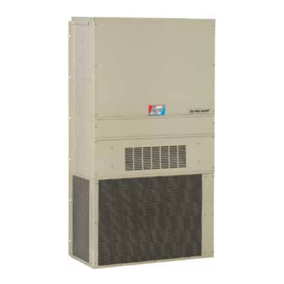
INSTALLATION INSTRUCTIONS WALL MOUNTING INFORMATION WARNING 1. Two holes for the supply and return air openings must be cut through the wall as shown in Figure 3. 2. On wood frame walls, the wall construction must be Failure to provide the 1/4 inch clearance strong and rigid enough to carry the weight of the between the supply duct and a combustible unit without transmitting any unit vibration.
FIGURE 4 ELECTRIC HEAT CLEARANCE W30H2, W36H2, W42H2, W48H2, W60H2 SIDE SECTION VIEW OF SUPPLY AIR DUCT FOR WALL MOUNTED UNIT SHOWING 1/4 INCH CLEARANCE TO COMBUSTIBLE SURFACES. WARNING A minimum of 1/4 inch clearance must be maintained between the supply air duct and combustible materials. This is required for the first 3 feet of ducting.
FIGURE 5 WALL MOUNTING INSTRUCTIONS WALL STRUCTURE SEE FIGURE 3 – MOUNTING INSTRUCTIONS FACTORY SUPPLIED RAIN FLASHING. MOUNT ON UNIT BEFORE INSTALLATION SUPPLY AIR SUPPLY AIR SUPPLY AIR DUCT OPENING OPENING RETURN AIR RETURN AIR RETURN AIR OPENING OPENING OPENING BOTTOM MOUNTING WOOD OR STEEL SIDING BRACKET.
FIGURE 7 COMMON WALL MOUNTING INSTALLATIONS SUPPLY DUCT MAY BE LOCATED IN AN ATTIC OR BELOW CEILING RAFTERS AS SHOWN RAIN RAIN FLASHING RAFTERS FLASHING RAFTERS FINISHED CEILING SURFACE SUPPLY AIR DUCT SUPPLY AIR DUCT FINISHED CEILING SURFACE W/ GRILLE RETURN AIR RETURN AIR OPENING W/ GRILLE...
WIRING – MAIN POWER WIRING – LOW VOLTAGE WIRING Refer to the unit rating plate for wire sizing information 230/208V, 1 phase and 3 phase equipment dual primary and maximum fuse or “HACR” type circuit breaker voltage transformers. All equipment leaves the factory wired on 240V tap.
7. Never fill cylinders over 80% of total capacity. TOPPING OFF SYSTEM CHARGE 8. Store cylinders in a cool area, out of direct If a leak has occurred in the system, Bard sunlight. Manufacturing recommends reclaiming, evacuating (see criteria above), and charging to the nameplate 9.
START UP (Continued) IMPORTANT INSTALLER NOTE PHASE MONITOR For improved start up performance wash the indoor coil All units with three phase scroll compressors are with a dish washing detergent. equipped with a 3 phase line monitor to prevent compressor damage due to phase reversal. HIGH &...
SEQUENCE OF OPERATION wire from the 60-minute terminal and reconnect to the desired COOLING – Circuit R-Y makes at thermostat pulling in terminal. Refer to Figure 8. There is a cycle speed up jumper on the control. This can be compressor contactor, starting the compressor and outdoor used for testing purposes to reduce the time between defrost motor.
TROUBLESHOOTING SOLID STATE HEAT PUMP CONTROL NOTE: If there was no power to 24 volt transformer, TROUBLESHOOTING PROCEDURE the compressor and outdoor fan motor will 1. NOTE: A thorough understanding of the defrost not start for 5 minutes. This is because of cycle sequence is essential.
CHECKING TEMPERATURE SENSOR 3. Check resistance reading to chart of resistance. Use OUTSIDE UNIT CIRCUIT sensor ambient temperature. (Tolerance of part is ± 10%.) 1. Disconnect temperature sensor from board and 4. If sensor resistance reads very low, then sensor is from outdoor coil.
MODEL (INCHES) evaluating proper system performance. They shall not W18H2 be used to adjust charge. If charge is in doubt, reclaim, 1.00" W24H2 evacuate and recharge the unit to the serial plate charge.
105° 110° 115° 120° TEMP. 75 DB Low Side 62 WB High Side 80 DB Low Side W18H2 67 WB High Side 85 DB Low Side 72 WB High Side 75 DB Low Side 62 WB High Side 80 DB...
Wire Ampacity Ckt. A Ckt. B Ckt. A Ckt. B Ckt. A Ckt. B Ckt. A Ckt. B Ckt. Brkr. Size W18H2-A00, A0Z 230/208-1 W24H2-A00, A0Z 230/208-1 1 or 2 W24H2-B00, B0Z 230/208-3 W24H2-C00, C0Z 460-3 W30H2-A00, A0Z* A05* 230/208-1...
TABLE 4B Electrical Specifications — Dehumidification Models Single Circuit Dual Circuit Minimum Maximum Rated Field Maximum Field Circuit External Fuse Field Power Ground MODEL Volts & Minimum Power External Power Ground Ampacity or Ckt.
TABLES 7 MAXIMUM ESP OF OPERATION ELECTRIC HEAT ONLY Model Front Outlet Top Outlet Model High High W18H Speed Speed Speed Speed W24H W30H W24H W36H W24H W30H W36H W30H W36H W42H W48H W60H Model Speed KW High Speed Low Speed High Speed Low Speed High Speed Low Speed -A00 -A04 -----...