Table of Contents
Advertisement
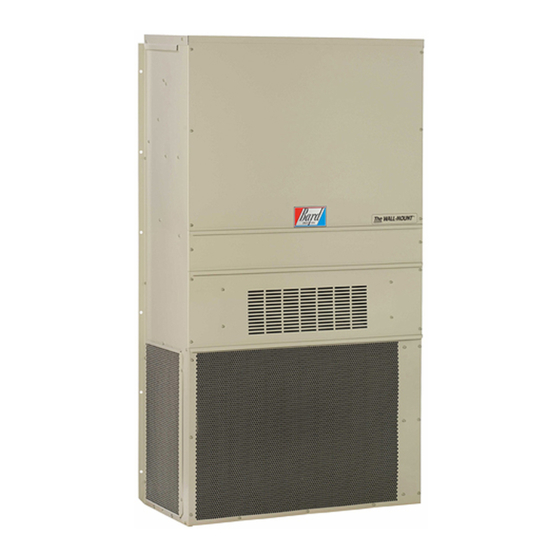
INSTALLATION INSTRUCTIONS
WALL MOUNTED PACKAGE
W18H2-A
W24H2-A
W24H2-B
W24H2-C
W30H2-A
W30H2-B
W30H2-C
W36H2-A
W36H2-B
W36H2-C
HEAT PUMP
Models:
W42H2-A
W42H2-B
W42H2-C
W48H2-A
W48H2-B
W48H2-C
W60H2-A
W60H2-B
W60H2-C
Bard Manufacturing Company, Inc.
Bryan, Ohio 43506
www.bardhvac.com
W24H2DA
W42H2DA
W24H2DB
W42H2DB
W24H2DC
W42H2DC
W30H2DA
W48H2DA
W30H2DB
W48H2DB
W30H2DC
W48H2DC
W36H2DA
W60H2DA
W36H2DB
W60H2DB
W36H2DC
W60H2DC
Manual:
Supersedes: 2100-604
Date:
Page
2100-604A
2-1-16
1 of 28
Advertisement
Table of Contents

Subscribe to Our Youtube Channel
Related Manuals for Bard W18H2-A


Summary of Contents for Bard W18H2-A
-
Page 1: Installation Instructions
W30H2DA W48H2DA W30H2-B W48H2-B W30H2DB W48H2DB W30H2-C W48H2-C W30H2DC W48H2DC W36H2-A W60H2-A W36H2DA W60H2DA W36H2-B W60H2-B W36H2DB W60H2DB W36H2-C W60H2-C W36H2DC W60H2DC Bard Manufacturing Company, Inc. Manual: 2100-604A Bryan, Ohio 43506 Supersedes: 2100-604 Date: 2-1-16 www.bardhvac.com Page 1 of 28... -
Page 2: Table Of Contents
CONTENTS Getting Other Information and Publications Start Up ..............15 General ............15 Wall Mount General Information ......4 Topping Off System Charge ......... 15 Wall Mount Model Nomenclature ......4 Safety Practices ..........15 Shipping Damage ..........4 Important Installer Note ........16 General .............. -
Page 3: Getting Other Information And Publications
GETTING OTHER INFORMATION AND PUBLICATIONS These publications can help when installing the For more information, contact these publishers: furnace. They can usually be found at the local library or purchased directly from the publisher. Be sure to ACCA Air Conditioning Contractors of America consult the current edition of each standard. -
Page 4: Wall Mount General Information
WALL MOUNT GENERAL INFORMATION HEAT PUMP WALL MOUNT MODEL NOMENCLATURE – CONTROL MODULES REVISIONS MODEL NUMBER (See Spec. Sheet S3398) CAPACITY 18 - 1½ Ton COIL OPTIONS VOLTS & PHASE H - Heat Pump 24 - 2 Ton A - 230/208/60/1 COLOR OPTIONS X - Standard 30 - 2½... -
Page 5: Duct Work
Any grille that meets with 5/8" louver criteria may be a drain system of some type, it must be an open or used. It is recommended that Bard Return Air Grille vented type system to assure proper drainage. Kit RG-2W through RG-5W or RFG-2W through RFG- 5W be installed when no return duct is used. -
Page 6: Installation
INSTALLATION WALL MOUNTING INFORMATION WARNING 1. Two holes for the supply and return air openings must be cut through the wall as shown in Figure 3. 2. On wood frame walls, the wall construction must Failure to provide the 1/4" clearance between be strong and rigid enough to carry the weight of the supply duct and a combustible surface the unit without transmitting any unit vibration. -
Page 7: Figure 2 Unit Dimensions
FIGURE 2 Dimensions of Basic Unit for Architectural and Installation Requirements (Nominal) Supply Return Width Depth Height Model W18H2 33.300 17.125 70.563 7.88 19.88 11.88 19.88 35.00 18.50 25.75 20.56 26.75 28.06 29.25 27.00 2.63 34.13 22.06 10.55 5.00 12.00 5.00 W24H2 W30H2 38.200 17.125 70.563 7.88 27.88 13.88 27.88 40.00 18.50 25.75 17.93 26.75 28.75 29.25 27.00 2.63 39.13 22.75 9.14 5.00 12.00 5.00... -
Page 8: Figure 3A Mounting Instructions W18, W24
Manual 2100-604A Page 8 of 28... -
Page 9: Figure 3B Mounting Instructions W30, W36
Manual 2100-604A Page 9 of 28... - Page 10 Manual 2100-604A Page 10 of 28...
-
Page 11: Figure 3C Mounting Instructions W42, W48, W60
FIGURE 4 Electric Heat Clearance W30H2, W36H2, W42H2, W48H2, W60H2 SIDE SECTION VIEW OF SUPPLY AIR DUCT FOR WALL MOUNTED UNIT SHOWING 1/4" CLEARANCE TO COMBUSTIBLE SURFACES. WARNING A minimum of 1/4" clearance must be maintained between the supply air duct and combustible materials. This is required for the first 3ʹ... -
Page 12: Figure 5 Wall Mounting Instructions
FIGURE 5 Wall Mounting Instructions WALL STRUCTURE SEE FIGURE 3 – MOUNTING INSTRUCTIONS FACTORY SUPPLIED RAIN FLASHING. MOUNT ON UNIT BEFORE INSTALLATION SUPPLY AIR SUPPLY AIR SUPPLY AIR DUCT OPENING OPENING RETURN AIR RETURN AIR RETURN AIR OPENING OPENING OPENING BOTTOM MOUNTING WOOD OR STEEL SIDING BRACKET. -
Page 13: Figure 7 Common Wall Mounting Installations
FIGURE 7 Common Wall Mounting Installations SUPPLY DUCT MAY BE LOCATED IN AN ATTIC OR BELOW CEILING RAFTERS AS SHOWN RAIN RAIN FLASHING RAFTERS FLASHING RAFTERS FINISHED CEILING SURFACE SUPPLY AIR DUCT SUPPLY AIR DUCT FINISHED CEILING SURFACE W/ GRILLE RETURN AIR RETURN AIR OPENING W/ GRILLE... -
Page 14: Wiring - Main Power
WIRING – LOW VOLTAGE WIRING WIRING – MAIN POWER Refer to the unit rating plate for wire sizing information All 230/208V 1 phase and 3 phase equipment have All equipment and maximum fuse or circuit breaker size. Each dual primary voltage transformers. outdoor unit is marked with a “Minimum Circuit leaves the factory wired on 240V tap. -
Page 15: Start Up
7. Never fill cylinders over 80% of total capacity. TOPPING OFF SYSTEM CHARGE 8. Store cylinders in a cool area, out of direct If a leak has occurred in the system, Bard sunlight. Manufacturing recommends reclaiming, evacuating 9. Never heat cylinders above 125°F. -
Page 16: Important Installer Note
IMPORTANT INSTALLER NOTE PHASE MONITOR For improved start up performance, wash the indoor All units with three phase scroll compressors are coil with a dishwashing detergent. equipped with a three phase line monitor to prevent compressor damage due to phase reversal. HIGH AND LOW PRESSURE SWITCH The phase monitor in this unit is equipped with two LEDs. -
Page 17: Sequence Of Operation
SEQUENCE OF OPERATION When the temperature rises to approximately 57°F, the coil temperature sensor will send a signal to the heat COOLING – Circuit R-Y makes at thermostat pulling pump control which will return the system to heating in compressor contactor, starting the compressor operations automatically. -
Page 18: Figure 8 Defrost Control Board
Pressure will rise fairly fast as there is likely no actual After this period expires, the control will then monitor frost on the outdoor coil in this artificial test condition. the low pressure switch input normally to make sure that the switch is closed during “Y” operation. There is also a 5-minute compressor time delay function built into the HPC. -
Page 19: Service
SERVICE SOLID STATE HEAT PUMP CONTROL 4. Set system switch to “heat” or “cool”. Adjust TROUBLESHOOTING PROCEDURE thermostat to call for heat or cool. The indoor blower, compressor and outdoor fan should start. 1. NOTE: A thorough understanding of the defrost cycle sequence is essential. -
Page 20: Checking Temperature Sensor
CHECKING TEMPERATURE SENSOR 3. Check resistance reading to chart of resistance. Use sensor ambient temperature. (Tolerance of OUTSIDE UNIT CIRCUIT part is ± 10%.) 1. Disconnect temperature sensor from board and 4. If sensor resistance reads very low, then sensor is from outdoor coil. -
Page 21: Figure 9 Fan Blade Setting
FAN BLADE SETTING DIMENSIONS REMOVAL OF FAN SHROUD The correct fan blade setting for proper air delivery 1. Disconnect all power to the unit. across the outdoor coil is shown in Figure 9. Refer to 2. Remove the screws holding both grilles, one on Table 2 for unit specific dimension. -
Page 22: Table 3A Cooling Pressure
TABLE 3A – Cooling Pressure Table RETURN AIR TEMPERATURE ENTERING OUTDOOR COIL MODEL PRESSURE 75° 80° 85° 90° 95° 100° 105° 110° 115° 120° TEMP. 75 DB Low Side 62 WB High Side 80 DB Low Side W18H2 67 WB High Side 85 DB Low Side... -
Page 23: Table 4A Electrical Specifications
TABLE 4A Electrical Specifications Single Circuit Dual Circuit Minimum Maximum Rated Volts Field Maximum Field Circuit External Fuse or Field Power Ground MODEL Minimum & Phase Power External Power Ground Ampacity Ckt. Breaker Wire Size Wire Size Circuit Circuits Fuse or... -
Page 24: Table 4B Electrical Specifications
TABLE 4B Electrical Specifications — Dehumidification Models Single Circuit Dual Circuit Minimum Maximum Rated Volts Field Maximum Field Circuit External Fuse or Field Power Ground MODEL Minimum & Phase Power External Power Ground Ampacity Ckt. -
Page 25: Table 5 Recommended Airflow
TABLE 5 Recommended Airflow Recommended Factory Speed Model Rated CFM * Rated ESP * Airflow Range Connection W18H 575 - 725 High 600 W24H 700 - 950 High W30H 1000 930 - 1300 High W36H 1100 930 - 1350 High W42H 1400... -
Page 26: Tables 7 Maximum Esp Electric Heat Only
TABLES 7 Maximum ESP of Operation Electric Heat Only Model Front Outlet Top Outlet Model High High W18H Speed Speed Speed Speed W24H W30H W24H W36H W24H W30H W36H W30H W36H W42H W48H W60H Model Speed KW High Speed Low Speed High Speed Low Speed High Speed... -
Page 27: Table 9 Optional Accessories
TABLE 9 Optional Accessories Part Number EHWH02A-A04 EHWH02A-A08 EHW24H-A04 EHW24H-A08 EHW24H-B06 EHWH30-A05 EHWH30-A10 EHWH36-A05 EHWH36-A10 EHWH36-A15 EHWH03-B06 EHW36H-B06 EHWH03-B09 EHW30H-B15 EHWC03A-C06 EHWH42-A05 EHWH42-A10 EHWH42-A15 EHWH-04-A20 EHWH05-B06 EHWH05-B09 EHWH05-B15 EHWH42-C06 EHWH05A-C09 EHWH05A-C15 EHWH04-A15 EHWH04-A10 EHW05H-B18 WMCB-02A WMCB-02B WMCB-03A WMCB-03B WMCB-06A WMCB-05B WMCB-07B WMCB-08A WMCB-09A... -
Page 28: Table 10 Vent And Control Options
TABLE 10 Vent and Control Options Part Number Description CMC-14 CMC-15 Start Kit (230V 1-Phase only) SK111 Start Kit (230V 1-Phase only) CMC-28 BFAD-2 Barometric Fresh Air Damper - Standard BOP-2 Blank Off Plate MFAD-2 Motorized Fresh Air Damper CRV-2 Commercial Ventilator - Spring Return ECONWMS-E2B...
Need help?
Do you have a question about the W18H2-A and is the answer not in the manual?
Questions and answers