Table of Contents
Advertisement
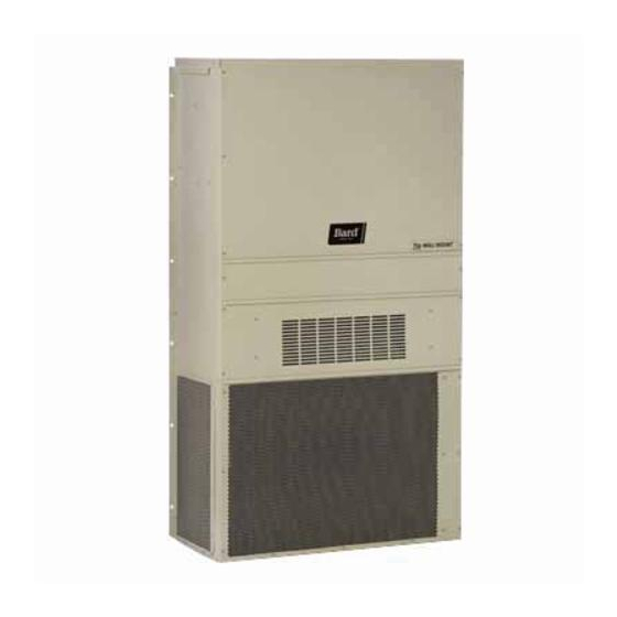
INSTALLATION INSTRUCTIONS
WALL MOUNTED PACKAGE
W18HB-A
Bard Manufacturing Company, Inc.
Bryan, Ohio 43506
www.bardhvac.com
HEAT PUMP
Models:
W24HB-A
W24HB-B
W24HB-C
W30HB-A
W30HB-B
W30HB-C
W36HB-A
W36HB-B
W36HB-C
W24HBDA
W24HBDB
W24HBDC
W30HBDA
W30HBDB
W30HBDC
W36HBDA
W36HBDB
W36HBDC
Manual:
2100-703
Supersedes: NEW
Date:
8-12-19
Page
1 of 40
Advertisement
Table of Contents
Troubleshooting

Subscribe to Our Youtube Channel
Related Manuals for Bard W18HB-A


Summary of Contents for Bard W18HB-A
-
Page 1: Installation Instructions
HEAT PUMP Models: W18HB-A W24HB-A W24HBDA W24HB-B W24HBDB W24HB-C W24HBDC W30HB-A W30HBDA W30HB-B W30HBDB W30HB-C W30HBDC W36HB-A W36HBDA W36HB-B W36HBDB W36HB-C W36HBDC Bard Manufacturing Company, Inc. Manual: 2100-703 Supersedes: NEW Bryan, Ohio 43506 Date: 8-12-19 www.bardhvac.com Page 1 of 40... -
Page 2: Table Of Contents
CONTENTS Getting Other Information and Publications ..3 Service ..............25 Wall Mount General Information ......4 Solid State Heat Pump Control Troubleshooting Heat Pump Wall Mount Model Nomenclature ..4 Procedure ............25 Shipping Damage ..........4 Checking Temperature Sensor Outside General ............... -
Page 3: Getting Other Information And Publications
FIGURES GRAPHS Figure 1 Fresh Air Damper ........5 Graph 1 W18HB FAD-NE2, 3 W/O Exhaust Figure 2 Unit Dimensions ........9 Ventilation Delivery ......39 Figure 3A Mounting Instructions – W18H, W24H .. 10 Graph 2 W24HB FAD-NE2, 3 W/O Exhaust Figure 3B Mounting Instructions –... -
Page 4: Wall Mount General Information
WALL MOUNT GENERAL INFORMATION HEAT PUMP WALL MOUNT MODEL NOMENCLATURE – CONTROL MODULES REVISIONS MODEL NUMBER (See Spec. Sheet S3585) CAPACITY 18 - 1½ Ton VOLTS & PHASE COIL OPTIONS H - Heat Pump 24 - 2 Ton A - 230/208/60/1 X - Standard COLOR &... -
Page 5: Filters
Any grille that meets with 5/8" louver criteria may be in place and is recommended for maximum energy efficiency. used. It is recommended that Bard Return Air Grille Kit RG-2W through RG-5W or RFG-2W through RFG- The blank-off plate is available upon request from the 5W be installed when no return duct is used. -
Page 6: Installation
INSTALLATION Basic Installation Design and contact with the base of the unit. If allowed, this could cause damage to the coil and other Application Planning base components. Also, be sure there are no Successful unit installations require proper planning air obstructions to the sides or front of the and site inspection before installation begins. -
Page 7: Ducted Applications
5/8". It is recommended that a Maximum External Static Pressure (ESP) of Operation Bard Return Air Grille Kit be installed that is designed Table 17 on page 36. Design the duct work according specifically for the wall mount product. Contact the to methods given by the Air Conditioning Contractors local Bard distributor or visit www.bardhvac.com for... -
Page 8: Unit Installation
Unit Installation flashing is supplied for field use and is mounted to the back of the unit for shipping. Remove rain Make sure to have the proper tools at the work site that flashing before locating the unit against wall. Top are needed for unit installation. -
Page 9: Table 1 Clearance Required For Service Access And Adequate Condenser Airflow
2. Field ventilation installation with the unit installed requires 40" on the left or right side of the unit. 3. Bard recommends a minimum of 10' between the unit front condenser air outlet and solid objects including fences, walls, bushes and other airflow obstructions. -
Page 10: Figure 3A Mounting Instructions - W18H, W24H
Manual 2100-703 Page 10 of 40... -
Page 11: Figure 3B Mounting Instructions - W30H, W36H
Manual 2100-703 Page 11 of 40... -
Page 12: Figure 4 Electric Heat Clearance
FIGURE 4 Electric Heat Clearance W30H and W36H SIDE SECTION VIEW OF SUPPLY AIR DUCT FOR WALL-MOUNTED UNIT SHOWING 1/4" CLEARANCE TO COMBUSTIBLE SURFACES. WARNING Fire hazard. Maintain minimum 1/4" clearance between the supply air duct and combustible materials in the first 3' of ducting. -
Page 13: Figure 5 Wall Mounting Instructions
FIGURE 5 Wall Mounting Instructions WALL STRUCTURE SEE FIGURES 3A-B – MOUNTING INSTRUCTIONS FACTORY SUPPLIED RAIN FLASHING. MOUNT ON UNIT BEFORE INSTALLATION SUPPLY AIR SUPPLY AIR SUPPLY AIR DUCT OPENING OPENING RETURN AIR RETURN AIR RETURN AIR OPENING OPENING OPENING BOTTOM MOUNTING WOOD OR STEEL SIDING BRACKET. -
Page 14: Figure 7 Common Wall Mounting Installations
FIGURE 7 Common Wall Mounting Installations SUPPLY DUCT MAY BE LOCATED IN AN ATTIC OR BELOW CEILING RAFTERS AS SHOWN RAIN RAIN FLASHING RAFTERS FLASHING RAFTERS FINISHED CEILING SURFACE SUPPLY AIR DUCT SUPPLY AIR DUCT FINISHED CEILING SURFACE W/ GRILLE RETURN AIR RETURN AIR OPENING W/ GRILLE... -
Page 15: Wiring - Main Power
Wiring – Main Power Low Voltage Connections These units use a 24-volt AC low voltage circuit. Refer to the unit rating plate for wire sizing information and maximum fuse or circuit breaker size. Each C terminal is 24VAC common and is grounded. outdoor unit is marked with a “Minimum Circuit G terminal is the indoor blower input. -
Page 16: Dehumidification Feature
TABLE 3 Units with an economizer will not have the brass jumper installed. Refer to vent manuals for instructions on how Low Voltage Connections Balanced Climate works with each vent. Units w/ To operate in Balanced Climate mode, a 2-stage cooling Standard Units Economizers thermostat is required. -
Page 17: Table 4 Wall Thermostats
TABLE 4 Wall Thermostats Part Number Predominate Features 8403-057 1 stage Cool, 1 stage Heat; Electronic Non-Programmable; Auto or Manual changeover (TH3110D1040) 8403-059 2 stage Cool, 2 stage Heat; Electronic Non-Programmable; HP or Conventional (Default: AC); Auto or Manual (TH5220D1219/U) changeover 8403-060 3 stage Cool;... - Page 18 Programmable Thermostat Connections Completestat Model #CS9B-THO or Model #CS9BE-THO W1/E Thermostat W1/E YO/D Bard #8403-060 Optional CO2 Controller Bard Part #8403-067 24VAC CO2 OUT TEMP-OUT Unit Low B/W1 Voltage Term. Strip 12-Pin Vent Plug ALL VENT OPTIONS PLUG IN HERE If not equipped with a ventilation option to plug in, a jumper plug must be installed.
-
Page 19: Figure 9 Non-Programmable Thermostat Connections
(TH311OD1040) or T4 Pro 8403-089 8403-058 (TH522OD1151) 8403-047 8403-059 (TH522OD1219/U) Electronic Humidistat or T6 Pro 8403-090 Optional CO2 Controller Bard Part #8403-067 24VAC CO2 OUT TEMP-OUT Unit Low B/W1 Voltage Term. Strip 12-Pin Vent Plug ALL VENT OPTIONS PLUG IN HERE If not equipped with a ventilation option to plug in, a jumper plug must be installed. -
Page 20: Start Up
Topping Off System Charge 10. Never trap liquid R-410A in manifold sets, gauge lines or cylinders. R-410A expands significantly If a leak has occurred in the system, Bard at warmer temperatures. Once a cylinder or line is Manufacturing recommends reclaiming, evacuating... -
Page 21: High And Low Pressure Switch
The phase monitor in this unit is equipped with two If the Bard air conditioning system is being set up LEDs. If the Y signal is present at the phase monitor in a typical environment where 72°F is the lowest and phases are correct, the green LED will light. -
Page 22: Defrost Cycle
1/4" QC, to short between the SPEEDUP If the unit is being installed with any ventilation terminals to accelerate the HPC timer and initiate package, a Bard LAC kit must be installed. Failure to defrost. utilize an LAC with any air conditioner can cause coil Be careful not to touch any other terminals with the freeze up. -
Page 23: High Pressure Switch Operation
Service Hints After this period expires, the control will then monitor the low pressure switch input normally to make sure 1. Caution owner/operator to maintain clean air that the switch is closed during “Y” operation. filters at all times and to not needlessly close off High Pressure Switch Operation supply and return air registers. -
Page 24: Figure 10 Defrost Control Board
FIGURE 10 Defrost Control Board TIME (SEC) LOW PRESSURE BYPASS TIMER SWITCH 120* *(FACTORY SETTING 120 SECONDS) ACCUMULATED DEFROST TIME TIMER (FACTORY SETTING 60 MIN.) MIS-2668 A Model Setting W18HB W24HB W30HB W36HB Manual 2100-703 Page 24 of 40... -
Page 25: Service
SERVICE Solid State Heat Pump Control NOTE: If there was no power to 24 volt transformer, Troubleshooting Procedure the compressor and outdoor fan motor will not start for 5 minutes. This is because of the 1. NOTE: A thorough understanding of the defrost compressor short cycle protection. -
Page 26: Checking Temperature Sensor Outside Unit Circuit
Checking Temperature Sensor Outside 3. Check resistance reading to chart of resistance. Use sensor ambient temperature. (Tolerance of part Unit Circuit is ± 10%.) 1. Disconnect temperature sensor from board and 4. If sensor resistance reads very low, sensor is from outdoor coil. -
Page 27: Troubleshooting Nidec Selectech Series Ecm Motors
“Continuous Fan” only problem identified. on the “G” terminal. NOTE: Bard Models PA13242; PA13302; PA13362-A, -B; PA13422-A, -B, -C; PA13482-A, -B, -C; PA13602-A, -B, -C 2. If the system is excessively noisy, does not appear contain the X13-Series Motors. -
Page 28: Model Selectech Communication Diagnostics
TROUBLESHOOTING GE X13-SERIES ECM2.3 ™ MOTORS CONT’D. Model SelecTech Communication Diagnostics B. If the motor has proper high voltage as identified above (If the Motor Is Not Running 2. Initiate a demand from the thermostat and check the The SelecTech motor is communicated through 24 VAC Model X13 Communication Diagnostics #1 on page 27), proper low voltage to a voltage between the common and the appropriate motor... -
Page 29: Fan Blade Setting Dimensions
Fan Blade Setting Dimensions Removal of Fan Shroud The correct fan blade setting for proper air delivery 1. Disconnect all power to the unit. across the outdoor coil is shown in Figure 13. Refer to 2. Remove the screws holding both grilles, one on Table 10 for unit specific dimension. -
Page 30: Table 11A Cooling Pressure
TABLE 11A Cooling Pressure Air Temperature Entering Outdoor Coil °F Return Air Temp Model Pressure (DB/WB) Low Side 75/62 High Side Low Side W18HB 80/67 High Side Low Side 85/72 High Side Low Side 75/62 High Side Low Side W24HB 80/67 High Side Low Side... -
Page 31: Table 12 Cooling Pressure - Balanced Climate Airflow
TABLE 12 Cooling Pressure – Balanced Climate Airflow Air Temperature Entering Outdoor Coil °F Return Air Temp Model Pressure (DB/WB) Low Side 75/62 High Side Low Side W18HB 80/67 High Side Low Side 85/72 High Side Low Side 75/62 High Side Low Side W24HB 80/67... -
Page 32: Table 13 Electrical Specifications
TABLE 13 Electrical Specifications Single Circuit Dual Circuit Minimum Maximum Rated Volts Field Maximum Field Circuit External Fuse Field Power Ground Model Minimum & Phase Power External Power Ground Ampacity or Ckt. Breaker Wire Size Wire Size Circuit Circuits Fuse or... -
Page 33: Setting Unit Airflow
24VAC signals from the low voltage terminal block located inside the control panel by a thermostat or other controlling device. Each speed tap is programmed by Bard at the factory to different motor torque settings (see Figure 14). Manual... -
Page 34: Speed Tap 1 - Vent/Blower Only
Speed Tap 1 – Vent/Blower Only the jumper between Y1 and Y2 installed and it must be removed to use Balanced Climate mode. The unit Speed taps 1 and 3 are programmed to identical is shipped with the orange/black wire connected to torque settings in the ECM motor. -
Page 35: Table 16 Indoor Blower Performance
TABLE 16 Indoor Blower Performance Default LO Optional MED Balanced Climate Optional HI Cooling Cooling & Heating/ Cooling & Heating E.S.P. Speed & Heating Speed Ventilation Speed Speed (In. H Dry Coil Wet Coil Dry Coil Wet Coil Dry Coil Wet Coil Dry Coil Wet Coil... -
Page 36: Electric Heat Only
TABLE 17 Maximum ESP of Operation Electric Heat Only Model Front Outlet Model A00/0Z High W18H Speed Speed W24H A00/0Z B00/0Z W30H W24H W36H C00/0Z W24H B00/0Z W30H W36H C00/0Z W30H W36H TABLE 18 Electric Heat Models 240V-1 208V-1 240V-3 208V-3 460V-3 Amps... -
Page 37: Table 19 Optional Accessories
TABLE 19 Optional Accessories Part Number EHW18H-A04 EHW18H-A08 EHW2TH-A04 EHW2TH-A08 EHWH24-B06B EHWH24B-C06 EHWH30-A05 EHW30H-A10 EHWH36-A05 Heater Kits EHW3TH-A10 EHW3TH-A15 EHWH03-B06 EHW36H-B06 EHWH03-B09 EHW3TH-B15 EHW3TH-C06 EHW3TA-C09 EHW3TH-C15 WMCB-02A WMCB-02B Circuit Breaker (WMCB) WMCB-03A & WMCB-03B Pull Disconnect (WMPD) WMCB-06A WMPD-01C Manual 2100-703 Page 37 of 40... -
Page 38: Table 20 Vent And Control Options
TABLE 20 Vent and Control Options Part Number Description CMC-15 Start Relay (PTCR based) CMC-31 Dirty Filter Sensor Kit CMC-34 Alarm Relay Crankcase Heater – 230V CMC-36 CMC-37 Crankcase Heater – 460V CMH-28 Outdoor Thermostat – Heat Pump (ODT) CMH-33 Low Ambient Control Modulating –... - Page 39 GRAPH 1 W18HB FAD-NE2, 3 W/O Exhaust Ventilation Delivery GRAPH 2 W24HB FAD-NE2, 3 W/O Exhaust Ventilation Delivery Manual 2100-703 Page 39 of 40...
- Page 40 GRAPH 3 W30HB FAD-NE2, 3 W/O Exhaust Ventilation Delivery GRAPH 4 W36HB FAD-NE2, 3 W/O Exhaust Ventilation Delivery Manual 2100-703 Page 40 of 40...
Need help?
Do you have a question about the W18HB-A and is the answer not in the manual?
Questions and answers