
Related Manuals for King Industrial KC-26FXT/i50/5052


Summary of Contents for King Industrial KC-26FXT/i50/5052
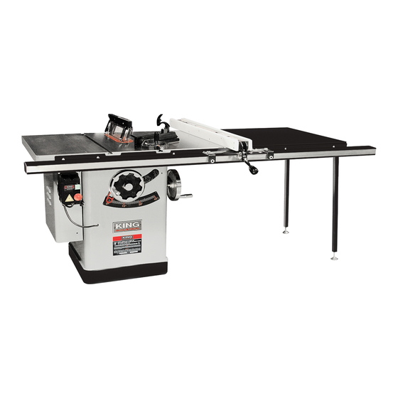
- Page 1 10” EXTREME CABINET TABLE SAWS WITH RIVING KNIFE MODEL: KC-26FXT/i50/5052 (50” Max Rip) Left Tilt MODEL: KC-26FXT/i30/30 (30” Max Rip) INSTRUCTION MANUAL COPYRIGHT © 2010 ALL RIGHTS RESERVED BY KING CANADA TOOLS INC.
-
Page 2: Warranty Information
WARRANTY INFORMATION 2-YEAR KING CANADA TOOLS LIMITED WARRANTY OFFERS A 2-YEAR LIMITED WARRANTY FOR THIS 10” CABINET SAW FOR INDUSTRIAL USE. PROOF OF PURCHASE Please keep your dated proof of purchase for warranty and servicing purposes. REPLACEMENT PARTS Replacement parts for this product are available at our authorized King Canada service centers across Canada. LIMITED TOOL WARRANTY King Canada makes every effort to ensure that this product meets high quality and durability standards. -
Page 3: General Safety Instructions For Power Tools
GENERAL SAFETY INSTRUCTIONS FOR POWER TOOLS 1. KNOW YOUR TOOL watch) because they could get caught in moving parts. Non-slip Read and understand the owners manual and labels affixed to footwear is recommended. Wear protective hair covering to the tool. Learn its application and limitations as well as its contain long hair. -
Page 4: Specifications Chart
AND SPECIFICATIONS 1. 4” Dust chute attached to removable panel 10. Slide tube 2. Emergency stop button 11. Support legs with adjustable feet (KC-26FXT/i50/5052 only) 3. Magnetic switch (thermal protection) 12. Motor access door 4. Table insert 13. Blade raising handwheel 5. - Page 5 ELECTRICAL REQUIREMENTS & MAGNETIC SWITCH OPERATION WARNING! ALL ELECTRICAL CONNECTIONS MUST BE DONE BY A QUALIFIED ELECTRICIAN. FAILURE TO COMPLY MAY RESULT IN SERIOUS INJURY! ALL ADJUSTMENTS OR REPAIRS MUST BE DONE WITH THE MACHINE DISCONNECTED FROM THE POWER SOURCE. FAILURE TO COMPLY MAY RESULT IN SERIOUS INJURY! PROPERLY POWER SUPPLY GROUNDED OUTLET...
- Page 6 ASSEMBLY DISASSEMBLING MOTOR BRACKET For shipping purposes, a motor bracket (A) Fig.4 is bolted to the cabinet and attached to the motor mount. This motor bracket must be removed before assembling, adjusting or operating this cabinet saw. You should keep this motor bracket in case you plan on shipping your cabinet saw.
- Page 7 INSTALLING SUPPORT LEGS FOR LAMINATED EXTENSION TABLE (KC-26FXT/I50/5052 ONLY) Fasten the 2 support legs to the inner edge of the laminated extension table using 4 hex. bolts, 8 washers, 4 spring washers and 4 hex. nuts. Refer to the parts diagram for assembly.
-
Page 8: Installing / Changing Blade
ASSEMBLY INSTALLING / CHANGING BLADE 1. Make sure the cabinet saw is Off and the power cord is disconnected. 2. If you are replacing a blade, raise the saw blade to its maximum height and lock the saw at 0 degrees. Remove the table insert. 3. -
Page 9: Blade Raising And Tilting Mechanism
ADJUSTMENTS POSITIONING AND ADJUSTING MITER GAUGE The miter gauge shown in Fig.15 normally gets positioned on the left side of the blade by sliding the miter gauge bar (A) into the table T-slot. It is important to make sure there is no side to side play, to adjust, loosen cap screws which hold adjust guide blocks (B), tighten the set screws mounted in the adjust guide blocks, retighten the 2 cap screws and test the adjustment, adjust as necessary. -
Page 10: Aligning Table T-Slot Parallel With Blade
ADJUSTMENTS ALIGNING TABLE T-SLOT PARALLEL WITH BLADE The table T-slot must be aligned parallel with the blade. Using a combination square (A) Fig.20, measure the distance from the back edge of the blade to the table T-slot. Pivot blade forward 180º and remeasure the distance using the exact same point on the blade. -
Page 11: Adjusting 45 And 90 Degree Positive Stops
ADJUSTMENTS & OPERATION ADJUSTING 45 AND 90 DEGREE POSITIVE STOPS The blade tilting mechanism of your saw is equipped with a positive stop at 45 and 90 degrees. To check and adjust these positive stops, proceed as follows: 1. Raise the saw blade to its maximum height. 2. -
Page 12: Operation
OPERATION RIPPING Ripping is the operation of making a lengthwise cut through a board, as shown in Fig.27, and the rip fence is used to position and guide the work. One edge of the work rides against the rip fence while the flat side of the board rest on the table. Since the work is pushed along the fence, it must have a straight edge and make solid contact with the table. -
Page 13: Maintenance & Optional Accessories
MAINTENANCE & OPTIONAL ACCESSORIES This table saw requires very little maintenance other than minor lubrication and cleaning. The following sections detail what will need to be done in order to assure continued operation of your saw. LUBRICATION The table saw has sealed lubricated bearings in the motor housing and the arbor assembly, they will not require any additional lubrication. -
Page 14: Troubleshooting
TROUBLESHOOTING PROBLEM SOLUTION SAW WILL NOT START 1. Saw not plugged in. 1. Plug in saw. 2. Fuse blown or circuit breaker tripped. 2. Replace fuse or reset circuit breaker. 3. Cord damaged. 3. Have cord replaced by a certified electrician. OVERLOAD KICKS OUT FREQUENTLY 1.
Need help?
Do you have a question about the KC-26FXT/i50/5052 and is the answer not in the manual?
Questions and answers