
Related Manuals for King Industrial KC-1402FX


Summary of Contents for King Industrial KC-1402FX
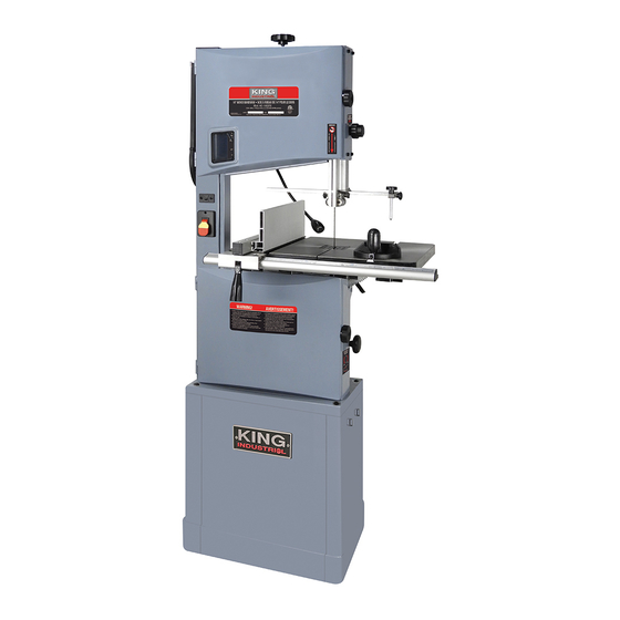
- Page 1 14” WOOD BANDSAW WITH STAND 05/2019 INSTRUCTION MANUAL MODEL: KC-1402FX COPYRIGHT © 2019 ALL RIGHTS RESERVED BY KING CANADA TOOLS INC.
-
Page 2: Warranty Information
WARRANTY INFORMATION 2-YEAR kINg CANADA TOOLS LIMITED WARRANTY OFFERS A 2-YEAR LIMITED WARRANTY FOR THIS 14” WOOD BANDSAW INTENDED FOR NON COMMERCIAL USE PROOF OF PURCHASE Please keep your dated proof of purchase for warranty and servicing purposes. REPLACEMENT PARTS Replacement parts for this product are available at our authorized King Canada service centres across Canada. -
Page 3: General Safety Rules
gENERAL SAFETY RULES 1. kNOW YOUR TOOL 12. ALWAYS WEAR SAFETY gLASSES. Read and understand the owners manual and labels affixed to Always wear safety glasses (ANSI Z87.1). Everyday eye-glasses only have impact resistant lenses, they are NOT the tool. Learn its application and limitations as well as its specific potential hazards. -
Page 4: Specific Safety Rules
SPECIFIC SAFETY RULES Safety is a combination of common sense, staying alert and • Use extra supports (tables, blocks, etc...) for any workpieces knowing how your bandsaw works. Read and understand the large enough to tip when not held down to the table top. following safety rules before operating. - Page 5 25. Dust chute. This feature helps eliminate sawdust from inside the machine. This dust chute accepts 2”, 3” and 4” dust collection hoses for optimal sawdust removal. Specifications MODEL kC-1402FX 14” Cutting capacity frame to blade Maximum depth of cut 8-3/4”...
-
Page 6: Electrical Information
ELECTRICAL INFORMATION WARNINg! ALL ELECTRICAL CONNECTIONS MUST BE DONE BY A QUALIFIED ELECTRICIAN. FAILURE TO COMPLY MAY RESULT IN SERIOUS INJURY! ALL ADJUSTMENTS OR REPAIRS MUST BE DONE WITH THE MACHINE DISCONNECTED FROM THE POWER SOURCE. FAILURE TO COMPLY MAY RESULT IN SERIOUS INJURY! POWER SUPPLY PROPERLY gROUNDED OUTLET WARNINg: YOUR BANDSAW MUST BE CONNECTED TO A 110V-120V,... -
Page 7: Installing The Table
ASSEMBLY WARNINg: To avoid injury, if any parts are missing, do not attempt to assemble the bandsaw, plug in the power cord, or turn the switch on, until the missing parts are obtained and installed correctly. WARNINg: For your own safety, never connect plug to power source outlet, or insert switch key until all assembly steps are complete and until you have read and understood the entire instruction manual. - Page 8 ASSEMBLY ALIgNINg FENCE RAIL 1) The left side “zero” mark on the ruler of the fence rail (A) Fig.8 must be aligned with the blade. Slide rip fence up against the blade, lock the fence by lowering the fence lock handle. 2) Reposition the fence rail (A) Fig.8 so the zero mark aligns with the indicator line (B) of the rip fence window (C).
-
Page 9: Operation & Adjustments
OPERATION & ADJUSTMENTS WARNINg! Turn off the saw, remove the main On/Off switch safety key and unplug the power cord before making any adjustments on the saw. ADJUSTINg TABLE 90 TO THE BLADE 1) The table stop (A) Fig.12 is set at the factory to stop the table at 90º (perpendicular) with the blade. -
Page 10: Adjusting Blade Tension
OPERATION & ADJUSTMENTS WARNINg! Turn off the saw, remove the main On/Off switch safety key and unplug the power cord before making any adjustments on the saw. ADJUSTINg BLADE TENSION The blade tension knob (A) Fig.16 is used to adjust blade tension. The quick release tension lever (A) Fig.15 must be engaged (moved to the left) before making blade tension adjustments with the blade tension knob. -
Page 11: Adjusting Upper Blade Guide Assembly
OPERATION & ADJUSTMENTS WARNINg! Turn off the saw, remove the main On/Off switch safety key and unplug the power cord before making any adjustments on the saw. CHANgINg SPEED (1476 OR 3280 SFPM)/ TENSIONINg BELT This Bandsaw is capable of two cutting speeds (1476 or 3280 SFPM). To change cutting speed: 1) Open lower blade cover. -
Page 12: Adjusting Lower Blade Guide Assembly
OPERATION & ADJUSTMENTS ADJUSTINg LOWER BLADE gUIDE ASSEMBLY After installing a different blade, it is necessary to adjust the upper and lower blade guide assemblies. To adjust lower blade guide assembly: 1) Disconnect machine from power source. 2) The lower blade guide housing (B) Fig.22 must be adjusted so that the blade rests between the guide bearings (D). -
Page 13: Operation And Maintenance
OPERATION & MAINTENANCE DUST COLLECTION This bandsaw comes with a versatile dust chute (A) Fig.26 which accepts 2”, 3” and 4” dust collection hoses. Note: Wood dust and chips in a confined area can give rise to fire or an explosion. keep ignition sources away from Bandsaw. keep saw dust to a minimum by cleaning the inside of the Bandsaw after every use. -
Page 14: Maintenance
MAINTENANCE MAINTENANCE Motor/Electrical Frequently vacuum or blow out any sawdust from the motor and around the switches. Lubrication All the ball bearings are permanently lubricated. They require no further lubrication. WARNINg! If the power cord is worn, cut or damaged in any way, replace it immediately. WARNINg! To prevent electrocution, fire or injury, use only identical replacement parts listed in this manual.
Need help?
Do you have a question about the KC-1402FX and is the answer not in the manual?
Questions and answers