
Related Manuals for King Industrial KC-1702FXB


Summary of Contents for King Industrial KC-1702FXB
-
Page 1: Instruction Manual
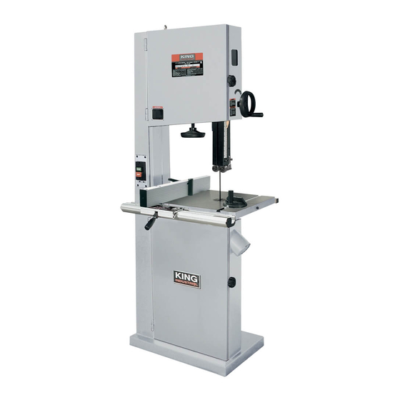
17” WOOD BANDSAW MODEL: KC-1702FXB INSTRUCTION MANUAL COPYRIGHT © 2010 ALL RIGHTS RESERVED BY KING CANADA TOOLS INC. -
Page 2: Warranty Information
WARRANTY INFORMATION & SPECIFICATIONS 2-YEAR KING CANADA TOOLS LIMITED WARRANTY OFFERS A 2-YEAR LIMITED WARRANTY FOR COMMERCIAL USE. FOR THIS 17” WOOD BANDSAW PROOF OF PURCHASE Please keep your dated proof of purchase for warranty and servicing purposes. REPLACEMENT PARTS Replacement parts for this product are available at our authorized King Canada service centers across Canada. -
Page 3: General Safety Instructions For Power Tools
GENERAL SAFETY INSTRUCTIONS FOR POWER TOOLS 1. KNOW YOUR TOOL 12. ALWAYS WEAR SAFETY GLASSES. Read and understand the owners manual and labels affixed to Always wear safety glasses (ANSI Z87.1). Everyday eyeglasses only have impact resistant lenses, they are NOT the tool. - Page 4 GETTING TO KNOW YOUR 17” WOOD BANDSAW FRONT OF BAND SAW UPPER DRIVE WHEEL UPPER WHEEL COVER HAND DRIVE BLADE TENSION ADJUSTMENT KNOB BLADE TENSION WINDOW UPPER BALL BEARING GUIDE SYSTEM SWITCH MITER SLOT TABLE RIP FENCE 4” DUST PORT LOWER WHEEL COVER POSITIVE KNOB...
-
Page 5: Electrical Connections
ELECTRICAL CONNECTIONS WARNING! ALL ELECTRICAL CONNECTIONS MUST BE DONE BY A QUALIFIED ELECTRICIAN. FAILURE TO COMPLY MAY RESULT IN SERIOUS INJURY! ALL ADJUSTMENTS OR REPAIRS MUST BE DONE WITH THE BANDSAW DISCONNECTED FROM THE POWER SOURCE. FAILURE TO COMPLY MAY RESULT IN SERIOUS INJURY! WARNING: YOUR BANDSAW MUST BE CONNECTED TO A 110- 110V EXTENSION CORDS 120V, 15-AMP, BRANCH CIRCUIT AND USE A 20-AMP TIME DELAY... -
Page 6: Adjusting 90 Degree Table Stop
ASSEMBLY & OPERATIONS MOVING YOUR BANDSAW 1. Use a 2000kg. chain hoist connected to the top mounted hook (A) Fig.1 to move the Bandsaw to the desired location. 2. To ensure sufficient stability and security, bolt the base of the Bandsaw to the floor using the 4 mounting holes. - Page 7 ADJUSTMENTS & OPERATIONS RIP FENCE SYSTEM WITH RESAW GUIDE 1. Assemble the fixed base (A) Fig. 4 to the cast iron table using 2 hex. bolts and spring washers (B) Fig. 4. 2. Assemble the rear square tube (C) Fig.4 to the table using 2 cap screws.
-
Page 8: Changing Blades
ADJUSTMENTS & OPERATIONS CHANGING BLADES 1. Unplug power cord. 2. Remove the table insert and table pin from the table. 3. Open upper and lower wheel covers. 4. Loosen the upper and lower ball bearing blade guide systems. 5. Loosen the rod lever knob (A) Fig.7 (quick change saw blade system) on rear of bandsaw to quickly release blade tension. - Page 9 ADJUSTMENTS & OPERATIONS ADJUSTING THE SPEED OF THE SAW BLADE The saw blade speed can be changed from 3300 SFPM to 1600SFPM. Loosen the two cap screws (A and B) Fig.10, change the belt to the required belt slot. Once the adjustment is completed, Retighten the 2 cap screws. ADJUSTING THE TENSION OF THE BLADE Blade tension is set by a spring loaded tension mechanism on the upper drive wheel.
Need help?
Do you have a question about the KC-1702FXB and is the answer not in the manual?
Questions and answers