
Subscribe to Our Youtube Channel
Related Manuals for King Industrial KC-712DS


Summary of Contents for King Industrial KC-712DS
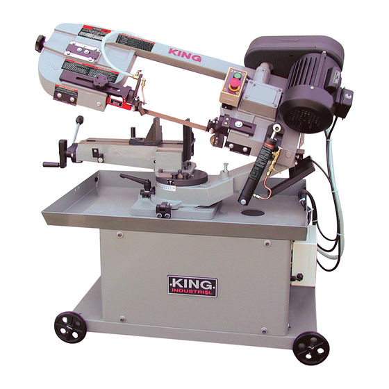
- Page 1 7”X 12” DUAL SWIVEL METAL CUTTING BANDSAW MODEL: KC-712DS INSTRUCTION MANUAL COPYRIGHT © 2004 ALL RIGHTS RESERVED BY KING CANADA TOOLS INC.
-
Page 2: Warranty Information
WARRANTY INFORMATION 2-YEAR KING CANADA TOOLS LIMITED WARRANTY OFFERS A 2-YEAR LIMITED WARANTY FOR INDUSTRIAL USE. FOR THIS 7” X 12” METAL CUTTING BANDSAW PROOF OF PURCHASE Please keep your dated proof of purchase for warranty and servicing purposes. REPLACEMENT PARTS Replacement parts for this tool are available at our authorized KING CANADA service centers across Canada. -
Page 3: Specific Safety Instructions
GENERAL & SPECIFIC SAFETY INSTRUCTIONS VOLTAGE WARNING: Before connecting the tool to a power source (receptacle, outlet, etc.) be sure the voltage supplied is the same as that specified on the nameplate of the tool. A power source with voltage greater than that for the specified tool can result in SERIOUS INJURY to the user - as well as damage to the tool. - Page 4 ELECTRICAL CONNECTIONS SPECIFICATIONS & STARTING WARNING! ALL ELECTRICAL CONNECTIONS MUST BE DONE BY A QUALIFIED ELECTRICIAN. ALL ADJUSTMENTS OR REPAIRS MUST BE DONE WITH THE MACHINE DISCONNECTED FROM THE POWER SOURCE. FAILURE TO COMPLY MAY RESULT IN SERIOUS INJURY! 220V POWER SUPPLY & OPERATION tool’s plug.
-
Page 5: Assembly And Operation
ASSEMBLY & OPERATION WORK SET UP 1. Raise the saw head to vertical position. 2. Open vise to accept the piece to be cut by rotating the wheel at the end of the base. 3. Place workpiece on saw bed. If the piece of long, support the end. 4. -
Page 6: Operation
OPERATION STARTING SAW CAUTION: NEVER OPERATE SAW WITHOUT BLADE GUARDS IN PLACE. Be sure the blade is not in contact with the work when the motor is started. Start the motor, allow the saw to come to full speed, then begin the cut by letting the head down slowly onto the work. - Page 7 OPERATION BI-METAL SPEEDS AND FEEDS MATERIAL ALLOY BAND SPEED The chart Fig.7 is a guide to cutting 4” (100mm) material (with a 3/4 ASTM NO. FT./MIN. M/MIN. Vari-Tooth) when using a cutting fluid. Copper 173, 932 330, 365 Alloy Increase band speed: 623, 624 15% When cutting 1/4”...
-
Page 8: Changing Blade
OPERATION CHANGING BLADE Raise Saw head to vertical position, lock cylinder and open the blade guards. Loosen tension screw knob sufficiently to allow blade with teeth slanting toward the motor as follows: 1. Place the blade in between each of the guide bearings. 2. -
Page 9: Blade Tracking Adjustment
OPERATION BLADE TRACKING ADJUSTMENT 1. Open the blade guard. 2. Remove the blade guide assemblies (top and bottom). 3. Loosen the hex bolts (A) Fig.10 in the tilting mechanism to a point where it is loose but snug. 4. With the machine running, adjust both the set screw (B) and blade tension knob (C) simultaneously to keep constant tension on the blade. -
Page 10: Operation And Maintenance
OPERATION & MAINTENANCE ADJUSTING HEAD PIVOT ANGLE The main head assembly can be pivoted in both directions (clockwise and counterclockwise) up to 45 degrees. To pivot head, first loosen pivot lock handle (A) Fig.12. Move head to the desired pivot angle using the angle scale (B) on the base. There are three degree positive stops which allow you to quickly set the head to predetermined angles.
Need help?
Do you have a question about the KC-712DS and is the answer not in the manual?
Questions and answers