
Related Manuals for King Industrial KC-10HCX


Summary of Contents for King Industrial KC-10HCX
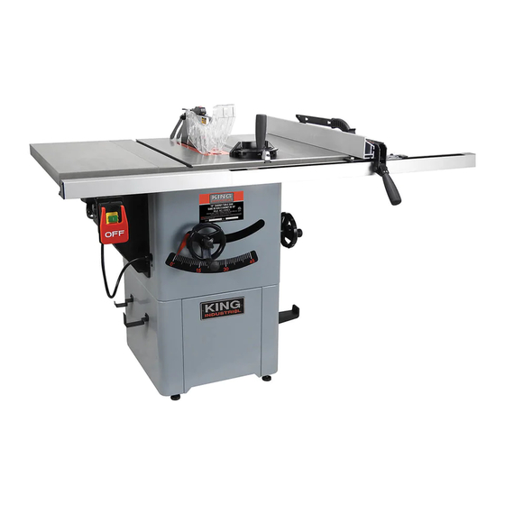
- Page 1 10” CABINET TABLE SAW WITH 30” RIP FENCE MODEL: KC-10HCX INSTRUCTION MANUAL COPYRIGHT © 2022 ALL RIGHTS RESERVED BY KING CANADA TOOLS INC.
-
Page 2: Warranty Information
WARRANTY INFORMATION 2-YEAR KING CANADA TOOLS LIMITED WARRANTY OFFERS A 2-YEAR LIMITED WARRANTY FOR THIS 10” CABINET TABLE SAW FOR INDUSTRIAL USE. PROOF OF PURCHASE Please keep your dated proof of purchase for warranty and servicing purposes. REPLACEMENT PARTS Replacement parts for this product are available at our authorized King Canada service centers across Canada. Please use the 10 digit part numbers listed in this manual for all part orders where applicable. - Page 3 GENERAL & SPECIFIC SAFETY INSTRUCTIONS FOR TABLE SAWS BEING PREPARED 9) Know your table saw. Learn the table saw’s operation, application 1) Wear proper apparel. Do not wear loose clothing, gloves, neckties, and specific limitations. rings, bracelets or other jewelry that may get caught in moving parts 10) Handle workpiece correctly.
-
Page 4: Think Safety
GENERAL & SPECIFIC SAFETY INSTRUCTIONS FOR TABLE SAWS PROTECTION: EYES, HANDS, FACE, BODY, EARS continued... ONLY USE ACCESSORIES DESIGNED FOR THIS TABLE SAW 5) Never place your face or body in line with the cutting tool (blade). 1) Cross-cutting operations are worked more conveniently with greater 6) Never place your fingers or hands in the path of the saw blade or safety if an auxiliary wood facing is attached to the miter gauge any other cutting tool. -
Page 5: Specifications
12. Blade tilting handwheel lock knob 26. Miter gauge storage 13. Angle scale 27. Rip fence storage hooks 14. Blade raising handwheel lock knob SPECIFICATIONS MODEL KC-10HCX Blade diameter 10” Blade tilts Left Depth of cut at 45 2-3/16” Depth of cut at 90 3-1/8”... - Page 6 ELECTRICAL REQUIREMENTS & SWITCH OPERATION WARNING! ALL ELECTRICAL CONNECTIONS MUST BE DONE BY A QUALIFIED ELECTRICIAN. FAILURE TO COMPLY MAY RESULT IN SERIOUS INJURY! ALL ADJUSTMENTS OR REPAIRS MUST BE DONE WITH THE MACHINE DISCONNECTED FROM THE POWER SOURCE. FAILURE TO COMPLY MAY RESULT IN SERIOUS INJURY! POWER SUPPLY (120V) PROPERLY GROUNDED 120V OUTLET...
-
Page 7: Assembling Stand
ASSEMBLY UNPACKING AND CLEANING TABLE & EXTENSIONS Open carton and remove all loose parts and the main assembly. To avoid any accidental starts, do not plug in power cord during the assembly and adjustment of this Table Saw. If any loose parts appear to be damaged, do not plug in power cord until the damaged parts are replaced, and the assembly and adjustment of the Table Saw is completed. -
Page 8: Installing Extension Tables
ASSEMBLY ASSEMBLING STAND TO CABINET 1) With the Table Saw still positioned upside down on its table. Position the stand assembly upside down onto the cabinet as shown in Fig.8. Make sure the front of the stand is facing the front of the Table Saw. Secure the stand to the cabinet using 8 carriage bolts, washers and hex. - Page 9 ASSEMBLY INSTALLING RIP FENCE RAILS (REAR & FRONT) & ON/OFF SWITCH Rear rails: 1) This Table Saw comes with a short rear rail (A) Fig.12 and a long rear rail (B) which get installed to the rear of the table and the extension tables. 2) While standing behind the Table Saw, install the short rear rail (A) Fig.12 to the right side of the table and extension table as shown, using 3 cap screws (C), washers and hex.
- Page 10 ASSEMBLY INSTALLING RIP FENCE RAILS (REAR & FRONT) & ON/OFF SWITCH Front rails (continued): 5) Now install the long front rail (A) Fig.16 to the opposite side of the table and extension table following the same steps as the short front rail. Slide the upper slot of the long front rail over 3 of the hex.
-
Page 11: Installing Blade
ASSEMBLY INSTALLING BLADE 1) Make sure the Table Saw is Off and the power cord is disconnected. 2) Remove the arbor nut (A) Fig.20 by turning it counterclockwise, then remove the blade flange (B). If the arbor nut is too tight to remove by hand, push spindle lock (C) towards the right to lock spindle shaft and use the supplied blade wrench to loosen arbor nut. -
Page 12: Assembly And Adjustments
ASSEMBLY & ADJUSTMENTS ADJUSTING RIP FENCE FRONT RAILS AND EXTENSION TABLES The rip fence rails were previously installed, but still require adjustment to align the “0” mark of the rail scale with the blade, and they need to be secured to the tables. The alignment of the extension tables also needs final adjustments. -
Page 13: Adjusting Riving Knife Alignment
ADJUSTMENTS & OPERATION ADJUSTING BLADE TILT POSITIVE STOPS 1) Raise blade to maximum height by turning blade height handwheel (B) Fig.8 clockwise. 2) Set blade 90º to the table by turning the blade tilting handwheel (D) Fig.28 counterclockwise as far as it will go. Do not force beyond stop. 3) Place a combination square (A) Fig.29 on the table and verify that blade is set at a perfect 90º... -
Page 14: Adjusting Rip Fence
ADJUSTMENTS & OPERATION ADJUSTING RIVING KNIFE ALIGNMENT continued... Blade proximity alignment: The gap between the blade and the riving knife must be between 3mm (0.12”) and 8mm (0.32”). Refer to Fig.33. If an adjustment is needed, note whether blade-to riving knife gap needs to be increased or decreased. Adjust as follows: 1) Disconnect machine from power source. -
Page 15: Dust Collection
ADJUSTMENTS & OPERATION ADJUSTMENTS CHECKING BLADE & TABLE ALIGNMENT This Table Saw is shipped from the factory with the table adjusted so the miter gauge T-slots are parallel with the blade. To ensure continued best results, periodically the blade and table alignment should be checked. 1) Measure the distance between the miter gauge T-slot and the front of the blade. -
Page 16: Operation
OPERATION CROSSCUTTING Crosscutting requires the use of the miter gauge to position and guide the work. Place the work against the miter gauge and advance both the miter gauge and work toward the saw blade, as shown in Fig.40. The miter gauge may be used in either table slot, however, most operators prefer the left groove for average work. -
Page 17: Maintenance
MAINTENANCE PUSH STICK CONSTRUCTION A push stick is supplied with this Table Saw and should be used whenever possible. If you misplace the push stick, illustration below shows how to make one yourself. It is recommended to use a good quality plywood or solid wood, 1/2” and 3/4” thick. FIGURE 44 REPLACING RIBBED BELT MAKE SURE THE POWER CORD IS DISCONNECTED FROM THE POWER... -
Page 18: Troubleshooting
TROUBLESHOOTING PROBLEM SOLUTION SAW WILL NOT START 1. Saw not plugged in. 1. Plug in saw. 2. Fuse blown or circuit breaker tripped. 2. Replace fuse or reset circuit breaker. 3. Cord damaged. 3. Have cord replaced by a certified electrician. OVERLOAD KICKS OUT FREQUENTLY 1.
Need help?
Do you have a question about the KC-10HCX and is the answer not in the manual?
Questions and answers