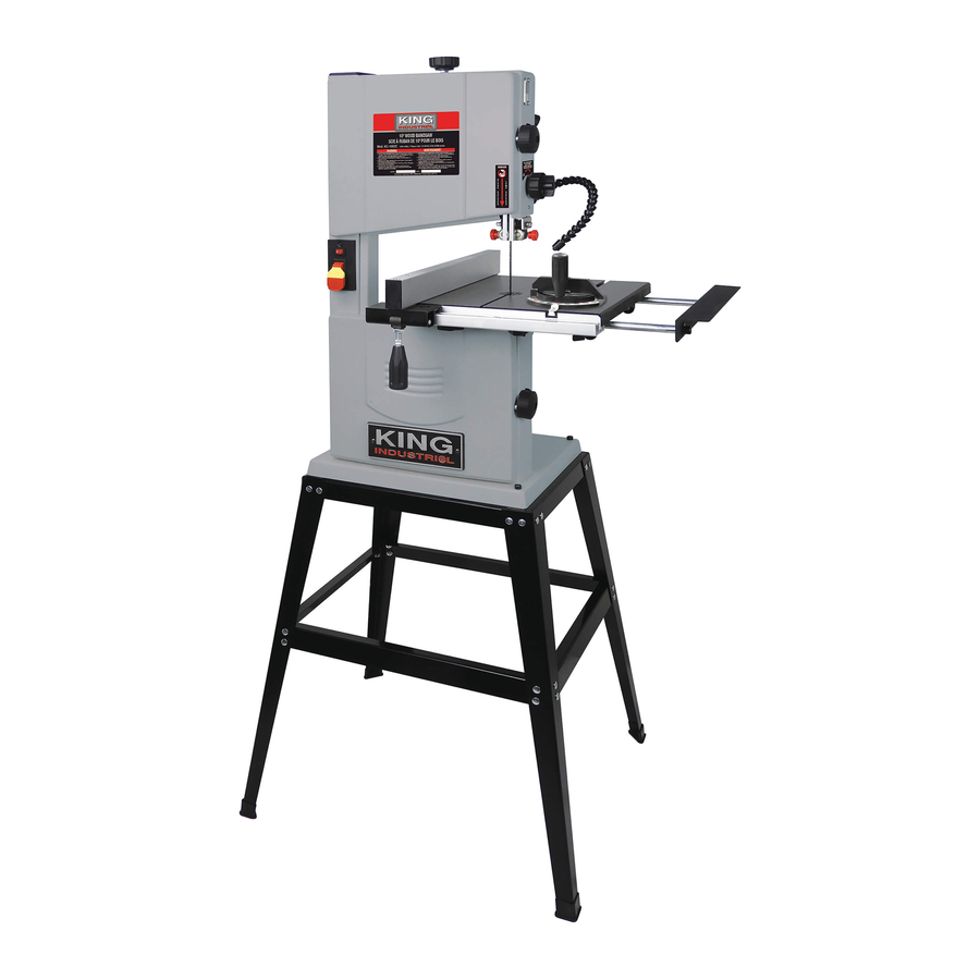
Summary of Contents for King Industrial KC-1002C
-
Page 1: Instruction Manual
10” WOOD BANDSAW WITH STAND INSTRUCTION MANUAL MODEL: KC-1002C COPYRIGHT © 2018 ALL RIGHTS RESERVED BY KING CANADA TOOLS INC. -
Page 2: Warranty Information
WARRANTY INFORMATION 2-YEAR kING CANADA TOOLS LIMITED WARRANTY OFFERS A 2-YEAR LIMITED WARRANTY FOR THIS 10” WOOD BANDSAW INTENDED FOR NON COMMERCIAL USE PROOF OF PURCHASE Please keep your dated proof of purchase for warranty and servicing purposes. PARTS DIAGRAM & PARTS LISTS Refer to the Parts section of the King Canada web site for the most updated parts diagram and parts list. -
Page 3: General Safety Rules
GENERAL SAFETY RULES 1. kNOW YOUR TOOL 12. ALWAYS WEAR SAFETY GLASSES. Read and understand the owners manual and labels affixed to Always wear safety glasses (ANSI Z87.1). Everyday eye-glasses only have impact resistant lenses, thet are NOT the tool. Learn its application and limitations as well as its specific potential hazards. -
Page 4: Specific Safety Rules
SPECIFIC SAFETY RULES Safety is a combination of common sense, staying alert and • Use extra supports (tables, blocks, etc...) for any workpieces knowing how your bandsaw works. Read and understand the large enough to tip when not held down to the table top. following safety rules before operating. - Page 5 21. Bevel scale and pointer. This angle scale indicates the table angle for bevel cuts. 22. Table lock handle. Loosening this handle allows the table to be tilted for bevel cutting. 23. Motor. Specifications MODEL KC-1002C Cutting capacity frame to blade 9-1/2” Maximum depth of cut 4-1/8”...
-
Page 6: Electrical Information
ELECTRICAL INFORMATION WARNING! ALL ELECTRICAL CONNECTIONS MUST BE DONE BY A QUALIFIED ELECTRICIAN. FAILURE TO COMPLY MAY RESULT IN SERIOUS INJURY! ALL ADJUSTMENTS OR REPAIRS MUST BE DONE WITH THE MACHINE DISCONNECTED FROM THE POWER SOURCE. FAILURE TO COMPLY MAY RESULT IN SERIOUS INJURY! POWER SUPPLY PROPERLY GROUNDED OUTLET WARNING: YOUR BANDSAW MUST BE CONNECTED TO A 110V-120V,... -
Page 7: Assembling Stand
ASSEMBLY WARNING: To avoid injury, if any parts are missing, do not attempt to assemble the bandsaw, plug in the power cord, or turn the switch on, until the missing parts are obtained and installed correctly. WARNING: For your own safety, never connect plug to power source outlet, or insert switch key until all assembly steps are complete and until you have read and understood the entire instruction manual. - Page 8 ASSEMBLY INSTALLING RIP FENCE RAIL AND RIP FENCE 1) Install guide rail (A) Fig.6 to the front of table. Secure the guide rail using the four lock knobs (B) under the table. FIGURE 6 2) Slide rip fence assembly (A) Fig.7 onto the table. The rear hook should engage the rear of the table.
-
Page 9: Operation & Adjustments
OPERATION & ADJUSTMENTS WARNING! Turn off the saw, remove the main On/Off switch safety key and unplug the power cord before making any adjustments on the saw. ADJUSTING TABLE 90 TO THE BLADE 1) The table stop (A) Fig.10 is set at the factory to stop the table at 90º (perpendicular) with the blade. -
Page 10: Adjusting Blade Tension
OPERATION & ADJUSTMENTS WARNING! Turn off the saw, remove the main On/Off switch safety key and unplug the power cord before making any adjustments on the saw. ADJUSTING BLADE TENSION The blade tension knob (B) Fig.13 is used to adjust blade tension. The quick release tension lever (A) Fig.13 must be engaged (moved to the left) before making blade tension adjustments with the blade tension knob (B). - Page 11 OPERATION & ADJUSTMENTS WARNING! Turn off the saw, remove the main On/Off switch safety key and unplug the power cord before making any adjustments on the saw. ADJUSTING BLADE GUIDE ASSEMBLIES Adjustments are performed in the same manner for each blade guide assembly. Each assembly must be adjusted in turn using the following adjustment procedures.
-
Page 12: Operation And Maintenance
OPERATION & MAINTENANCE DUST COLLECTION This bandsaw comes with a versatile dust chute (A) Fig.20 which accepts 2”, 2-1/2” and 4” dust collection hoses. Note: Wood dust and chips in a confined area can give rise to fire or an explosion. keep ignition sources away from bandsaw. keep saw dust to a minimum by cleaning the inside of the bandsaw after every use.


Need help?
Do you have a question about the KC-1002C and is the answer not in the manual?
Questions and answers