Table of Contents
Advertisement
Quick Links
Download this manual
See also:
Service Manual
Advertisement
Table of Contents

Related Manuals for King Industrial KC-1802FXB


Summary of Contents for King Industrial KC-1802FXB
-
Page 1: Instruction Manual
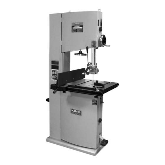
DELUXE 18” WOOD BANDSAW 06/2017 INSTRUCTION MANUAL MODEL: KC-1802FXB COPYRIGHT © 2017 ALL RIGHTS RESERVED BY KING CANADA TOOLS INC. -
Page 2: Warranty Information
WARRANTY INFORMATION 2-YEAR KING CANADA TOOLS LIMITED WARRANTY OFFERS A 2-YEAR LIMITED WARRANTY FOR THIS 18” WOOD BANDSAW FOR COMMERCIAL USE. PROOF OF PURCHASE Please keep your dated proof of purchase for warranty and servicing purposes. REPLACEMENT PARTS Replacement parts for this product are available at our authorized King Canada service centers across Canada. LIMITED TOOL WARRANTY King Canada makes every effort to ensure that this product meets high quality and durability standards. -
Page 3: Safety Instructions
GENERAL & SPECIFIC SAFETY INSTRUCTIONS 12. ALWAYS WEAR SAFETY GLASSES. 1. KNOW YOUR TOOL Read and understand the owners manual and labels affixed to Always wear safety glasses (ANSI Z87.1). Everyday eyeglasses only have impact resistant lenses, thet are NOT safety glasses. the tool. -
Page 4: Electrical Information
ELECTRICAL INFORMATION AND CONTROL PANEL WARNING! ALL ELECTRICAL CONNECTIONS MUST BE DONE BY A QUALIFIED ELECTRICIAN. FAILURE TO COMPLY MAY RESULT IN SERIOUS INJURY! ALL ADJUSTMENTS OR REPAIRS MUST BE DONE WITH THE BANDSAW DISCONNECTED FROM THE POWER SOURCE. FAILURE TO COMPLY MAY RESULT IN SERIOUS INJURY! GENERAL INFORMATION- 220V single phase operation Once the key is turned to the On (I) position, the power on light (C) will turn on indicating the wood bandsaw is connected to a... - Page 5 3/4” x 145-5/8” x .032” KBB-1810-2 1” x 145-5/8” x .032” KBB-1825-2 1-1/4” x 145-5/8” x .035” *Standard blade included MODEL KC-1802FXB 17-5/8” Cutting capacity frame to blade Table size 24” x 20” Table height from floor 37-1/8” Blade size 145-5/8”...
- Page 6 ASSEMBLY UNPACKING Unpack and remove the bandsaw and all loose parts from the crate. The table is covered with a protective grease to prevent rusting during transport, clean it with a degreaser. To ensure sufficient stability and security, bolt the base of the bandsaw to the floor using the 4 mounting holes (mounting hardware not included).
-
Page 7: Assembly And Adjustments
ASSEMBLY & ADJUSTMENTS Installing Tru-Rip rip fence system 1. Mount the large front rail mounting brackets (A) Fig.8 to the front of the table using hex. bolts and washers. 2. Mount lock knobs (B) and flat square nuts (C) to the mounting brackets as shown. - Page 8 ASSEMBLY & ADJUSTMENTS Installing Tru-Rip rip fence system continued... 7. Position the rip fence (A) Fig.12 onto the front and rear rails. Lower the front handle (B) to lock rip fence into position. 8. A wooden face attachment (C) Fig.12 can be installed to the rip fence when supporting taller workpieces is needed.
- Page 9 ADJUSTMENTS Installing/removing blade This bandsaw comes with a 145-5/8” long x 3/4” wide wood cutting bandsaw blade. A wide range of blade widths can be installed on this bandsaw, 1/4”- 3/8” wide blades can be used for small tighter radius curves, 1/2” - 1-1/4” wide blades can be used for larger radius curves or cutting thicker workpieces.
- Page 10 ADJUSTMENTS Adjusting tension of the blade Determining ideal blade tension is somewhat subjective. It is learned through practice and experience and is somewhat dependant on personal preference and individual work habits. 1. The blade tension must be set depending on the blade width, at the rear of the bandsaw is a hydraulic blade tension gauge (B) Fig.19.
- Page 11 ADJUSTMENTS Adjusting the upper and lower blade guides assemblies The blade guide bakelite blocks (A) Fig.22 and bearings (B) in both the upper and lower blade guides prevent the blade from moving from side to side during operation and must be snug but not touching the blade, this will ensure accurate cuts.
- Page 12 ADJUSTMENTS Adjusting the position of the upper and lower thrust bearing The upper and lower thrust bearing keep the blade from moving back and out of position when the workpiece is being fed into the blade and must be very close to the back of the blade to prevent damage to the blade during cutting.
-
Page 13: Operation And Maintenance
OPERATION & MAINTENANCE Dust collection It is recommended that the bandsaw be connected to a dust collector. This will avoid a dusty and undesired work environment. There are two 4” dust ports (A) Fig.30. 4” dust collection hoses must be attached to the dust ports using 4”... -
Page 14: Maintenance
MAINTENANCE MAINTENANCE Replacing blade guide bearings, thrust bearings and Bakelite blocks It is recommended to inspect the blade guide bearings and thrust bearings each time the blade is replaced to make sure they turn freely. If not, the blade will get stuck or jammed between them and will wear prematurely. Replace the blade guide bearings and thrust bearing as follows: 1. -
Page 15: Electrical Diagram
ELECTRICAL DIAGRAM MODEL KC-1802FXB...
Need help?
Do you have a question about the KC-1802FXB and is the answer not in the manual?
Questions and answers