Table of Contents
Advertisement
Quick Links
Power Tools Service Manual
PRODUCT NAME
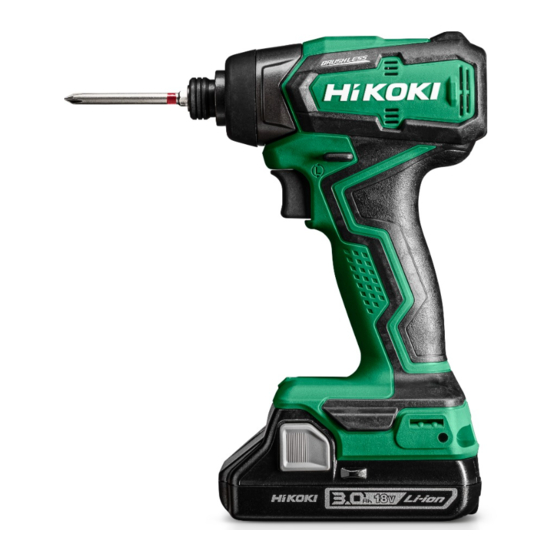
18 V Cordless Impact Driver
WH 18DD, WH 18DDX
Models
CONTENTS
REPAIR GUIDE ---------------------------------------------------------------------------------------------------------------- 1
1. Precautions on disassembly and reassembly ----------------------------------------------------------- 1
• Disassembly ---------------------------------------------------------------------------------------------------- 1
• Reassembly ---------------------------------------------------------------------------------------------------- 4
• Type of silicone rubber --------------------------------------------------------------------------------------- 8
• Lubrication points and type of lubricant ------------------------------------------------------------------ 8
• Tightening torque ---------------------------------------------------------------------------------------------- 9
• Checking after reassembly --------------------------------------------------------------------------------- 9
• No-load current ------------------------------------------------------------------------------------------------ 9
• Wiring diagram ----------------------------------------------------------------------------------------------- 10
2. Precautions on disassembly and reassembly of the charger -------------------------------------- 10
CONFIDENTIAL
WH 18DDX: For the UK
WH 18DD: For other regions
WH 18DD
Overseas Sales Management Dept.
Jul. 2020
Page
W
Advertisement
Table of Contents

Subscribe to Our Youtube Channel
Related Manuals for Hitachi Koki WH 18DD


Summary of Contents for Hitachi Koki WH 18DD
-
Page 1: Table Of Contents
PRODUCT NAME 18 V Cordless Impact Driver WH 18DD, WH 18DDX Models WH 18DDX: For the UK WH 18DD: For other regions CONTENTS Page REPAIR GUIDE ---------------------------------------------------------------------------------------------------------------- 1 1. Precautions on disassembly and reassembly ----------------------------------------------------------- 1 • Disassembly ---------------------------------------------------------------------------------------------------- 1 •... -
Page 2: Repair Guide
1. Precautions on disassembly and reassembly [Bold] numbers in the description below correspond to the item numbers in the parts lists and exploded assembly diagrams for the Models WH 18DD and WH 18DDX. Disassembly 1. Removal of the guide sleeve Remove the Retaining Ring [2], Washer (D) [3], Guide Spring (D) [4], and Guide Sleeve (D) [5] in this order with a small flat-blade screwdriver. - Page 3 2. Removal of the exterior parts Insert the edge of a small flat-blade screwdriver into the space between the Front Cap [6] and the Hammer Case [7], and remove the Front Cap [6] from the Hammer Case [7]. 3. Removal of housing (A).(B) set (1) Remove the nine Tapping Screws (W/Flange) D3 x 16 [27] to remove housing (B) of Housing (A).(B) Set [33].
- Page 4 5. Removal of the inner cover Detach Ring Gear (A) [23] and O-ring [24] from the Inner Cover [26], and then use a small flat-blade screwdriver to remove Damper (A) [25]. NOTE: Be careful not to damage the O-ring [24]. •...
-
Page 5: Reassembly
Reassembly Generally, perform reassembly by reversing the disassembly procedure. However, special attention should be given to the following items. 1. Reassembly of the power supply unit and its vicinity • Reassembly of the power supply unit and its vicinity [30] Fit the protrusion of the direction selector lever of the switch into the hole of the Pushing Button [30]. - Page 6 2. Mounting the mechanical parts (1) Mount Washer (S) [16] to the Spindle [18]. Put the twenty-eight Steel Balls D3.175 [13], Washer (J) [14], and Hammer Spring [15] in the Hammer [12], and mount it to the Spindle [18]. (2) Align the highest point of the cam groove in the Spindle [18] with the steel ball insertion groove in the Hammer [12].
- Page 7 Inner Cover [26] are not positioned at 90° relative to the retaining tabs of the Hammer Case [7], reassemble it. The Models WH 18DD and WH 18DDX are structured so that the Hammer Case [7] will retain the parts axially when properly assembled.
- Page 8 • Mounting the hammer case Retaining tabs Make the retaining tabs of the Hammer Case [7] touch housing (A) here. Make sure the Hammer Case [7] is securely fitted to housing (A).
-
Page 9: Type Of Silicone Rubber
4. Mounting the exterior parts Mount the Front Cap [6] to the Hammer Case [7]. 5. Mounting the guide sleeve Put the two Steel Balls D3.5 [9] into the Anvil [10]. Mount • Mounting the guide sleeve Guide Sleeve (D) [5], Guide Spring (D) [4], and Washer (D) Press down here. -
Page 10: Tightening Torque
Checking after reassembly After reassembly, check the following. (1) Check that the Models WH 18DD and WH 18DDX run smoothly and start, stop, change speed, and change direction securely. (2) Check that the rotating direction of the Anvil [10] matches that of the pushed side of the Pushing Button [30]. -
Page 11: Wiring Diagram
Wiring diagram • Wiring diagram Push the internal wire into this groove. DC-speed control switch [32] • Connecting diagram LD (green) - (black) Battery terminal + (red) Controller DC-speed control switch 2. Precautions on disassembly and reassembly of the charger Refer to the Service Manual for precautions on disassembly and reassembly of the charger Models UC 18YFSL and UC 18YKSL. - Page 12 M O D E L WH18DD Rev.1...
- Page 13 ITEM CODE DESCRIPTION REMARKS USED 375143 GUIDE SLEEVE ASS'Y INCLUD. 2-5, 9 330619 RETAINING RING 330856 WASHER (D) 331284 GUIDE SPRING (D) 322717 GUIDE SLEEVE (D) 337360 FRONT CAP 375003 HAMMER CASE 336639 WASHER (F) 319535 STEEL BALL D3.5 (10 PCS.) 374395 ANVIL (A) 374396 ANVIL (B) FOR EUROPE, AUS, NZL...
Need help?
Do you have a question about the WH 18DD and is the answer not in the manual?
Questions and answers