
Related Manuals for Adleepower MS2-107


Summarization of Contents
Preface
General Precautions
General safety and handling precautions for the inverter.
Safety Symbols
Explanation of warning and caution symbols used in the manual.
Receiving and Inspection
Name Plate Description
Detailed explanation of the information presented on the inverter's name plate.
Dimension Drawings
Inverter Dimensions (Fig 1)
Dimensional views and measurements of the inverter unit.
Inverter Dimensions (Fig 2)
Dimensional views and measurements of the inverter unit.
Inverter Dimensions (Fig 3)
Dimensional views and measurements of the inverter unit.
Inverter Dimensions (Fig 4)
Dimensional views and measurements of the inverter unit.
Installation Guidelines
Installation Site and Mounting
Key considerations for selecting an installation site and mounting the inverter correctly.
Terminal Descriptions
Main Circuit Connection Diagrams
Diagrams illustrating main circuit connections for various inverter models.
Control Circuit Terminals
Detailed descriptions of control circuit terminal functions.
RS485 Connector
Information regarding the RS485 communication connector.
Hardware Setting and Jumpers
Explanation of hardware settings and jumper configurations for different models.
Jumper Setup (MS1/MS2 Models)
Jumper setup configurations for MS1 and MS2 models.
Jumper Setup (MS4 Models)
Jumper setup configurations for MS4 models.
Jumper Setup (MS2/MS4 Models)
Jumper setup configurations for MS2 and MS4 models.
Wiring and Connections
Main Circuit Wiring
Guidelines and precautions for wiring the main circuit of the inverter.
Wiring Equipment Selection
Guidance on selecting appropriate wiring equipment and cable sizes.
Surge Absorber Recommendations
Recommendations for surge absorber usage to prevent malfunctions.
Cable Size and Length Selection
Guidelines for selecting cable size and length based on motor distance.
Main Circuit Wiring Precautions
Important wiring precautions for the main circuit of the inverter.
Control Signal Circuit Wiring
Best practices for wiring control signal circuits, separating them from power cables.
Grounding Procedures
Proper methods for grounding the inverter and motor for safety.
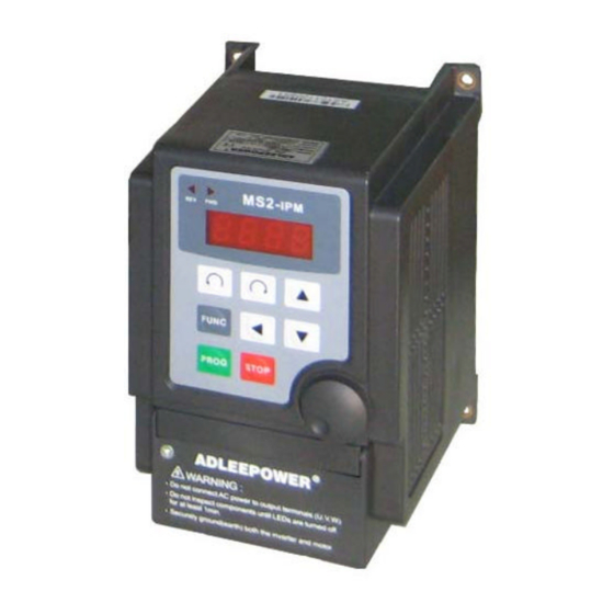
Digital Operation Panel
Operation Keys and Functions
Description of the keys on the operation panel and their respective functions.
Functions Description
Function Codes CD00-CD17
Detailed descriptions and default values for function codes CD00 to CD17.
Function Codes CD18-CD37
Detailed descriptions and default values for function codes CD18 to CD37.
Function Codes CD38-CD59
Detailed descriptions and default values for function codes CD38 to CD59.
Function Codes CD60-CD95
Detailed descriptions and default values for function codes CD60 to CD95.
Communication Address Settings
Description of communication address settings and parameters.
Operating Modes
Panel Operation
How to operate the inverter using the control panel.
F306 Operation Mode
Operating instructions for the F306 mode.
RS485 Communication Control
Instructions for controlling the inverter via RS485.
Terminal Control
How to control the inverter using external terminals.
Function Settings: Speed and Time
First Speed Setting (CD00)
Setting the initial operating speed of the inverter.
Parameter Locking (CD01)
Function to prevent unauthorized changes to inverter parameters.
Acceleration Time 1 (CD02)
Setting the acceleration time for the motor.
Deceleration Time 1 (CD03)
Setting the deceleration time for the motor.
Jogging Frequency (CD04)
Setting the frequency for jog operation mode.
Start Frequency (CD05)
Setting the initial frequency when the inverter starts.
Function Settings: Modes and Signals
Jog Mode (CD06)
Configuring the jog operation mode.
Frequency Meter Correspondence (CD07)
Setting the output for frequency meter indication.
Motor Rotation Direction (CD08)
Setting the motor rotation direction (CW, CCW, or both).
Function Settings: Control Inputs
Analog/Digital Frequency Input (CD10)
Selecting between analog or digital frequency input.
Dynamic Brake/Free Running (CD11)
Configuring dynamic braking or free running operation.
Terminal/Keypad Command Control (CD12)
Selecting command source between terminal and keypad.
Function Settings: Frequency Limits
Source Operation Command (CD13)
Setting the source for operation commands (Normal, F306, RS485).
Maximum Frequency Limit (CD14)
Setting the upper limit for the output frequency.
Minimum Frequency Limit (CD15)
Setting the lower limit for the output frequency.
Function Settings: Display and Frequency
Frequency Display Scale (CD16)
Setting the scaling for frequency display, including RPM calculation.
1st Maximum Voltage Frequency (CD17)
Setting the first maximum voltage frequency limit.
Function Settings: V/F and Braking
V/F Pattern Setting (CD18)
Configuring the Voltage/Frequency (V/F) curve patterns.
DC Braking Time (CD19)
Setting the duration for DC braking.
Function Settings: Braking and Speed
DC Braking Power (CD20)
Adjusting the power level for DC braking.
Torque Boost (CD21)
Setting torque boost to compensate for stator resistance.
Second Speed Setting (CD22)
Setting the second preset speed for the inverter.
Third Speed Setting (CD23)
Setting the third preset speed for the inverter.
Function Settings: Speed and Time
Fourth Speed Setting (CD24)
Setting the fourth preset speed for the inverter.
Acceleration Time 2 (CD25)
Setting the second acceleration time parameter.
Deceleration Time 2 (CD26)
Setting the second deceleration time parameter.
Function Settings: Frequency and Gain
Carrier Frequency (CD27)
Setting the carrier frequency to reduce noise and improve efficiency.
Output Voltage Gain (CD28)
Adjusting output voltage gain for energy-saving operation.
Frequency Jump 1 (CD29)
Setting the first frequency jump point.
Function Settings: Frequency Jumps
Frequency Jump 2 (CD30)
Setting the second frequency jump point.
Frequency Jump 3 (CD31)
Setting the third frequency jump point.
Jump Range (CD32)
Defining the frequency range for jumps.
Function Settings: Frequency Control
Frequency Reference Bias (CD33)
Setting bias for frequency reference with gradient adjustment.
Frequency Reference Bias Direction (CD34)
Setting the polarity for frequency reference bias.
Frequency Gain (CD35)
Adjusting the gain for the analog input frequency.
Error Records
Latest Error Record (CD36)
Displays the most recent error code.
Error Record 1 (CD37)
Stores the first error code.
Error Record 2 (CD38)
Stores the second error code.
Error Record 3 (CD39)
Stores the third error code.
Error and Terminal Settings
Clear Error Records (CD40)
Clears stored error codes.
HZ/RPM Display (CD41)
Selects display mode between frequency (HZ) and RPM.
FT1 Multi-Function Terminal 1 (CD42)
Configures functions for FT1 terminal.
Terminal Settings
FT2 Multi-Function Terminal 2 (CD43)
Configures functions for FT2 terminal.
Speed and Analog Terminal Settings
Free Analog Terminal 1 (CD44)
Assigns functions to the FA1 analog terminal.
Run Frequency Setting (CD46)
Sets the frequency for the run terminal output signal.
Speed Settings
5th Speed Setting (CD47)
Sets the fifth preset speed.
6th Speed Setting (CD48)
Sets the sixth preset speed.
Speed and Control Settings
7th Speed Setting (CD49)
Sets the seventh preset speed.
8th Speed Setting (CD50)
Sets the eighth preset speed.
Dynamic Braking Energy Limit (CD51)
Sets the limit for dynamic braking energy.
Version Selector (CD52)
Selects the inverter's operating version (e.g., 50Hz/60Hz).
Curve and Signal Settings
S-Curve Setting (CD53)
Configures the S-curve for non-linear acceleration/deceleration.
4-20mA Speed Command (CD54)
Configures speed control using a 4-20mA current signal.
Signal Range and Frequency Settings
Frequency Arrive Signal Range (CD55)
Sets the acceptable range for the frequency arrive signal.
2nd Maximum Voltage Frequency (CD56)
Sets the second V/F curve preset.
Timer and Control Settings
Timer FWD/REV Setting (CD57)
Configures forward/reverse operation timing sequences.
Auto Running Mode (Timer)
Auto Running Mode Configuration (CD58)
Sets up automatic multi-speed operation sequences with timers.
Timer Settings
Step Timer Settings (CD59-CD63)
Sets the running time for each speed step in timed sequences.
Timer and Communication Settings
Timer Unit Selector (CD64)
Selects the unit for timer settings (hr.min or min.sec).
Communication Loss Time (CD72)
Sets the time limit for communication loss detection.
Communication Error Counter (CD73)
Sets the threshold for continuous communication errors.
Address Setting (CD74)
Assigns a unique address for RS485 communication.
Communication Protocol Settings
Transmission Speed (CD75)
Sets the communication speed for RS485.
Transmission Fault Treatment (CD76)
Defines how the inverter responds to transmission faults.
Communicator Protocol (CD78)
Selects the communication protocol (RTU, ASCII).
Communication Protocol Details
RTU Protocol Format
Details of the RTU communication protocol format.
ASCII Protocol Format
Details of the ASCII communication protocol format.
Communication Codes and Commands
ASCII Code Description
Table of ASCII character codes used in communication.
Read AC Drive Settings (03H)
Procedure for reading inverter settings using function code 03H.
Communication Command Examples
RTU and ASCII Read Examples
Examples illustrating read operations using RTU and ASCII protocols.
Communication Data Processing
Integer Number Processing
Method for processing integer values in hexadecimal format.
Decimal Number Processing
Method for processing decimal values in hexadecimal format.
Write Parameter Settings (06H)
Procedure for writing parameter settings into the inverter.
Communication Write Examples
RTU and ASCII Write Examples
Examples of writing parameters via RTU and ASCII protocols.
Communication Loop Detection
Loop Detection Procedure
Procedure for detecting communication loop.
Communication Loop Detection Examples
Loop Detection Write Examples
Examples of writing data for communication loop detection.
Communication Checksum Methods
Cyclical Redundancy Check (CRC)
Explanation of the CRC calculation method.
Longitudinal Redundancy Check (LRC)
Explanation of the LRC calculation method.
Communication Error Response
Communication Error Codes
Definitions and descriptions of communication error codes.
RTU Error Response Format
AC drive response format for communication errors in RTU mode.
ASCII Error Response Format
AC drive response format for communication errors in ASCII mode.
Display Error Codes
Inverter Self-Checking Errors
List and descriptions of internal inverter self-checking error types.
Noise Protection Errors
Errors related to noise protection and self-test failures.
Power Device Failure Errors (PF01-PF04)
Troubleshooting steps for power device failure errors.
Operation Errors
List and descriptions of operational errors.
Parameter Locked Error (OPE1)
Indicates when parameters are locked.
Direction Control Error (OPE2)
Error related to motor direction limiting.
Analog Signal Input Error (OPE3)
Error related to analog signal input for speed command.
Terminal Command Error (OPE4)
Error when run command is from control terminal only.
Over Range Error (OPE5)
Indicates operating error messages exceeding limits.
Logic Error Warning (OPE6)
Warning for logic errors during setting.
Standby-Only Change Error (OPE7)
Indicates parameters can only be changed in standby.
Read-Only Parameter Error (OPE8)
Indicates parameters cannot be changed by the user.
Communication Error (OPE9)
Indicates a communication error.
Over Heat Warning (OH)
Indicates over-temperature condition for external indicator.
Over Load Warning (OL)
Indicates motor overload condition.
Precautions
Maintenance Precautions
Essential checks and safety measures before performing inverter maintenance.
Application Precautions
Safety and operational precautions for using the inverter with a motor.
Troubleshooting Guide
No Display Errors
Steps to diagnose and resolve issues when the inverter display is off.
Power Device Failure Errors (PF01-PF04)
Troubleshooting steps for power device failure errors.
EEPROM Errors (EEP1, EEP2)
Steps to resolve EEPROM access and check-sum errors.
Application Examples
2-Stage Speed Setting Example
Example of configuring two-stage speed control using a rheostat.
Normal/Jog Operation Example
Example demonstrating normal and jog operation mode setup.
Multi-Speed/Time Programming Example
Example for setting up automatic multi-speed operation with timed sequences.
8-Speed Terminal Control Example
Example of configuring eight-speed selection via terminal control.
Inverter Selection
Inverter Capacity Check Method
Methodology for determining and selecting the appropriate inverter capacity.
Appendix
Optional Braking Resistor
Specifications and selection guide for optional braking resistors.
ADLEEPOWER Service Office
Service Office - Taiwan
Contact details for ADLEEPOWER service in Taiwan.
Service Office - Hong Kong
Contact details for ADLEEPOWER service in Hong Kong.
Service Office - Guang Dong (China)
Contact details for ADLEEPOWER service in Guang Dong, China.
Service Office - Wu Han (China)
Contact details for ADLEEPOWER service in Wu Han, China.
Service Office - Shanghai (China)
Contact details for ADLEEPOWER service in Shanghai, China.
Need help?
Do you have a question about the MS2-107 and is the answer not in the manual?
Questions and answers