Table of Contents
Advertisement
Advertisement
Table of Contents

Related Manuals for Hioki IR4051


Summary of Contents for Hioki IR4051
- Page 1 IR4051 IR4052 IR4053 Instruction Manual INSULATION TESTER Video Scan this code to watch an instructional video. Carrier charges may apply. May 2018 Revised edition 7 IR4051A981-07 18-05H GlobalTestSupply www. .com Find Quality Products Online at: sales@GlobalTestSupply.com...
-
Page 2: Table Of Contents
Contents Contents Introduction ............... 1 Verifying Package Contents........1 Options..............3 Safety Information ............. 5 Operating Precautions ..........9 Chapter 1 Overview Product Overview ........13 Features ............ 13 Names and Functions of Parts ....15 Using a Carrying Case ......20 Chapter 2 Measurement Procedures Measurement Preparations ....... - Page 3 Contents Insulation Resistance Measurement ..27 2.5.1 Lock Function ........ 28 2.5.2 Measuring Insulation Resistance... 30 2.5.3 Switching the Number of Display Digits ..........32 2.5.4 Displaying 1-min. Values ....34 2.5.5 Voltage Characteristic of Measuring Terminals ........35 Discharging Function ........ 36 Voltage Measurement .......
-
Page 4: Introduction
Introduction Introduction Thank you for purchasing the HIOKI Model IR4051, IR4052, IR4053 Insulation Tester. To obtain maximum performance from the instrument, please read this manual first, and keep it handy for future reference. The “instrument” in this manual means IR4051, IR4052, or IR4053. - Page 5 Neck strap (Included with the IR4051 and IR4053.) ×1 LR6 alkaline battery ×4 * L9787 Test Lead and L9788-11 Test Lead Set with Remote Switch are all exclusively designed for the HIOKI IR4000 series. Do not use for any other purpose. GlobalTestSupply www.
-
Page 6: Options
Carrying case for the IR4052 L9787 Test Lead, L9788-10 Test Lead with Remote Switch (Red) and L9788-11 Test Lead Set with Remote Switch are all exclusively designed for the HIOKI IR4000 series. Do not use for any other purpose. GlobalTestSupply www. -
Page 7: Safety Information
Safety Information Safety Information This instrument is designed to conform to IEC 61010 Safety Standards, and has been thoroughly tested for safety prior to shipment. However, using the instrument in a way not described in this manual may negate the provided safety features. Before using the instrument, be certain to carefully read the fol- lowing safety notes. - Page 8 Safety Information Safety Symbols This manual contains information and warnings essential for safe operation of the instrument and for maintaining it in safe operating condition. Before using it, be sure to carefully read the following safety precautions. In the manual, the symbol indicates particularly important information that the user should read before using the instrument.
- Page 9 Indicates a prohibited action. (p. ) Indicates the location of reference information. Indicates that descriptive information is provided below. Indicates a function of the IR4051 Insulation Tester. IR4051 Indicates a function of the IR4052 Insulation Tester. IR4052 Indicates a function of the IR4053 Insulation Tester.
- Page 10 Safety Information Accuracy We define measurement tolerances in terms of rdg. (reading) and dgt. (digit) values, with the following meanings: rdg. (reading or displayed value) The value currently being measured and indicated on the measuring instrument. rdg. (reading or displayed value) The smallest displayable unit on a digital measuring instrument, i.e., the input value that causes the digital display to show a “1”...
-
Page 11: Operating Precautions
If you find any damage, contact your authorized Hioki distributor or reseller. To prevent an electric shock accident, confirm that the white or red portion (insulation layer) inside the cable is not exposed. - Page 12 Operating Precautions • The maximum rated voltage between input terminals and ground is 600 V DC/AC (CAT III). Attempting to measure voltages exceeding 600 V DC/AC with respect to ground could damage the instrument and result in personal injury. • 1000 V or 600 V may be labeled depending on the supplied test leads, but this is the rating of the test lead and not the rating performance of this instrument.
- Page 13 Operating Precautions • Please only use batteries for electrical supply. Any other electrical supply may damage the instrument and tested object and cause electric shock. • Persons wearing electronic medical devices such as a pacemaker should not use the 9804-02 Magnetic Adapter with magnet (option).
- Page 14 Operating Precautions • This instrument is designed for use indoors. It can be operated at temperatures between -25°C and 65°C (for IR4053, between 0°C and 50°C) without degrading safety. • For safety reasons, when taking measurements, only use the L9787, L9788-11 or optional test lead provided with the instrument. •...
-
Page 15: Overview
1.1 Product Overview Overview Chapter 1 1.1 Product Overview This instrument is an insulation ohmmeter that shortens work times associated with insulation testing. It is not designed for use on manufacturing lines and should not be used in such applications. For manufacturing line applications, use the ST5520 Insulation Tester. - Page 16 1.2 Features High-accuracy voltage measurement function Since the instrument incorporates a DC/AC voltmeter with the same accuracy as a card tester, there is no need to switch to a card tester when you need to measure voltage. IR4052 User-selectable number of display digits The instrument’s number of display digits can be changed.
-
Page 17: Names And Functions Of Parts
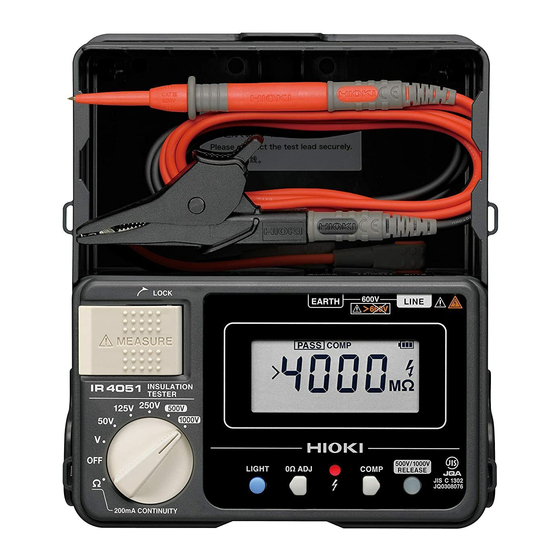
1.3 Names and Functions of Parts 1.3 Names and Functions of Parts Front Panel Terminals (on top) Terminals for control- IR4051 IR4052 ling Model L9788-10. *This figure is model “2. Measurement Display (p.23) (p.23) Procedures” Measure key EARTH terminal LINE terminal... - Page 18 1.3 Names and Functions of Parts Display IR4052 Bar graph Measured value Comparator judgment reference value or 1-minute value Indicates the remaining battery life as one of three levels. The battery mark outline will flash when the remaining battery life reaches 0, at which point the instrument will no longer perform measurement.
- Page 19 Turns on when the instrument is set to the 500 V range or the 1000 V range. Pressing turns off the indicator and enables insulation measurement. Display IR4051 Measured value or Comparator reference value Lights up when the criterion for the comparator function is indicated.
- Page 20 500 V or 1000 V ranges is used (to prevent from misuse). Other functions are same with the • When PV range is set, the ones for IR4051 and IR4052. voltage to be applied will be determined. Display IR4053 A measured...
- Page 21 1.3 Names and Functions of Parts L9788-10 Test Lead with Remote Switch (Red) MEASURE key Press to measure insulation resistance. The MEASURE key is connected with the Live circuit indicator and will light up as red. Light Judgment indicator Is linked to the instru- Indicates the compara- ment’s backlight.
-
Page 22: Using A Carrying Case
1.4 Using a Carrying Case 1.4 Using a Carrying Case IR4052 Undo the snap fastener on OPEN mark side. Lift the cover and pivot it to the side and under the case itself and redo the snap fastener on the side of the cover. -
Page 23: Chapter 2 Measurement Procedures
Connect the test lead (connect the black test lead to the EARTH terminal, and the red test lead to the LINE terminal) Attaching the strap IR4051 IR4053 Pass the ring on both ends of the supplied strap through each of the four holes in the instrument. -
Page 24: Pre-Measurement Inspection
Contact your No Exposed authorized Hioki distributor or reseller for replacements. 1. Use the rotary selector to The following select Insulation Resis- issues may be tance. -
Page 25: Inspecting The Instrument When Using The L9788-10 Test Lead With Remote Switch (Red)
2.3 Inspecting the Instrument When Using the L9788- 2.3 Inspecting the Instrument When Using the L9788-10 Test Lead with Remote Switch (Red) To prevent an electric shock accident, confirm that the white portion (insulation layer) inside the cable is not exposed. -
Page 26: Configuring The Comparator
2.4 Configuring the Comparator 2.4 Configuring the Comparator The instrument provides a comparator function that can be used with the insulation resistance, low resistance, and PV ranges. Use of the comparator function simplifies the process of obtaining a PASS/FAIL judgment. The comparator function generates PASS (good) and FAIL (defective) judgments depending on whether the measured value is greater than or less than a previous set value. -
Page 27: Setting The Comparator
” to flash and displays the resistance value that will be used as the judgment reference. IR4051 IR4053 The IR4051 will display “ .” Press to select the judgment reference. If you do nothing for about 2 seconds after you select the desired judgment reference, the comparator will be set, and the “... - Page 28 2.4 Configuring the Comparator Valid judgment reference values Range Reference value Unit 0.01 0.02 0.03 0.04 0.05 50 V 125 V 250 V 500 V/ PV 500V 1000 V PV 1000V *1: Factory initial setting *2: Factory initial setting when PV function is selected. *3: Reference 0.1 to 0.5 is only for IR4053.
-
Page 29: Insulation Resistance Measurement
2.5 Insulation Resistance Measurement 2.5 Insulation Resistance Measurement The instrument is used to measure insulation resistance in the electric circuit or in the appliance in order to inspect the insulation performance. When measuring insulation resistance, you have to select the voltage applied to the object to be measured. -
Page 30: Lock Function
500 V, 1000 V, or PV range. Releasing the lock Setting the rotary selector to the 500 V, 1000 V, or PV range will cause (IR4052) or (IR4051, IR4053) to light up, and will flash. Flashing GlobalTestSupply www. .com Find Quality Products Online at: sales@GlobalTestSupply.com... - Page 31 2.5 Insulation Resistance Measurement Press to turn off as well , disabling the lock. The display will also change to the measurement screen. The instrument will return to the state described in Step when 1 minute elapses after the last measurement or operation. Press to release the lock.
-
Page 32: Measuring Insulation Resistance
2.5 Insulation Resistance Measurement 2.5.2 Measuring Insulation Resistance Always turn off the breaker of the measurement line. Source (primary side) Load (secondary side) Ex. When measuring the insulation resistance between circuit and ground If the MEASURE key is in the raised position, fold it back. Set the rotary selector to a test voltage of 50 V to 1000 V. - Page 33 2.5 Insulation Resistance Measurement The final measured value will be displayed along with , and discharge will start. When disappears, measurement is complete. • During measuring, do not selector over to the other function. • The instrument will return to the locked state when about 1 minute of no operation elapses in the 500 V and 1000 V ranges.
-
Page 34: Switching The Number Of Display Digits
2.5 Insulation Resistance Measurement 2.5.3 Switching the Number of Display Digits IR4052 The IR4052 provides functionality for switching the number of display digits. Insulation resistance values for insulated objects are unstable by their nature. Consequently, the lower digits of displayed values may occasionally oscillate back and forth. - Page 35 2.5 Insulation Resistance Measurement In 10 count display mode, each range’s maximum display value is reduced as shown in the following table (the display value for a pointer-type insulation ohmmeter is used). Furthermore, only values shown on the pointer-type insulation ohmmeter’s graduations are shown.
-
Page 36: Displaying 1-Min. Values
2.5 Insulation Resistance Measurement 2.5.4 Displaying 1-min. Values IR4052 The IR4052 provides functionality for automatically holding the measured value obtained 1 minute after the start of measurement (after pressing the MEASURE key). The measured value that is held will be shown on the bottom of the display. -
Page 37: Voltage Characteristic Of Measuring Terminals
2.5 Insulation Resistance Measurement 2.5.5 Voltage Characteristic of Measuring Terminals Rating 1000 V Rating 500 V Rating 250 V Rating 125 V Rating 50 V Resistor to be measured [M ] GlobalTestSupply www. .com Find Quality Products Online at: sales@GlobalTestSupply.com... -
Page 38: Discharging Function
2.6 Discharging Function 2.6 Discharging Function When measuring an insulation resistance that contains a capacitance element, a charge proportional to the measurement voltage accumulates, and if undischarged could lead to an electric shock accident. Without removing the test leads from the item being measured, release the MEASURE key. -
Page 39: Voltage Measurement
2.7 Voltage Measurement 2.7 Voltage Measurement This instrument can measure the AC of commercial power. It is also useful to make sure the subject conductor is not live before measuring insulation resistance. • Test leads should only be connected to the secondary side of a breaker, so the breaker can prevent an accident if a short circuit occurs. - Page 40 2.7 Voltage Measurement Source (primary side) Caution: Do not press the EARTH MEASURE key. LINE Load (secondary side) Always connect the test lead to the secondary side of the breaker. Ex. When measuring the voltage between circuit and ground Use the rotary selector to select the V function. Connect the black test lead to the ground side of the object being measured.
-
Page 41: Negative Voltage Detection
2.7 Voltage Measurement 2.7.1 Negative Voltage Detection IR4053 When measured voltage is -1 V or lower, the display lights in red and white alternately. It is easy to find a reversed connection while checking open voltage of a solar cell string. The factory default is set to ON. -
Page 42: Low Resistance Measurement
2.8 Low Resistance Measurement 2.8 Low Resistance Measurement IR4051 IR4052 Do not measure under a live circuit condition. Before measurement, always perform zero adjustment to cancel the test leads’ wiring resistance and other potentially problematic quantities. Accurate measurement will not be possible if zero adjustment is not performed. - Page 43 2.8 Low Resistance Measurement The comparator function can be used during low resistance measurement. See: “2.4 Configuring the Comparator” (p.24) Ex. Checking the continuity of ground wiring If an additional operating circuit is connected in parallel to the circuit under measurement, the measurement error may occur due to the effects of impedance of the circuit connected in paral- lel or transient currents.
-
Page 44: Pv Measurement
2.9 PV Measurement 2.9 PV Measurement IR4053 measurement of IR4053 is used to examine insulation performance of a solar panel. The PV measurement allows accurate resistance measurements without the effect from power generation. See “Measurement Principles” (p. A1), “Insulation Resistance Measurements for Solar Cell Array” (p. - Page 45 2.9 PV Measurement To avoid electric shock, short circuits and damage to the instrument, observe the following precautions: • When measuring insulation resistance, dangerous voltage is applied to the measurement terminals. Do not touch the metal part of the test leads. •...
- Page 46 2.9 PV Measurement To avoid electric shock, short circuits and damage to the instrument, observe the following precautions: • Measurements with P-N shorted should use an insulation resistance range other than PV range. • During hours such as in the nighttime while a solar panel is not generating power, make measurements with P-N shorted.
- Page 47 2.9 PV Measurement • Insulation resistance is a ratio of a voltage applied and a leakage current. Indication values are not sometimes stable depending on the object to be measured but it is not a failure. • The MEASURE key should be fully pressed until the hot-line warning indication lights.
- Page 48 2.9 PV Measurement Insulation resistance measurement between a solar panel and ground without shorting P-N is explained as follows. For details, see “Insulation Resistance Measurements for Solar Cell Array” (p. A3). Measurement Preparations Turn OFF the main switch of the connection box to be disconnected from power conditioner.
- Page 49 2.9 PV Measurement Starting Measurements Check that the MEASURE key has been turned OFF. If the key is pulled out, fold it back. Set the rotary switch to PV . Press and set the test voltage to 500 V or 1000 V. Press to release the lock.
- Page 50 2.9 PV Measurement Power conditioner, main switch (Black) Grounding Disconnector terminal (Red) Terminal P Terminal N String • If there is any deteriorated insulation performance be- tween terminal P and ground terminal, do not make any measurements between ter- minal N and ground. •...
- Page 51 2.9 PV Measurement Turn OFF the MEASURE key. If the MEASURE key is pulled out, fold it back. Discharging will be started to blink mark. A voltage being generated by solar cell may not erase the mark even if discharging is completed. If there is no deteriorated insulation performance found with terminal P measurement, connect the red test lead to the terminal N of the string to make measurements by...
-
Page 52: Auto Power Save (Power-Saving Function)
2.10 Auto power save (power-saving function) 2.10 Auto power save (power-saving function) To avoid battery depletion, turn the rotary selector OFF after use (the Auto Power Save feature consumes a small amount of current). When the rotary switch is in a position other than OFF, this instrument enters Auto Power Save mode approximately 10 minutes after the last operation or hot-line warning indication. -
Page 53: Specifications
Specifications Chapter 3 rdg. (reading or displayed value) The value currently being measured and indicated on the mea- suring instrument. dgt. (resolution) The smallest displayable unit on a digital measuring instrument, i.e., the input value that causes the digital display to show a “1” as the least-significant digit. - Page 54 1 year from adjustment made by Hioki Product warranty 3 years period Model IR4051 and IR4052 -25°C to 40°C (-13.0°F to 104.0°F) 90% RH or lower (non-condensing) Operating 40°C to 65°C (104.0°F to 149.0°F), at 65°C and temperature and below relative with linear decrease up to 25% RH...
- Page 55 IR4051, IR4053: Approx. 159W×177H×53D mm Dimensions (6.26”W×6.97”D×2.09”D) (excluding protru- IR4052: Approx. 152W×92H×40D mm sions) (5.98”W×3.62”D×1.57”D) IR4051, IR4053: Approx. 600g (21.2 oz.) Mass IR4052: Approx. 440g (15.5 oz.) (including battery, excluding test lead) Accessories Refer to “Verifying Package Contents” (p.1). Options Refer to “Options”...
- Page 56 Measurement functions Temperature and humidity for guaranteed accuracy: 23°C±5°C (73.4°F ±8.5°F) and 90% RH or lower Insulation Resistance Measurement Rated mea- surement volt- 50 V 125 V 250 V 500 V 1000 V age (DC) Effective maxi- mum display 100 M 250 M 500 M 2000 M...
- Page 57 Insulation Resistance Measurement Rated output 50 V 125 V 250 V 500 V 1000 V voltage (DC) Display range Maximum display 1.000 M 1.000 M 1.000 M 1.000 M 1.000 M value Resolution 0.001 M 0.001 M 0.001 M 0.001 M 0.001 M Display range 10 M...
- Page 58 -25°C to 0°C, (less than -25°C to (less than -25°C to perature (E 50°C to 65°C) 0°C, 50°C to 65°C) 0°C, 50°C to 65°C) (Model IR4051 (Model IR4051 (Model IR4051 and IR4052 only) and IR4052 only) and IR4052 only) ±4%rdg. and ±8%rdg.
- Page 59 600 V AC (10 s), 1200 V DC (10s) for IR4053 only Display IR4052: Within 0.6 s (no update during response) update IR4051, IR4053: Within 1.0 s (no update during response) interval Measurement terminal voltage characteristic Open-circuit 1 to 1.2 times of rated measurement voltage...
- Page 60 Low Resistance Measurement Open-circuit 4.0 V to 6.9 V voltage Measuring 200 mA or more (at 6 or less current ±3%rdg.±2dgt. Effect of (applicable to the operating temperature range temperature* other than 18°C to 28°C.) Effect of supply ±3%rdg.±2dgt. and within allowance voltage* Response time Within 1 s (measurement terminal open...
- Page 61 420 V 420.0 V 0.1 V ±1.3%rdg.±4dgt (Accuracy of range IR4051: over 600 V* is not 600 V IR4051: 750 V guaranteed) IR4052: IR4052: 750 V 600 V IR4053: 1100 V IR4053: 1000 V *For only IR4053, the accuracy is guaranteed up to 1000 V.
- Page 62 PV measurement (IR4053 only) For PV range configuration, see insulation resistance measurements for 500 V and 1000 V. PV measurement Measurement voltage (DC) 500 V 1000 V Maximum display value 2000 M 4000 M 1st effective measuring range 0.200 to 500 0.200 to 1000 [M ] ±4%rdg.
- Page 63 With in 4.0 s Response time (Starting measurement to display) * As the PV function employs a 1 M current-limiting resistor at the EARTH terminal, the output voltage is divided by the 1 M resistor and a resistor connected between measuring terminals.
-
Page 64: Chapter 4 Maintenance And Service
• When sending the instrument for repair, remove the batteries and pack carefully to prevent damage in transit. Include cushioning material so the instrument cannot move within the package. Be sure to include details of the problem. Hioki cannot be responsible for damage that occurs during shipment. - Page 65 4.1 Troubleshooting Before Returning for Repair If abnormal operation occurs, check the following items. Symptom Check Items You will not be able to perform measurement if the rotary selector is set while pressing the MEASURE key. Turn off the MEASURE key and then press it again.
- Page 66 4.1 Troubleshooting Symptom Check Items You are using nickel-metal-hydride battery or The batteries run manganese batteries. out immediately. Replace the batteries with alkaline batteries. The batteries are dead. Replace the batteries. The instrument won’t turn on. The batteries have been installed improperly. Install the batteries in the proper orientation.
- Page 67 4.1 Troubleshooting Symptom Check Items The differences are due to the effects of the insulator’s polarity. * Allow an adequate amount of time (about 1 hour to 1 day) to pass after the first measurement before repeating measurement. The effects of polarity increase as the insulation A different resistance increases.
- Page 68 4.1 Troubleshooting Error Displays and Remedies Display Description Remedy Verify that there is no broken connection in the test leads. Zero adjustment can be performed for readings of The instrument was unable up to 3 . Ensure that the to perform zero wiring resistance is 3 adjustment.
-
Page 69: Replacing Batteries Or Fuse
Fuse type: FF0.5AH/1000V (70 172 40.0.500: SIBA) (Very fast acting, arc extinction type, high rupturing capacity type) Fuses can be purchased from your Hioki distributor. • To avoid electric shock, turn off the rotary selector and disconnect the test leads from the object to be measured, before replacing the batteries or fuse. - Page 70 4.2 Replacing Batteries or Fuse • The operating temperature of the batteries included in the shipment is -10°C to 45°C (14°F to 113°F). When using this device outside this temperature range, use batteries that can support such a low or high temperature range. •...
-
Page 71: Replacing The Pin (Option)
The pin at the front of the Model L9788-10 (option) can be replaced when it has worn away or is damaged. Replacement pins are available at your authorized Hioki distributor or reseller. (Model L9788-90 Tip Pin) Turn off the power of the instrument and disconnect the L9788-10. -
Page 72: Appendix A1
I that flows to the target as a result, and dividing the voltage V by the leak current I. 2. Low resistance measurement IR4051 IR4052 The measurement target’s resistance Rx is calculated by applying a current I to the measurement target, measuring... - Page 73 Operation Uncertainty Operation Uncertainty The operation uncertainty and the variations of measurement value for the respective Influence quantity approved by EN/ IEC61557 are as follows: Variation Intrinsic Operation uncertainty/ Insulation range Influence quantity resistance resistance Intrinsic Reference ±5%rdg. ±3%rdg.±2dgt. condition uncertainty Supply 4.5 V to 6.8 V...
- Page 74 Insulation Resistance Measurements for Solar Cell Array Insulation Resistance Measurements for Solar Cell Array There are two insulation resistance measurements for solar cell arrays. Characteristics of them are as follows: 1 Measurement with P-N opened measurement of this manual is explained with this mea- surement.
- Page 75 2. Malfunctions that are determined by Hioki to have occurred under one or more of the following conditions are considered to be outside the scope of warranty coverage, even if the event in question occurs during the warranty period: a.
Need help?
Do you have a question about the IR4051 and is the answer not in the manual?
Questions and answers