
Related Manuals for Sizewise Hercules


Summary of Contents for Sizewise Hercules
- Page 1 User Manual The Hercules Patient Repositioner™ System #8106 Rev. 1.0 SIZEWISE 04.07.2015 User Manual...
-
Page 2: Table Of Contents
Unpacking/Installation Instructions: SW™ Bari-Rehab Platform ........20 Operating Instructions ........................29 Control Unit Operation ......................29 Hercules Patient Repositioner ....................30 Hercules Support Surface/Mattress................... 32 Positioning Sheet ........................33 Patient Care Functions ........................34 Placing the Patient on the Support Surface/Mattress ..............34 Re-Positioning the Patient...................... - Page 3 Warnings ........................... 43 Cautions ............................ 43 Cleaning Instructions ........................45 Cleaning the Top Cover and Sheet Clips: ................. 45 Cleaning the Hercules Patient Repositioner ................46 Positioning Sheet Laundry Instructions ..................47 Maintenance ..........................48 Troubleshooting ..........................49 Service Instructions ........................50 Hercules Patient Repositioner Replacement ................
-
Page 4: Definition Of Symbols
Definition of Symbols Manual Definitions Throughout this manual different type fonts and icons are used to aid user readability and understanding of the content. Below are some examples. Standard Text Used for regular information. Bold Face Text Emphasizes a word or phrase. NOTE: SETS APART SPECIAL INFORMATION OR IMPORTANT INSTRUCTION CLARIFICATION. -
Page 5: Device Information
Purpose of the Device The Hercules Patient Repositioner allows a single caregiver to reposition a patient up in bed with the simple push of a button. Now, in 10 seconds, the Hercules Patient Repositioner can help improve caregiver safety, increase caregiver efficiency, eliminate caregiver distractions, and protect your patient’s dignity. -
Page 6: Specifications
Mode of Use…………………………………………………….…………… For Indoor Use Only Positioning Sheet Dimensions…………………………..…(LxW) 16’ (487.7cm) x 46”(116.8 cm) Positioning Sheet Material……………………………..….….…………………..100% Polyester Hercules Patient Repositioner Dimensions………. (LxWxH) 38.5”( 97.8cm) x 11”( 27.9cm) x 3.75”(9.5cm) Hercules Patient Repositioner Weight……….……………..…….……………48 Lbs. ( 21.7 kg) Electrical ... -
Page 7: Unpacking And Set-Up Instructions
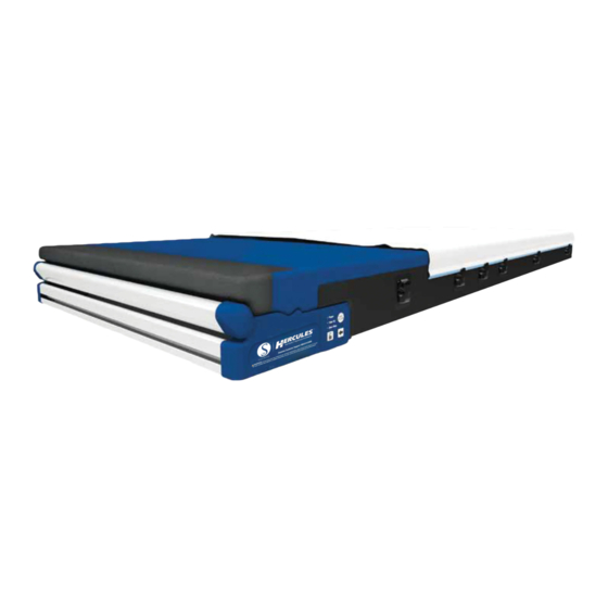
Unpacking and Set-Up Instructions Unpacking/Parts Breakdown Positioning Sheet Hercules Patient Repositioner Support Surface/Mattress Hercules Patient Repositioner Support Surface/Mattress Positioning Sheet... -
Page 8: Unpacking Instructions For The 39" Sw™ Lowboy®/Evolution
Unpacking Instructions for the 39” SW™ Lowboy®/Evolution™ Remove the products from the packing material and examine for shipping damage. If damage is detected in shipping, contact the freight company and file a damage complaint immediately. Included Items:... -
Page 9: Set-Up Instructions For The 39" Sw™ Lowboy®/Evolution
Set-Up Instructions for the 39” SW™ Lowboy®/Evolution™ NOTE: Read “Important Safety Instructions” prior to assembly/set-up. (See Table Of Contents) Tools Required: Follow these steps for installation on bedframes: 1. Remove headboard from bed and raise head of bed slight to access front edge of head section. - Page 10 3. Unplug the bed and any bed attached accessory outlet. 4. Place the Hercules Patient Repositioner box on bed. Open and fold back top of box. Gently flip unit onto open side. Pull box up to reveal contents. Gently lay the back down and...
- Page 11 5. Position the Hercules Patient Repositioner on top of the head section with the mounting holes facing the end of the bed. 6. Hook one of the bed brackets under the deck section of the bed. Lift the bed bracket up while pushing the bracket outward towards the transverse bar.
- Page 12 7. Repeat step 6 for the other bed bracket. 8. With the head of the bed 20 degrees, place the power cord in the slot between the head section and seat section of bed between the pivots of the sections. Feed the power cord through this opening.
- Page 13 9. Plug in bed. Raise head section of bed to its highest limit. Unplug bed. Route the power cord on top of middle frame tube with bed cables. Attach power cord to middle frame tube with wire tie close to the lift reaction plate. Do Not Tighten the Wire Tie At This Time.
- Page 14 10. This step is to ensure the power cord has proper slack. Plug in the bed. Lower the head section down to 10 degrees. Unplug the bed. Tighten wire tie placed in previous step.
- Page 15 11. Plug in the bed. Raise head section of the bed to its highest limit. Unplug the bed. Attach power cord to the middle frame tube with a wire tie in the approximate center length of the middle tube, close to the existing bed wire tie. Fully tighten wire tie. Attach the power cord to middle frame tube with a wire tie at the end of the middle frame tube, close to the existing bed wire tie.
- Page 16 12. Attach the power cord to middle frame tube with wire tie “C” at the end of the middle frame tube, close to the existing bed wire tie. Fully tighten wire tie.
- Page 17 13. Use wire ties “D” and “E” to connect the power cord to bed power cord on the outboard side of the bed strain relief. These wire ties should be placed approximately 2 inches from the strain relief and 4 inches apart. Trim all placed wire ties.
- Page 18 If pinching does exist, re-perform all appropriate steps to ensure proper installation. Ensure no patient entrapment risks exist between installed drive unit, sleep surface and the bed frame. Plug in the Hercules Patient Repositioner. If bed has scale, re-zero the scale. Please read the user manual prior to using product.
- Page 19 17. Pull the leading edge of the positioning sheet (the end containing buttonholes and “Advance Sheet” graphics) towards the head end of the bed. 18. Connect the positioning sheet to the sheet attachment strap by inserting the black caps into the buttonholes on each side at the head end of the sheet.
- Page 20 19. Secure the sheet by pulling the beaded hem into the sheet clips along both sides of the support surface starting at the foot end of bed and clip the sheet up toward the head section. Do not attach sheet to last clip on either side of support surface closest to head section. 20.
-
Page 21: Unpacking/Installation Instructions: Sw™ Bari-Rehab Platform
Unpacking/Installation Instructions: SW™ Bari-Rehab Platform 2™ Remove the products from the packing material and examine for shipping damage. If damage is detected in shipping, contact the freight company and file a damage complaint immediately. - Page 22 2™ Set-Up Instructions: SW™ Bari-Rehab Platform Tools Required: 1. Plug in bed. Remove headboard from bed and raise head of bed slightly to access front edge of the head section.
- Page 23 2. Unplug the bed and any bed-attached accessory outlet. 3. Remove the Hercules Patient Repositioner from its packaging. Place the Hercules Patient Repositioner on the top edge of the head deck with the mounting holes facing the end of bed.
- Page 24 5. Position one of the brackets so that the lip is located behind the head section cross tube. 6. Slide the bracket up so that the lip is located on the backside of the head section cross tube and the slots in the bracket line up with the third and fourth mounting holes (counting from the edge of the bed).
- Page 25 7. Attach the bracket to the Hercules Patient Repositioner using two of the four supplied screws. Do not fully tighten at this time. 8. Repeat steps four through six for the other bracket. Tighten all 4 screws.
- Page 26 9. Drop the power cord between the head section and seat section of the bed. 10. Plug in the bed. Raise the head section of the bed to its highest limit. Unplug the bed.
- Page 27 10. Cut existing wire tie that is located in the approximate middle of the wiring channel. 11. Using the hole that the removed wire tie utilized, attach the power cord into the wiring channel along with the existing bed cables with one of the 11” wire ties. Ensure the power cord has enough slack to not contact the head lift frame.
- Page 28 13. Following the bed cables, route the power cord under the cross brace. Secure the power cord to the bed power cord with the two 5.5” inch wire ties provided. Space the wire ties approximately two inches apart. These cable ties should be on the “wall” side of the P-clip.
- Page 29 17. For placement/installation of the Hercules Positioning Sheet, see the SW 39” Lowboy/Evolution set-up instructions step/number 16-20 and follow the procedure. (See Table of Contents) Ensure no patient entrapment risks exist between the patient and the installed Hercules Patient Repositioner System. Installation for this bed is complete.
-
Page 30: Operating Instructions
Control Unit Operation 1. Power LED: A green LED that is illuminated when the Hercules Patient Repositioner is connected to a power source. 2. Head Up LED: An amber LED that is illuminated when the head of the bed is raised past 30 degrees;... -
Page 31: Hercules Patient Repositioner
Controls are located on both sides of the Hercules Patient Repositioner, allowing for the operation of the system and providing status LEDs. 2. Mattress Attachment Hooks The two hooks located on the back wall of the Hercules Patient Repositioner are used to secure the support surface. 3. Drive Door The hinged drive door allows access to the roller compartment for cleaning and servicing purposes. - Page 32 Hercules Patient Repositioner Cont.
-
Page 33: Hercules Support Surface/Mattress
Hinged Head Section 2. The upper head section of the support surface is hinged, allowing it to be easily lifted by the user to access the Hercules Patient Repositioner. Mattress Attachment Straps 3. The straps, located on the bottom of the support surface, are used to secure it to the Hercules Patient Repositioner via the mattress attachment hooks. -
Page 34: Positioning Sheet
Positioning Sheet The Positioning Sheet is 46” wide by 16’ long and allows for approximately 8-10 positioning’s per use. Sheet Loading Indicator 1.The Load Indicator instructional markings (“Advance Sheet” graphics), located at the head end of the positioning sheet, indicate the distance and direction the sheet is to be advanced and how much sheet needs to be advanced into the drive unit prior to pulling patient weight. -
Page 35: Patient Care Functions
CPR, moving the person to the floor if possible. For performing CPR on the Hercules Patient Repositioner, place a CPR board lower the head of the bed, position the patient on their back and follow the standard CPR procedures of the facility. -
Page 36: Re-Positioning The Patient
Re-Positioning the Patient 1. Lower the head end of the bed to 30° or less and check that the amber Head Up and Door Open LEDs are not illuminated. 2. Press the “Unlock” button and the “Advance” button at the same time to advance the sheet. Release when the patient has reached the desired position. - Page 37 2. Pull the positioning sheet out of the Hercules Patient Repositioner and disconnect it from the sheet attachment strap. 3. Grasping each sheet clip, pull down to release the positioning sheet’s beaded hem on both sides of the support surface.
- Page 38 5. Unfold the positioning sheet along the side of the patient and place the remaining sheet at the foot end of the sleep surface. 6. Secure the positioning sheet to the side of the support surface you are working on by pulling the beaded hem into the sheet clips along that side of the support surface.
- Page 39 11. Press the “Unlock” button and the “Advance” button at the same time to advance the positioning sheet until the patient is in the desired position. 12. Place the remaining portion of the positioning sheet on the sheet shelf at the foot end of the support surface.
- Page 40 14. Press the “Sheet Release” button located on the user interface to disengage the roller and release the specialized sheet. The amber LED will illuminate. 15. Pull the positioning sheet out of the Hercules Patient Repositioner and disconnect it from the sheet attachment strap.
-
Page 41: Safety Tips
If the patient would have any clinical conditions that could result in risk of falling or improperly lying in bed, the bed should be left at its lowest setting and in flat position when not attended. Sizewise recommends the use of bed rails if they are available. There are seven zones of bed rail entrapment. -
Page 42: Storage And Disposal
Storage and Disposal Always store the support surface flat on a clean, level surface. Avoid storage of other equipment on top of the support surface. DO NOT expose the Hercules Patient Repositioner System to humidity greater than 95%. End-of-life Sizewise products must be disposed of properly according to local laws and... -
Page 43: Important Safety Instructions
Unplug the Hercules Patient Repositioner from the AC outlet before beginning any cleaning or service procedures. Failure to properly follow these instructions and facility protocol could result in serious injury, death or equipment damage. -
Page 44: Support Surface Cleaning Safety Instructions
Please ensure the positioning sheet is properly secured in the sheet clips initial patient repositioning. When first making the bed using the Hercules Patient Repositioner System, the positioning sheet should be advanced until the “Advance Sheet” graphics are completely beyond the head end edge of the support surface. - Page 45 The safe working load of the Hercules Patient Repositioner System is 340 kg (750 lbs). Failure to stay at or below this limit may cause equipment damage. See specifications for protection against fluid ingress. Failure to do so may cause equipment damage.
-
Page 46: Cleaning Instructions
7. Do not use excessive liquid or harsh cleaning agents. Do not power wash. Do not steam clean. 8. Do not use hard surface cleaners or solvents not intended for fabric applications. 9. The following cleaners/disinfectants have been approved to work with the SW Hercules™ Sleep Surface: Dispatch™, Clorox Healthcare Bleach™, and PRO-TECH™... -
Page 47: Cleaning The Hercules Patient Repositioner
2. With the positioning sheet removed, lift the hinged head section of the support surface to expose the system’s drive door. 3. Open the door and wipe down all exposed surfaces of the Hercules Patient Repositioner and the sheet attachment strap using a soft sponge or cloth with mild detergent and warm water. -
Page 48: Positioning Sheet Laundry Instructions
Positioning Sheet Laundry Instructions The Positioning Sheet is comprised of 100% lint-free polyester fibers and is treated to encourage antimicrobial and soil release activity to ensure long lasting use. The following laundering procedures are recommended: We recommend a low active alkalinity wash solution and thorough rinsing and neutralization to remove surfactants and residual alkali. -
Page 49: Maintenance
If any of the items are loose, worn, bent or distorted immediately have them checked and/or repaired by an authorized Sizewise technician. Frequent maintenance and servicing will improve performance and extend mattress life. For long term use, the following maintenance chart should... -
Page 50: Troubleshooting
Check to ensure that the positioning sheet is properly attached to all of the sheet clips. If there is power loss: Check the ON/OFF switch. Check power cord for any damage. NOTE: If the troubleshooting process does not solve the problem please contact a Sizewise representative for service. -
Page 51: Service Instructions
Remove the Hercules Patient Repositioner from the bed. Rest the new Hercules Patient Repositioner on its face at the head end edge of the bed. Attach the power cord to the Hercules Patient Repositioner by inserting the plug into the receptacle and securing the new P-clip. -
Page 52: Power Cord Replacement
2. Repeat step 1 for the mattress attachment strap on the opposite side of the support surface. 3. Detach the Hercules Patient Repositioner from the bed by removing the four screws in the attachment brackets located on the front face of the drive unit adjacent to the headboard. -
Page 53: Sheet Attachment Strap Replacement
Sheet Attachment Strap Replacement Tools Required: Philips screwdriver 1. Pull the sheet attachment strap out of the Hercules Patient Repositioner so that the three clasps are exposed that secure the sheet attachment strap to the drive unit’s roller. Using a standard Philips screwdriver, remove the three screws that attach the clasps to the roller. -
Page 54: Frequently Ordered Parts
Frequently Ordered Parts Power Supply………………………………………………………………….…………27607000 Control PCB………………………………………………………………………….…..27607001 Motor/Clutch Assembly………………………………………………………………….27607002 Left User Interface Control…………………………………………………………...….27607003 Right User Interface Control…………………………………………………………..27607004 Power Cord 13.5” (34.2 cm)………………………..…………………………………..27000445 Sheet Strap……………………………………………………………………………….27607005 Obtaining Parts and Service For parts and service information contact your Sizewise Representative at 1-800-814-9389. -
Page 55: Warranty Information
90 Day Limited Warranty: Top Cover Sizewise warrants, to the original purchaser, if within the first 90 days from the date of purchase, a defect is found in material or workmanship; we will inspect and repair or replace the product at no charge. -
Page 56: User Assistance Information
User Assistance Information For questions or assistance with this product, contact Sizewise at: Sizewise 1600 Genessee Suite 950 Kansas City, Missouri 64102 Phone: 1-800-814-9389... - Page 57 Kansas City, Missouri 64102 Phone: 1-800-814-9389 sizewise.net Sizewise and Sizewise Rentals are trademarks of Sizewise Rentals, L.L.C. All specifications, equipment and prices are subject to change without notice. Photos and drawings are representative of the products and may vary slightly from actual production models.
Need help?
Do you have a question about the Hercules and is the answer not in the manual?
Questions and answers
How to obtain a weight using the Hercules bed?