
Subscribe to Our Youtube Channel
Related Manuals for Sizewise Alliance


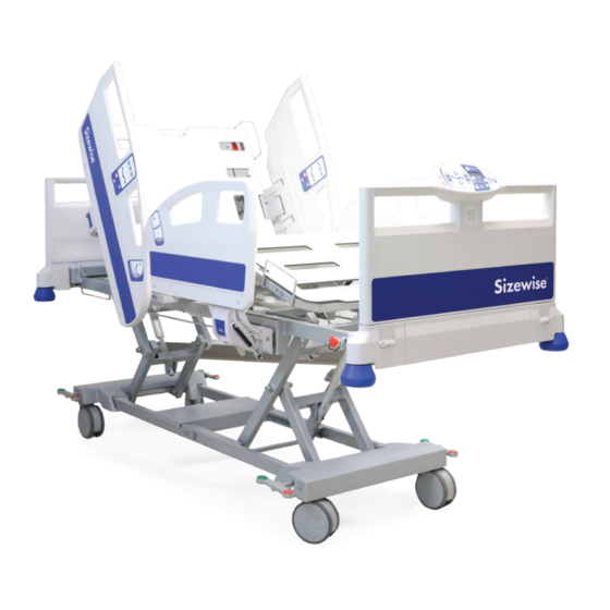
Summary of Contents for Sizewise Alliance
- Page 1 Sizewise Alliance™ User Manual Doc. #8110, Rev. 5.0, Rev. Date: 2/26/2021 MFG-0020A-0619...
-
Page 2: Table Of Contents
Scale System: Adding/Removing Items ..................21 Scale System: Weight History Time Setting ................21 Protocol: Set Alert Reminder....................22 Protocol Timer: Sound Level Setting..................22 Setting the Time/Date......................23 Operating Instructions........................24 Alliance™ Operating Instructions ...................24 Foot Controls ..........................24 Hand Control...........................25 Operation of Bed........................26 Wiring Diagram........................28... - Page 3 Controls………………………………………………………………………………….…..29 Head Side Rail Contro…......………….……………..…………….…….…29 Operation of Controls …………….………………………………………………….……30 Bed Exit Alarm........................33 Scale System...........................35 Protocol Timer........................36 Bed Exit Alarm: Alert Tones ....................37 Bed Exit Alarm: Record Message..................37 Scale System: Weight Adjustm....................38 Scale System: lbs/ kgs Setting....................38 Scale System: Locking/Unlocking Unit in lbs/kgs..............39 Proper Use.............................40 Reaching or Leaning........................40 Side Rails ..........................41...
- Page 4 Maintenance............................63 Fasteners.............................64 Storage and Disposal......................... 66 Troubleshooting ..........................67 RSS Troubleshooting.........................69 Limited Product Warranty ......................70 Manufacturer Disclaimer ......................72 User Assistance Information .......................73...
-
Page 5: Definition Of Symbols
Ensure proper clearance between footboard and patient Incompatible mattresses can create hazards. Read instructions for use” Only use siderails designed for the Sizewise Alliance bed When routing cables from other equipment in the MEDICAL BED, precautions taken to avoid squeezing those between parts of the MEDICAL BED Warning against crushing. -
Page 6: Warnings And Cautions
For user and patient safety, read and follow all warnings and instructions that apply to use of Alliance™ and Rest Secure System™ (RSS). Before using this bed, the user must know what to do to ensure safety. Put the patient at ease. The caregiver should ensure the patient understands procedures. -
Page 7: Symbols And Labels
Symbols and Labels Symbols, definitions, and fonts are used throughout this manual to aid user readability and understanding of content. Standard Text Used for regular information. Bold Text Emphasizes a word or phrase. NOTE Sets apart special information or important instruction clarification. Safe Working Load The equipment’s maximum external mechanical load permitted in normal use. - Page 8 Located on bed frame. Patient Size for Adults: Physical description of an adult. Alliance™ Series Safe Working Load: Graphic symbol for maximum patient weight and safe working load. 408 lbs. / 185 kg 550 lbs.
- Page 9 Symbols and Labels Label Definition CPR: Graphic symbol for CPR Position. Hip Positioning: Graphic symbol for position of patient hips. Danger: Pinch Point: Marking to signify pinch point danger area. Lock Casters: Marking to direct locking brake casters before operation. Minimal Clearance Area: Marking to caution areas required to be free from obstructions.
-
Page 10: Important Safety Instructions
• To lessen the possibility of electric shock when plugging the RSS into the wall outlet, use ONLY grounded or hospital-grade outlets. • DO NOT use Alliance™ or RSS if the power cord is cut, frayed or loosely connected to the bed. - Page 11 • Before positioning patient on bed, verify all components are secure after adjustments, repairs, or servicing of the trapeze, single pole patient assist, or any other overhead components/devices. • Use only parts, accessories and adapters authorized by Sizewise.
- Page 12 • Only use Sizewise Alliance specific parts for replacement or repairs. The use of improper replacement parts could result in patient and/or user injury as well as damage to equipment or other property.
-
Page 13: Device Information
Device Information Description of Alliance™ is designed for use in hospitals, clinics and other related uses. It is designed to give a useful life of 10 to 15 years depending on usage. Features include a steel structure with a polycarbonate-covered surface. -
Page 14: General Bed Components
CPR Release General Bed Components NOTE: Not shown: Power Interface Box, Foot Junction Box, 6 Volt, Lead Acid Battery and Nurse Call Interface. RSS Description The purpose of the RSS is to alert the caregiver that a patient is attempting to exit the bed or is at an immediate risk of falling in settings where continuous surveillance of a patient is not possible. -
Page 15: Specifications
Specifications Alliance™ Specifications …………………………..IEC 60601-2-52:2009 Ed. 1+C1: A1 Quality Assurance Standard .......IEC 60601-1-6:2010 Ed.3 +A1 ……………………………………….. IEC 60601-1:2005 Ed.3+A1] ………………………………………CSA C22.2#60601-1:2014 Ed.3] ……………………... AAMI ES60601-1:2005 +A1 Degree of Protection Against Electric Shock.............Type B Degree of Protection Against Ingress of Water..............IPX4 Electrical Rating................100 - 240 VAC, 50/60 Hz, 5A... -
Page 16: Rss Specifications
RSS Specifications Control Box Housing Material ....................ABS, UL94-V0 rated Width........................5.79”/14.7 cm Length ........................3.16”/8 cm Height ……......................2.08”/5.3 cm Connectors DC Power Input................5.5mmx2.1mm coaxial Load Cell.......................4 x RJ12 shielded Nurse Call ................Two relay outlets (dual priority) USB Debug/FW Update………………………………………………………..…USB Port Nurse Call Open.......................... -
Page 17: Hand Control
WARNING: Any change to the specifications can result in malfunction or damage to the RSS. Footboard Control with Integrated RSS System This Control is located inside the footboard. Operating Current Normal........................54-160 mA Alarming........................150 mA Audio Record Memory.......................4 Mb Voice Record Alarm Time..................15 seconds Sound Level....................90 dB @ 12 inches Tones....................5 user selectable tones Display... -
Page 18: Unpacking And Setup Instructions
Unpacking and Setup Instructions The principal components of the Alliance™ Unpacking/Parts Breakdown Unpacking Instructions: Remove the products from the packing material and examine for shipping damage. If damage is detected in shipping, contact the freight company and file a damage complaint immediately. -
Page 19: Rss Setup
RSS Setup Basic Setup DO NOT use the RSS if the power cord is cut, frayed or loosely connected to the bed. The Nurse Call Interface cable at the head of the bed should be securely plugged into the Nurse Call Interface on the wall to function properly. -
Page 20: Bed Exit Alarm: Alert Type
Bed Exit Alarm: Alert Type The nurse call is always active no matter what selection is made. When selecting nurse call only, the audio alert will be disabled at the bedside. An alarm will sound if a voice message has not been recorded and the unit is set to Voice Recording. -
Page 21: Scale System: Adding/Removing Items
Scale System: Adding/Removing Items The feature will allow items such as blankets or pillows to be added and removed from the bed without affecting the current weight reading of a patient. 1. Access the Menu by pressing the Up or Down arrow until ADD/REMOVE ITEMS is highlighted and press Enter. -
Page 22: Protocol: Set Alert Reminder
Protocol: Set Alert Reminder The protocol reminder is a timer that can be set for 1, 2, or 4 hours as a reminder that the patient needs to be attended to or checked on. There are three alert settings for the protocol alarm. 1. -
Page 23: Setting The Time/Date
Setting the Time/Date 1. Access the Menu by pressing the Up or Down arrow until SYSTEM SETTINGS is highlighted and press Enter. 2. Select SET TIME/DATE and press Enter. 3. Using the Up or Down arrow, set the hours and press Enter. The time must be set in 24-hour clock.(13:00 = 1:00 pm) 4. -
Page 24: Operating Instructions
Operating Instructions Alliance™ Operating Instructions Footboard Controls The footboard controls are located at the foot end of the bed. The controls have individual lockout functions as well as a master lockout switch. Locking out the specific function or all functions will disable the function on both hand and foot controls. If a button is pushed while the function is locked out, a light will show for notification that an unauthorized operation has been selected. -
Page 25: Hand Control
Hand Control These instructions are for the general functions of the bed; any special or unique functions will be referenced within different sections of this manual. Make sure that the bed is correctly positioned and connected to a properly grounded hospital- grade outlet. -
Page 26: Operation Of Bed
Operation of Bed The operation of the bed is divided into two subsystems: Electrical and Mechanical. Item Description Item Description Removable Headboard Locking Mechanism Rail with Membranes Removable Footboard Mattress Platform Modules Multifunction Pedal Extendable Lever WARNING: Failure to heed the warnings pertaining to the operation of the bed could result in patient and/or caregiver injury, as well as damage to equipment or other property. - Page 27 Item Description Removable headboard CPR Lever Rail with membrane Control Box Linear Actuator Backrest Linear Actuator Lifting Linear Actuator Lifting Linear Actuator Legs Battery Under Bed Light (blue in color)
-
Page 28: Wiring Diagram
Wiring Diagram • System Control Box • Battery. • Two connection boxes with light (depending on variants). • Four linear actuators (one for backrest, one for legs, and two for lifting). • Two rails with membrane controls. • Patient control. •... -
Page 29: Controls
Controls PATIENT AND NURSE HEAD SIDE RAIL CONTROL Item Description Item Description Raise Backrest Lower Legs Lower Backrest Lock Indicator Raise Mattress Platform Nurse Call Under Bed Light (blue in color) Lower Mattress Platform Raise Legs Low Position Indicator NOTE: The patient and nurse control is located on the left and right head side rails. -
Page 30: Operation Of Controls
Operation of Controls Raise or Lower Backrest By way of the Raise or Lower Backrest buttons, the backrest module can be tilted into the desired position. Refer to the Table of Contents – Specifications section for the maximum and minimum tilt information. To activate the movement, hold down the Raise or Lower Backrest button to move the backrest into the maximum or minimum tilt respectively. - Page 31 Raise or Lower Backrest and Legs Simultaneously By way of the Raise or Lower Backrest and Legs Simultaneously buttons, both modules can be tilted into the desired position at the same time. Refer to the Table of Contents – Specifications section for the maximum and minimum tilt information.
- Page 32 Trendelenburg/Reverse Trendelenburg By way of the Trendelenburg and Reverse Trendelenburg function, the bed can be tilted by a maximum of 12° in the Trend movement and 12° in the Reverse Trend movement. Reverse Trendelenburg Activation: Press the Reverse Trend button to tilt the headboard with respect to the footboard up to a maximum tilt of 12°.
-
Page 33: Bed Exit Alarm
Under Bed Light Button By way of the Under-Bed Light button, a light is switched on under the mattress platform, allowing patients to walk around at night without the need to switch on the main light and without disturbing others. To activate the light, press the button once. - Page 34 WARNING: The bed is to be used in accordance with each facility’s policies and procedures. There are 3 bed exit alarm sensitivity settings: High Sensitivity: Detects patient movement; typically this setting would be used by the caregiver when needing to be notified of any movement, generally for patients at very high risk for falls.
-
Page 35: Scale System
Scale System: Use Scale and Access Weight History The RSS’s integrated scale helps reduce the risk of caregiver or patient injury by allowing caregivers to accurately record the patient weight without having to transport or move the patient each time the weight is needed. The scale system is set to weigh and record the patient weight automatically at midnight every day up to 30 days. -
Page 36: Protocol Timer
Protocol Timer: Using the Timer The RSS protocol timer can be utilized to alert the caregiver that the patient needs to be attended to or checked on at intervals of 1, 2 or 4 hours. The protocol timer, has the capability to alerts the caregiver with an audible tone on the unit and, if connected to the Nurse Call Interface, can activate the nurse call signal. -
Page 37: Bed Exit Alarm: Alert Tones
Bed Exit Alarm: Set Alert Tones There are 5 different audible tones for the bed exit alarm. The user will hear each of the different tones as they scroll through the 5 selections. 1. Access the Menu by pressing the Up or Down arrow until Bed Exit Settings is highlighted and press Enter. -
Page 38: Scale System: Weight Adjustm
Scale System: Adjust Weight This feature is designed to manually adjust the weight if items were added to the bed without using the Add/Remove option. The caregiver will need to know the patient's weight before using this option. 1. Access the menu by pressing the Up or Down arrows until SCALE SETTINGS is highlighted and press Enter. -
Page 39: Scale System: Locking/Unlocking Unit In Lbs/Kgs
Scale System: Locking/Unlocking the Unit in Lbs./Kgs. As part of a safety feature, this unit has the ability to lock the unit of measure in lbs. or kgs. This will prevent accidently changing the units in the Scale Settings menu. 1. -
Page 40: Proper Use
Proper Use of the Bed WARNING: Follow the instructions for assisting patients in and out of the bed to avoid a fall or injury to the patient and/or caregiver. To get in the bed, follow these steps for proper positioning height: 1. -
Page 41: Side Rails
Side Rails RAISING THE RAIL To raise the rail, pull the rail upwards to its highest position until it locks in place. When the rail is raised, make sure it is totally locked, as damage may be caused if it is lowered accidentally. -
Page 42: Seven Zones Of Bed Rail Entrapment
If the patient would have any clinical conditions that could result in risk of falling or improperly lying in bed, the bed should be left at its lowest setting and in flat position when not attended. Sizewise recommends the use of bed rails if they are available. There are seven zones of bed rail entrapment. - Page 43 Seven Zones of Bed Rail Entrapment WARNING: Bed rail entrapment can result in serious injury or even death. Sizewise recommends caregivers be mindful of the FDA guidelines relevant to bed rail entrapment. These guidelines can be found on the FDA website as referenced below.
- Page 44 Seven Zones of Bed Rail Entrapment This bed complies with IEC 60601-2-52 standard for bed rail entrapment. Below are the specifications of that standard. DESIGNATOR DESCRIPTION DIMENSION Smallest dimension between elements inside ≤ 120 mm the perimeter of the SIDE RAIL in its raised/locked positions or perimeters created between the SIDE RAIL and fixed parts of the BED.
-
Page 45: Cpr Release System And Transfers
CPR RELEASE SYSTEM Operate the lever located below the backrest, in turn accompanying the module as it lowers. For the safety of the patient, the system includes a damper to prevent the backrest from abruptly falling back . There is a risk of trapping or crushing as the moving parts of the bed's mattress platform are lowered. -
Page 46: Features
Features Casters Lock and Steer There is one lock and steer caster located on the right foot of the bed. When the green pedal is pressed down, the caster will lock, prohibiting swivel but allowing for bed maneuvering. This makes it the steering caster. Press down on the green pedal to engage the steer caster and lift up on the pedal to unlock. -
Page 47: Connection Of Electrical Components
RSS Connections... -
Page 48: Emergency Battery Backup
Emergency Battery Backup In case of power failure the emergency battery backup will operate the bed. Use only in emergency situations, as battery backup is not designed for continuous use. The battery will recharge itself while the bed is plugged into a hospital-grade or grounded outlet. It takes 24 hours to fully charge/recharge the battery backup. -
Page 49: Serial Number Location
Serial Number Location The bed has a manufacturer number and a serial number. The serial numbers are located at the head of the bed. Manufacturer Serial Number IV Pole The IV pole can be placed in any of the four accessory attachment points on the bed. -
Page 50: Trapeze Assembly
User Manual, Technical Manual, and Work Instructions. If you do not understand these instructions, or documents referenced, contact Sizewise at 1-800-814-9389. WARNING: Do not attempt to install, repair, or remove the trapeze, single pole patient assist, or any other overhead components/devices while bed is occupied. -
Page 51: Safety Tips
WARNING: Portable RF communications equipment (including peripherals such as antenna cables and external antennas) should be used no closer than 30 cm (12 in) to any part of the Alliance™ control unit, including cables specified by the manufacturer. Otherwise, degradation of the performance of this equipment could result. - Page 52 At 0˚, 45˚, 90˚, 135˚, 180˚, 225˚, Mains power quality should be that 270˚, and 315˚ 270˚, and 315˚ of a typical commercial or hospital Voltage Dips environment. If the user of Alliance™ 0% U : 1 cycle 0% U : 1 cycle and Short requires continued operation during At 0˚...
- Page 53 RF transmitters, an electromagnetic site survey should be considered. If the measured field strength in the location in which Alliance™ is used exceeds the applicable RF compliance level above, the control unit should be observed to verify normal operation.
- Page 54 Immunity to Proximity Fields from Radio Frequency Wireless Communications Equipment In addition to the Radiated RF IEC 61000-4-3 as shown in the table above, Alliance™ has been tested as specified in the table below. Test Immunity Maximum Frequency Band (MHz)
-
Page 55: General Safety
General Safety WARNING: The bed is to be used in accordance with each facility’s policies and procedures. CAUTION: Possible fire hazard when used with oxygen- administering equipment other than the nasal mask or 1/2 bed length type tent. Oxygen tent should not extend below the mattress support level. Lock hand control at foot of bed when using oxygen administering equipment. -
Page 56: Transport
Transport WARNING: Use caution during transport, so th e be d do e s no t tip or overbalance. Failure to do so could result in patient and/or user injury as well as damage to equipment or other property. CAUTION: The bed needs to be transported and stored in a temperature range of 5°C to 40°C (41°F to 104°F). -
Page 57: Cleaning Instructions
Cleaning Instructions WARNING: Before cleaning the bed, be sure to disconnect it from the wall outlet (power source). Failure to do so could result in electrical shock and could result in patient and/or user injury, as well as damage to equipment or other property. - Page 58 General Patient Room Cleaning/Disinfecting Personal Protective Equipment (PPE) should always be used as directed by the Safety Data Sheet for the disinfectant. Prepare the disinfectant according to the manufacturer’s recommendations. Prepare a separate bucket of warm, fresh water to be used for rinsing the equipment after cleaning/disinfecting procedures are completed as instructed.
- Page 59 Steam Cleaning This product may be steam-cleaned to eliminate bacteria and/or bed bug infestations, if desired. When applying steam, avoid areas such as electrical connections and components including RSS, hand and/or footboard controls that may be damaged by being exposed to excessive moisture and/or heat.
- Page 60 Sleep Surfaces (Including Mattress Bases and Top Covers) NOTE: The use of bleach-based products/solutions will provide a higher concentration of the agent than is required to eliminate the bacteria and will increase the potential for damage to the fabric, and the built-in protective barrier of the sleep surface. NOTE: To reduce the discoloration of the sleep surface lining, surfaces must be thoroughly rinsed with clean, fresh water to remove chemical residues immediately after the required “wet contact time”...
- Page 61 Control unit air filters must be cleaned weekly. Replacement of the control unit air filter is recommended every 6 months. 1. Remove the air filter located on the back of the control unit. 2. Clean with prepared disinfectant solution and allow to air dry. 3.
- Page 62 Accessories: Patient Assist Bar ‐ 27003802 4 Point IV Pole ‐ 27000465 X‐Ray Cassette Holder ‐ 27003900...
-
Page 63: Maintenance
Check the items on this chart at the indicated intervals. If any of the items are loose, worn, bent or distorted, immediately have them checked and/or repaired by an authorized Sizewise Technician. Frequent maintenance and servicing will improve performance between each use and extend bed life. -
Page 64: Fasteners
If a problem is detected, make sure to repair or adjust the bed before using it. Contact an authorized Sizewise technician to help find and correct the problem. Fasteners WARNING: Many of the screws and bolts used in the bed are special high-strength fasteners. - Page 65 Patient Control Visually check that the control connector is in good condition. Check that the cable is in good condition. Check that the buttons are in good working order. Select each movement made by the control for two seconds. It must perform the function chosen and the movement should be continuous.
-
Page 66: Storage And Disposal
5°C to 40°C (41°F to 104°F). DO NOT expose the bed to humidity greater than 95%. End-of life Sizewise products must be disposed of properly according to local laws and regulations. If your product contains a battery and/or electronic components, disposal of those components must be completed separate from standard waste disposal. -
Page 67: Troubleshooting
24 hours. • Ensure all cables to the Electronic Control Module are properly connected and secure. NOTE: If the troubleshooting process does not solve the problem, please contact a Sizewise representative for service. Problem Solution Unlock the function(s) by following these steps: The bed has some functions locked. - Page 68 There might be a problem in the connection After resetting the system, the bed works BUT cables which this problem can cause a short if any button is pressed the bed will lock circuit in the control box . again. Contact Technical Support.
-
Page 69: Rss Troubleshooting
RSS Troubleshooting CAUTION: Only authorized personnel should engage in the troubleshooting process. Troubleshooting by unauthorized persons could result in personal injury or equipment damage. Display on footboard shows Load Cell Error or red light flashing on the RSS under the bed: •... -
Page 70: Limited Product Warranty
Alliance user manual in effect at the time of sale of the product, including without limitation the safety instructions and if applicable the safe working load and weight limitations set forth therein. - Page 71 If Sizewise determines the problem with the product or part(s) is a result of defective material or workmanship, the product or part will be replaced or repaired at the discretion of Sizewise, and at no charge to the Buyer; however, this is subject to the limitations and exclusions of this Limited Product Warranty.
-
Page 72: Manufacturer Disclaimer
15. Products or items not manufactured by Sizewise. Rather, for products or items obtained by Sizewise from an original manufacturer or third party supplier, Sizewise may assign to the Buyer any warranty rights in such products or items that Sizewise may have from the original manufacturer or third party supplier, to the extent such assignment is allowed by the original manufacturer or third party supplier. -
Page 73: User Assistance Information
(3) refund of the purchase price. Sizewise Limited P r o d u c t Warranty service may be obtained by contacting Sizewise or the authorized dealer from whom Buyer purchased the item. Sizewise compensates only Sizewise -authorized service providers for warranty trips within their normal service area to repair commercial products at the customer’s location. - Page 74 Lenexa, KS 66215 800-814-9389 sizewise.com Sizewise is a registered trademark of Sizewise Rentals, LLC. All specifications, equipment, and prices are subject to change without notice. Photos and drawings are representative of the products and may vary slightly from actual production models.
Need help?
Do you have a question about the Alliance and is the answer not in the manual?
Questions and answers
BED ALARM GOES OFF, WILL NOT TURN OFF
To turn off the bed alarm on a Sizewise Alliance, follow these steps:
1. Access the Menu by pressing the Up or Down arrow until BED EXIT SETTINGS is highlighted, then press Enter.
2. Select SET ALERT TYPE and press Enter.
3. Choose Off from the available alert types and press Enter.
4. The selection will take you back to the home screen, confirming the alarm is off.
This answer is automatically generated