Table of Contents
Advertisement
Quick Links
www.ti.com
User's Guide
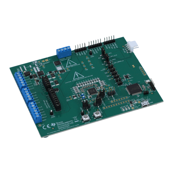
BQ76952 Evaluation Module
Matt Sunna
The BQ76952EVM evaluation module (EVM) is a complete evaluation system for the BQ76952, a 3-cell to 16-
cell Li-Ion battery monitor integrated circuit. The EVM consists of a BQ76952 circuit module which is used for
simple evaluation of the BQ76952 monitor function. The circuit module includes one BQ76952 integrated circuit
(IC), sense resistor, thermistors, power FETs, and all other onboard components necessary to protect the cells
from overcharge, over discharge, short circuit, overcurrent discharge, over temperature and under temperature
in a 16-series cell Li-Ion or Li-Polymer battery pack. The circuit module connects directly across the cells in a
battery, or can be connected with a power supply and the included cell simulator resistors. With the on-board
interface or compatible external interface board and Microsoft
(GUI) software, the user can view the device registers, evaluate voltage, current and temperature accuracy,
perform calibration, adjust protection limits and enable FET control outputs.
space
1
Features...................................................................................................................................................................................3
Contents........................................................................................................................................................................3
1.2 Ordering Information..........................................................................................................................................................
1.4 Required Equipment..........................................................................................................................................................
2 BQ76952 EVM Quick Start Guide..........................................................................................................................................
2.1 Before You Begin...............................................................................................................................................................
Start..........................................................................................................................................................................5
3 Battery Management Studio Software..................................................................................................................................
Requirements........................................................................................................................................................7
BQStudio.............................................................................................................................................................7
3.3 BQ769x2 bqz File Installation............................................................................................................................................
3.4 BQStudio Operation and Registers View...........................................................................................................................
3.5 Commands.......................................................................................................................................................................
3.6 Data Memory....................................................................................................................................................................
3.7 Calibration........................................................................................................................................................................
Sequences......................................................................................................................................................15
Simulator...................................................................................................................................................................17
4.2 Evaluating with Load Current...........................................................................................................................................
4.4 Evaluating with Simulated Current...................................................................................................................................
4.5 Reducing the Cell Count..................................................................................................................................................
4.6 Connecting Cells..............................................................................................................................................................
Host........................................................................................................................................................21
4.8 Hardware Configuration...................................................................................................................................................
Layout....................................................................................................................................................................24
Materials.................................................................................................................................................................32
Compliance.........................................................................................................................................................39
SLUUC33A - NOVEMBER 2019 - REVISED OCTOBER 2020
Submit Document Feedback
ABSTRACT
Table of Contents
Use...............................................................................................................................................17
Currents.....................................................................................................................17
Programming...............................................................................................................................23
Construction........................................................................................................24
Copyright © 2020 Texas Instruments Incorporated
®
Windows
®
based PC graphical user interface
Summary.........................................................................................3
Table of Contents
3
3
4
4
7
7
7
11
11
13
17
18
19
20
22
BQ76952 Evaluation Module
1
Advertisement
Table of Contents

Related Manuals for Texas Instruments BQ76952EVM


Summary of Contents for Texas Instruments BQ76952EVM
-
Page 1: Table Of Contents
Matt Sunna ABSTRACT The BQ76952EVM evaluation module (EVM) is a complete evaluation system for the BQ76952, a 3-cell to 16- cell Li-Ion battery monitor integrated circuit. The EVM consists of a BQ76952 circuit module which is used for simple evaluation of the BQ76952 monitor function. The circuit module includes one BQ76952 integrated circuit... - Page 2 ® and Windows ® are registered trademarks of Microsoft Corporation. All other trademarks are the property of their respective owners. BQ76952 Evaluation Module SLUUC33A – NOVEMBER 2019 – REVISED OCTOBER 2020 Submit Document Feedback Copyright © 2020 Texas Instruments Incorporated...
-
Page 3: Features
• Electronic load or assorted resistors Additional equipment may be desired to operate the BQ76952 with a more extensive demonstration. SLUUC33A – NOVEMBER 2019 – REVISED OCTOBER 2020 BQ76952 Evaluation Module Submit Document Feedback Copyright © 2020 Texas Instruments Incorporated... -
Page 4: Bq76952 Evm Quick Start Guide
Warning The bq76952EVM is not rated as a high voltage EVM, has smaller clearances than normally used on high voltage boards and does not have an isolation boundary. If you apply high voltage to this board, all terminals should be considered high voltage. -
Page 5: Quick Start
15.When complete with this quick start demonstration, exit the BQStudio software and turn off the power supply. Refer to other sections of this user guide for additional details. SLUUC33A – NOVEMBER 2019 – REVISED OCTOBER 2020 BQ76952 Evaluation Module Submit Document Feedback Copyright © 2020 Texas Instruments Incorporated... -
Page 6: Figure 2-1. Evm Connection For Basic Operation
DC Power Supply Position shunts Install cell to uC_SCL and simulator shunts uC_SDA Figure 2-1. EVM Connection for Basic Operation BQ76952 Evaluation Module SLUUC33A – NOVEMBER 2019 – REVISED OCTOBER 2020 Submit Document Feedback Copyright © 2020 Texas Instruments Incorporated... -
Page 7: Battery Management Studio Software
Proceed? window which must be acknowledged. If the software still can not find the device, a Battery Management Studio popup window appears indicating communication status. Acknowledge the message to proceed. SLUUC33A – NOVEMBER 2019 – REVISED OCTOBER 2020 BQ76952 Evaluation Module Submit Document Feedback Copyright © 2020 Texas Instruments Incorporated... -
Page 8: Figure 3-1. Target Selection Wizard
The tool tip closes after approximately 30 seconds. To avoid the tool tip display move the cursor to the value or units column, or to the Dashboard pane. BQ76952 Evaluation Module SLUUC33A – NOVEMBER 2019 – REVISED OCTOBER 2020 Submit Document Feedback Copyright © 2020 Texas Instruments Incorporated... -
Page 9: Figure 3-2. Bqstudio Window Without Device
If a device is connected and powered after BQStudio is powered, dashboard may auto detect the device and update the device and register display. Figure 3-3 shows a register display with a connected device. SLUUC33A – NOVEMBER 2019 – REVISED OCTOBER 2020 BQ76952 Evaluation Module Submit Document Feedback Copyright © 2020 Texas Instruments Incorporated... -
Page 10: Figure 3-3. Register View With Device
These tabs can be closed with the "X" as desired, but closing the tab may terminate the operation running in the tab. Figure 3-4. Tool Selections BQ76952 Evaluation Module SLUUC33A – NOVEMBER 2019 – REVISED OCTOBER 2020 Submit Document Feedback Copyright © 2020 Texas Instruments Incorporated... -
Page 11: Commands
Data Memory must be written after bit changes, a button is provided under the bit SLUUC33A – NOVEMBER 2019 – REVISED OCTOBER 2020 BQ76952 Evaluation Module Submit Document Feedback Copyright © 2020 Texas Instruments Incorporated... -
Page 12: Figure 3-6. Data Memory Bit Field Change
6. Select the Program Data Memory to OTP Memory button. If successful, the display is similar to the check. 7. Adjust the board voltage back to normal operating conditions, cycle power, and test as desired. BQ76952 Evaluation Module SLUUC33A – NOVEMBER 2019 – REVISED OCTOBER 2020 Submit Document Feedback Copyright © 2020 Texas Instruments Incorporated... -
Page 13: Calibration
Measuring each cell voltage value is recommended rather than using a common value if individual cell voltage calibration is desired. SLUUC33A – NOVEMBER 2019 – REVISED OCTOBER 2020 BQ76952 Evaluation Module Submit Document Feedback Copyright © 2020 Texas Instruments Incorporated... -
Page 14: Figure 3-8. Calibration View
Battery Management Studio Software www.ti.com Figure 3-8. Calibration View BQ76952 Evaluation Module SLUUC33A – NOVEMBER 2019 – REVISED OCTOBER 2020 Submit Document Feedback Copyright © 2020 Texas Instruments Incorporated... -
Page 15: Command Sequences
Command Sequence File Assignment Buttons section. Results can be viewed in the Transaction Log and saved to a file if desired. SLUUC33A – NOVEMBER 2019 – REVISED OCTOBER 2020 BQ76952 Evaluation Module Submit Document Feedback Copyright © 2020 Texas Instruments Incorporated... -
Page 16: Figure 3-11. Command Sequence View
Battery Management Studio Software www.ti.com Figure 3-11. Command Sequence View BQ76952 Evaluation Module SLUUC33A – NOVEMBER 2019 – REVISED OCTOBER 2020 Submit Document Feedback Copyright © 2020 Texas Instruments Incorporated... -
Page 17: Bq76952 Circuit Module Use
Be sure to set the supplies appropriately to prevent exceeding the ratings of the EVM. SLUUC33A – NOVEMBER 2019 – REVISED OCTOBER 2020 BQ76952 Evaluation Module Submit Document Feedback Copyright © 2020 Texas Instruments Incorporated... -
Page 18: Evaluating With Simulated Current
Polarity can be reversed on the load supply to simulate a charge current. The battery simulation supply must never be reversed. BQ76952 Evaluation Module SLUUC33A – NOVEMBER 2019 – REVISED OCTOBER 2020 Submit Document Feedback Copyright © 2020 Texas Instruments Incorporated... -
Page 19: Reducing The Cell Count
0 ohm Cell 1) Cell 15 CELL15 to CELL14 VC15 to VC14 Cell 14 CELL14 to CELL13 VC14 to VC13 SLUUC33A – NOVEMBER 2019 – REVISED OCTOBER 2020 BQ76952 Evaluation Module Submit Document Feedback Copyright © 2020 Texas Instruments Incorporated... -
Page 20: Connecting Cells
3. Be sure the cell simulator shunts are removed Figure 4-5 shows an example connecting cells with an EVM configuration reduced to 15 cells. BQ76952 Evaluation Module SLUUC33A – NOVEMBER 2019 – REVISED OCTOBER 2020 Submit Document Feedback Copyright © 2020 Texas Instruments Incorporated... -
Page 21: Connecting To A Host
Do not connect the MCU board to both the J2 GND and J17 PACK- terminals, this will short the sense resistor and could result in damage to equipment or unexpected results. SLUUC33A – NOVEMBER 2019 – REVISED OCTOBER 2020 BQ76952 Evaluation Module Submit Document Feedback Copyright © 2020 Texas Instruments Incorporated... -
Page 22: Hardware Configuration
4.8 Hardware Configuration 4.8.1 Configuration Jumpers Certain features on the BQ76952EVM may be configured by jumpers or shunts on headers. See Section 5.4 details of the header pins. Not all configurations are compatible with all register settings, the user should set pins appropriately for the register settings planned. -
Page 23: Configuration Register Programming
By default, these jumpers are configured for I2C communication. 7. Restart BQStudio. BQStudio should now automatically detect the device and the updated communication protocol. SLUUC33A – NOVEMBER 2019 – REVISED OCTOBER 2020 BQ76952 Evaluation Module Submit Document Feedback Copyright © 2020 Texas Instruments Incorporated... -
Page 24: Bq76952Evm Circuit Module Physical Construction
5.1 Board Layout The BQ76952EVM circuit module is a 4.0-inch × 5.0-inch 4-layer circuit card assembly. It is designed for easy assembly with cell connections on the left edge to a terminal block. Pack terminals are on the top edge using a terminal block. -
Page 25: Figure 5-2. Top Assembly
BQ76952EVM Circuit Module Physical Construction Figure 5-2. Top Assembly SLUUC33A – NOVEMBER 2019 – REVISED OCTOBER 2020 BQ76952 Evaluation Module Submit Document Feedback Copyright © 2020 Texas Instruments Incorporated... -
Page 26: Figure 5-3. Top Layer
BQ76952EVM Circuit Module Physical Construction www.ti.com Figure 5-3. Top Layer BQ76952 Evaluation Module SLUUC33A – NOVEMBER 2019 – REVISED OCTOBER 2020 Submit Document Feedback Copyright © 2020 Texas Instruments Incorporated... -
Page 27: Figure 5-4. Layer 2
BQ76952EVM Circuit Module Physical Construction Figure 5-4. Layer 2 SLUUC33A – NOVEMBER 2019 – REVISED OCTOBER 2020 BQ76952 Evaluation Module Submit Document Feedback Copyright © 2020 Texas Instruments Incorporated... -
Page 28: Figure 5-5. Layer 3
BQ76952EVM Circuit Module Physical Construction www.ti.com Figure 5-5. Layer 3 BQ76952 Evaluation Module SLUUC33A – NOVEMBER 2019 – REVISED OCTOBER 2020 Submit Document Feedback Copyright © 2020 Texas Instruments Incorporated... -
Page 29: Figure 5-6. Bottom Layer
BQ76952EVM Circuit Module Physical Construction Figure 5-6. Bottom Layer SLUUC33A – NOVEMBER 2019 – REVISED OCTOBER 2020 BQ76952 Evaluation Module Submit Document Feedback Copyright © 2020 Texas Instruments Incorporated... -
Page 30: Figure 5-7. Bottom Silk Screen
BQ76952EVM Circuit Module Physical Construction www.ti.com Figure 5-7. Bottom Silk Screen BQ76952 Evaluation Module SLUUC33A – NOVEMBER 2019 – REVISED OCTOBER 2020 Submit Document Feedback Copyright © 2020 Texas Instruments Incorporated... -
Page 31: Figure 5-8. Bottom Assembly
BQ76952EVM Circuit Module Physical Construction Figure 5-8. Bottom Assembly SLUUC33A – NOVEMBER 2019 – REVISED OCTOBER 2020 BQ76952 Evaluation Module Submit Document Feedback Copyright © 2020 Texas Instruments Incorporated... -
Page 32: Bill Of Materials
BQ76952EVM Circuit Module Physical Construction www.ti.com 5.2 Bill of Materials The bill of materials for the circuit module is shown in Table 5-1. Substitute parts may be used in the manufacturing of the assembly. Table 5-1. BQ76952 Circuit Module Bill of Materials... - Page 33 BQ76952EVM Circuit Module Physical Construction Table 5-1. BQ76952 Circuit Module Bill of Materials (continued) Designator Quantity Value Description Package Reference Part Number Manufacturer C61, C67, C69 0.47uF CAP, CERM, 0.47 uF, 6.3 04026D474KAT2A V, +/- 10%, X5R, 0402 C63, C64 10uF CAP, CERM, 10 µF, 16...
- Page 34 BQ76952EVM Circuit Module Physical Construction www.ti.com Table 5-1. BQ76952 Circuit Module Bill of Materials (continued) Designator Quantity Value Description Package Reference Part Number Manufacturer Header, 2.54mm, 10x2, Header, 10x2, 2.54mm, PEC10DAAN Sullins Connector Tin, TH Solutions Receptacle, Micro-USB Receptacle, 0.65mm,...
- Page 35 BQ76952EVM Circuit Module Physical Construction Table 5-1. BQ76952 Circuit Module Bill of Materials (continued) Designator Quantity Value Description Package Reference Part Number Manufacturer R32, R34, R36, R37, 1.0k RES, 1.0 k, 5%, 0.1 W, CRCW06031K00JNEA Vishay-Dale R47, R49, R53, R54,...
- Page 36 BQ76952EVM Circuit Module Physical Construction www.ti.com Table 5-1. BQ76952 Circuit Module Bill of Materials (continued) Designator Quantity Value Description Package Reference Part Number Manufacturer R120, R121, R122 RES, 330, 1%, 0.1 W, ERJ-2RKF3300X Panasonic AEC-Q200 Grade 0, 0402 RT1, RT2 Thermistor NTC, 10.0k...
- Page 37 BQ76952EVM Circuit Module Physical Construction Table 5-1. BQ76952 Circuit Module Bill of Materials (continued) Designator Quantity Value Description Package Reference Part Number Manufacturer U12, U13, U15, U16 Single-Channel ESD in DPY0002A TPD1E10B06DPYT Texas Instruments 0402 Package With 10pF Capacitance and 6V...
- Page 38 BQ76952EVM Circuit Module Physical Construction www.ti.com Table 5-1. BQ76952 Circuit Module Bill of Materials (continued) Designator Quantity Value Description Package Reference Part Number Manufacturer R6, R10 RES, 220, 5%, 1 W, AEC- 2512 CRCW2512220RJNEG Vishay-Dale Q200 Grade 0, 2512 RES, 0, 5%, 0.1 W, AEC-...
-
Page 39: Reach Compliance
In compliance with the Article 33 provision of the EU REACH regulation we are notifying you that this EVM includes component(s) containing at least one Substance of Very High Concern (SVHC) above 0.1%. These uses from Texas Instruments do not exceed 1 ton per year. The SVHC’s are: Table 5-2. REACH Components... -
Page 40: Schematic
BQ76952EVM Circuit Module Physical Construction www.ti.com 5.4 Schematic Figure 5-9 through Figure 5-12 illustrate the schematics. BQ76952 Evaluation Module SLUUC33A – NOVEMBER 2019 – REVISED OCTOBER 2020 Submit Document Feedback Copyright © 2020 Texas Instruments Incorporated... -
Page 41: Figure 5-9. Schematic Diagram Monitor
BQ76952EVM Circuit Module Physical Construction Input 72V 6A BAT+ EXTTS2 REGIN 100V REG1 REG1 REG2 REG2 0.47uF 100pF 20.0 100V 220nF 20.0 220nF 20.0 220nF 20.0 VC16 PACK VC16 PACK PACK 220nF VC15 VC15 VC14 20.0 VC14 VC13 VC13... -
Page 42: Cells
BQ76952EVM Circuit Module Physical Construction www.ti.com Multi-function Pins for External Communication -------------------------------------------------------------- CFETOFF / SPI_CS HDQ / SPI_MOSI SDA / SPI_MISO uController SCL / SPI_SCLK Pull-up / interface type ALERT / HDQ pull-down selection selection REG1 TP37 uC_SPI_CS CFETOFF EXT_SPI_CS... -
Page 43: Figure 5-11. Schematic Diagram Fets
BQ76952EVM Circuit Module Physical Construction TP20 TP21 BAT+ 0.1uF 0.1uF Net-Tie CPACK+ 1.0k CPACK+ 4.7k CPACK+ 0.1uF 0.1uF 1.0k 0.1uF FBAT 0.1uF 1,2,3 1.0k 5,6, TP22 0.1uF SFK-3030 0.1uF 1.0k 0.1uF BQ771807DPJR TP23 0.1uF 0.1uF PGND FUSE 4.7k 4.7k 7.5k... -
Page 44: Figure 5-12. Schematic Diagram Interface
BQ76952EVM Circuit Module Physical Construction www.ti.com 3.3V Level Translation for digital signals from device to uC 0.1uF REG1 3.3V R111 R109 R110 0.1uF VCCA VCCB QGND uC_SPI_MISO_A TP42 uC_SPI_MISO_B P4_2 QGND REG1 R112 uC_SCL QGND R113 uC_SDA SN74LVC2T45DCTR QGND uC_HDQ P1.0/TA0CLK/ACLK... -
Page 45: Related Documents From Texas Instruments
Related Documents from Texas Instruments 6 Related Documents from Texas Instruments • Texas Instruments, BQ76952 3S-16S Battery Monitor and Protector data sheet • Texas Instruments, BQ76952 Technical Reference Manual • Texas Instruments, Easy Configuration of BQ76942, BQ76952 Battery Monitors •... - Page 46 STANDARD TERMS FOR EVALUATION MODULES Delivery: TI delivers TI evaluation boards, kits, or modules, including any accompanying demonstration software, components, and/or documentation which may be provided together or separately (collectively, an “EVM” or “EVMs”) to the User (“User”) in accordance with the terms set forth herein.
- Page 47 www.ti.com Regulatory Notices: 3.1 United States 3.1.1 Notice applicable to EVMs not FCC-Approved: FCC NOTICE: This kit is designed to allow product developers to evaluate electronic components, circuitry, or software associated with the kit to determine whether to incorporate such items in a finished product and software developers to write software applications for use with the end product.
- Page 48 www.ti.com Concernant les EVMs avec antennes détachables Conformément à la réglementation d'Industrie Canada, le présent émetteur radio peut fonctionner avec une antenne d'un type et d'un gain maximal (ou inférieur) approuvé pour l'émetteur par Industrie Canada. Dans le but de réduire les risques de brouillage radioélectrique à...
- Page 49 www.ti.com EVM Use Restrictions and Warnings: 4.1 EVMS ARE NOT FOR USE IN FUNCTIONAL SAFETY AND/OR SAFETY CRITICAL EVALUATIONS, INCLUDING BUT NOT LIMITED TO EVALUATIONS OF LIFE SUPPORT APPLICATIONS. 4.2 User must read and apply the user guide and other available documentation provided by TI regarding the EVM prior to handling or using the EVM, including without limitation any warning or restriction notices.
- Page 50 Notwithstanding the foregoing, any judgment may be enforced in any United States or foreign court, and TI may seek injunctive relief in any United States or foreign court. Mailing Address: Texas Instruments, Post Office Box 655303, Dallas, Texas 75265 Copyright © 2019, Texas Instruments Incorporated...
- Page 51 TI products. TI’s provision of these resources does not expand or otherwise alter TI’s applicable warranties or warranty disclaimers for TI products. Mailing Address: Texas Instruments, Post Office Box 655303, Dallas, Texas 75265 Copyright © 2020, Texas Instruments Incorporated...
Need help?
Do you have a question about the BQ76952EVM and is the answer not in the manual?
Questions and answers