Table of Contents
Advertisement
Quick Links
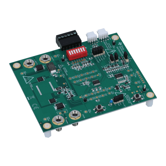
The bq76920EVM evaluation module (EVM) is a complete evaluation system for the bq76920, a 3-cell to
5-cell Li-Ion battery analog front end (AFE) integrated circuit. The EVM consists of a bq76920 circuit
module which is used for simple evaluation of the bq76920 AFE and bq78350 gauge functions. The circuit
module includes one bq76920 integrated circuit (IC), sense resistor, power FETs, and all other onboard
components necessary to protect the cells from overcharge, over discharge, short circuit, and overcurrent
discharge in a 5-series cell Li-Ion or Li-Polymer battery pack. The circuit module connects directly across
the cells in a battery. With a compatible interface board and Microsoft
user interface (GUI) software, the user can view the device registers, adjust protection limits and enable
FET control outputs.
.......................................................................................................................
1
1.1
1.2
1.3
1.4
2
2.1
2.2
3
4
4.1
4.2
4.3
Interface Adapter
4.4
5
5.1
5.2
5.3
5.4
5.5
5.6
5.7
5.8
5.9
6
6.1
6.2
6.3
6.4
6.5
6.6
6.7
7
7.1
7.2
8
SLVU924D - March 2014 - Revised November 2018
Submit Documentation Feedback
bq76920 Evaluation Module User's Guide
..........................................................................................................
...............................................................................................
................................................................................................
..........................................................................................
...................................................................................................
...........................................................................................................
.............................................................................................................
....................................................................................
..............................................................................................
....................................................................................................
.................................................................................................
...................................................................................
............................................................................................
.................................................................................................
...........................................................................................
...............................................................................................
...........................................................................................
......................................................................................
....................................................................................................
.........................................................................................................
.....................................................................................................
..............................................................................................
......................................................................................................
..............................................................................
.........................................................................................
..................................................................................................
.............................................................................................
.....................................................................................................
.............................................................................................
.......................................................................................................
....................................................................................................
Copyright © 2014-2018, Texas Instruments Incorporated
SLVU924D - March 2014 - Revised November 2018
Contents
...............................................
...........................................................
...................................................................
..........................................................................
bq76920 Evaluation Module User's Guide
User's Guide
Windows
based PC graphical
®
®
3
3
3
3
3
4
4
4
8
8
8
8
8
9
13
13
14
14
14
15
17
18
19
21
21
21
22
22
23
25
26
26
28
28
37
43
1
Advertisement
Table of Contents

Subscribe to Our Youtube Channel
Related Manuals for Texas Instruments bq76920EVM


Summary of Contents for Texas Instruments bq76920EVM
-
Page 1: Table Of Contents
SLVU924D – March 2014 – Revised November 2018 bq76920 Evaluation Module User's Guide The bq76920EVM evaluation module (EVM) is a complete evaluation system for the bq76920, a 3-cell to 5-cell Li-Ion battery analog front end (AFE) integrated circuit. The EVM consists of a bq76920 circuit module which is used for simple evaluation of the bq76920 AFE and bq78350 gauge functions. - Page 2 Microsoft, Windows are registered trademarks of Microsoft Corporation. All other trademarks are the property of their respective owners. bq76920 Evaluation Module User's Guide SLVU924D – March 2014 – Revised November 2018 Submit Documentation Feedback Copyright © 2014–2018, Texas Instruments Incorporated...
-
Page 3: Features
Electronic load or assorted resistors, calibrated load or load with accurate current meter required for gauge evaluation Additional equipment may be desired to operate the bq76920 with a more extensive demonstration. SLVU924D – March 2014 – Revised November 2018 bq76920 Evaluation Module User's Guide Submit Documentation Feedback Copyright © 2014–2018, Texas Instruments Incorporated... -
Page 4: Bq76920 Evm Quick Start Guide
The following warnings and cautions are noted for the safety of anyone using or working close to the bq76920 EVM. Observe all safety precautions. Warning The bq76920EVM circuit module may become hot during operation due to dissipation of heat. Avoid contact with the board. Follow all applicable safety procedures applicable to your laboratory. -
Page 5: Evm Connection For Basic Afe Operation
EV2300 DC Power Supply on for power supply Boot switch Figure 1. EVM Connection for Basic AFE Operation SLVU924D – March 2014 – Revised November 2018 bq76920 Evaluation Module User's Guide Submit Documentation Feedback Copyright © 2014–2018, Texas Instruments Incorporated... - Page 6 Write to Data Memory button. Read data memory if desired to confirm the new value. 15. Send a Reset command using the Commands view or the from the Advanced Comm SMB view. bq76920 Evaluation Module User's Guide SLVU924D – March 2014 – Revised November 2018 Submit Documentation Feedback Copyright © 2014–2018, Texas Instruments Incorporated...
-
Page 7: Evm Connection For Basic Gauge Operation
Power Supply Boot Switch DC Power Supply Electronic Load Figure 2. EVM Connection for Basic Gauge Operation SLVU924D – March 2014 – Revised November 2018 bq76920 Evaluation Module User's Guide Submit Documentation Feedback Copyright © 2014–2018, Texas Instruments Incorporated... -
Page 8: Interface Adapter
If you have used an EV2300 with your computer previously, no additional installation is required. EV2300 drivers are included in the bq76940 software installation package and are found in the installation directory after installing the software, typically at c:\Program Files (x86)\Texas Instruments\bq76940. Alternatively or for the bqStudio software, drivers are found at http://e2e.ti.com/support/power_management/battery_management/m/videos__files/458983.aspx... -
Page 9: Software Operation
Start the software from the desktop shortcut bq769X0 Evaluation Software or the menu Start → All Programs → Texas Instruments → bq769X0 Eval Software. When started, the software looks for the communication interface and the device. If either is not found, a popup window appears and must be acknowledged. -
Page 10: Registers View
4. It shows the control register values. If another view is displayed it is selected using the Registers button on the left side of the window or from the menu. Figure 4. Registers View bq76920 Evaluation Module User's Guide SLVU924D – March 2014 – Revised November 2018 Submit Documentation Feedback Copyright © 2014–2018, Texas Instruments Incorporated... - Page 11 The I2C Command box for each section specifies the starting register address for the transaction. SLVU924D – March 2014 – Revised November 2018 bq76920 Evaluation Module User's Guide Submit Documentation Feedback Copyright © 2014–2018, Texas Instruments Incorporated...
-
Page 12: I2C Pro View
Sequence Dialog section. Edit the sequence by selecting the file name under the sequence name in the window. Figure 6. Sequence View bq76920 Evaluation Module User's Guide SLVU924D – March 2014 – Revised November 2018 Submit Documentation Feedback Copyright © 2014–2018, Texas Instruments Incorporated... -
Page 13: Battery Management Studio Software
The Set UV Trip... file shows an example of a simpler format. Sequence files are installed to: C:\Users\<account-name>\Documents\Texas Instruments\bq76940\sequence. Sequences are loaded from this location when the program starts. Create new sequences with a text editor and save them with the .bqseq extension. -
Page 14: Installing Bqstudio
Start the software from the desktop shortcut Battery Management Studio or the menu Start → All Programs → Texas Instruments → Battery Management Studio. When started, the software looks for the communication interface and the device. If the device is found,... -
Page 15: Firmware Programming
Program button to start programming. A Progress Information window will display during programming and will close when complete. Programming typically takes about 45 s. SLVU924D – March 2014 – Revised November 2018 bq76920 Evaluation Module User's Guide Submit Documentation Feedback Copyright © 2014–2018, Texas Instruments Incorporated... -
Page 16: Firmware View
11. Note that 3 cell voltages are present. The device must be configured for operation with other cell counts, this includes basic operation of the EVM. bq76920 Evaluation Module User's Guide SLVU924D – March 2014 – Revised November 2018 Submit Documentation Feedback Copyright © 2014–2018, Texas Instruments Incorporated... -
Page 17: Data Memory Configuration
The Import tool allows loading such a file into the view so that it can be written to the device. SLVU924D – March 2014 – Revised November 2018 bq76920 Evaluation Module User's Guide Submit Documentation Feedback Copyright © 2014–2018, Texas Instruments Incorporated... -
Page 18: Chemistry View
The chemistry view is shown in Figure bq76920 Evaluation Module User's Guide SLVU924D – March 2014 – Revised November 2018 Submit Documentation Feedback Copyright © 2014–2018, Texas Instruments Incorporated... -
Page 19: Calibration
SLVU924D – March 2014 – Revised November 2018 bq76920 Evaluation Module User's Guide Submit Documentation Feedback Copyright © 2014–2018, Texas Instruments Incorporated... -
Page 20: Calibration View
Battery Management Studio Software www.ti.com Figure 14. Calibration View Figure 15. Example Voltage Calibration Successful bq76920 Evaluation Module User's Guide SLVU924D – March 2014 – Revised November 2018 Submit Documentation Feedback Copyright © 2014–2018, Texas Instruments Incorporated... -
Page 21: Device Control
The orange LED near the dip switch indicates the cell simulator has power either from the BATT+ or cell inputs. SLVU924D – March 2014 – Revised November 2018 bq76920 Evaluation Module User's Guide Submit Documentation Feedback Copyright © 2014–2018, Texas Instruments Incorporated... -
Page 22: Evaluating With Simulated Current
Table 3 shows configuration recommendations for reduced cell count. bq76920 Evaluation Module User's Guide SLVU924D – March 2014 – Revised November 2018 Submit Documentation Feedback Copyright © 2014–2018, Texas Instruments Incorporated... -
Page 23: Connecting Cells
R1 and R2. The bottom cell simulator switch can be closed to connect C0 to BATT–. SLVU924D – March 2014 – Revised November 2018 bq76920 Evaluation Module User's Guide Submit Documentation Feedback Copyright © 2014–2018, Texas Instruments Incorporated... - Page 24 4. Open the cell simulator switches, if needed Figure 19 shows an example connecting cells with an EVM configuration reduced to 4 cells. bq76920 Evaluation Module User's Guide SLVU924D – March 2014 – Revised November 2018 Submit Documentation Feedback Copyright © 2014–2018, Texas Instruments Incorporated...
-
Page 25: Connecting To A Host
AFE using the MSP430. The code is available for the TI Design and may be a helpful reference in development of a host system. SLVU924D – March 2014 – Revised November 2018 bq76920 Evaluation Module User's Guide Submit Documentation Feedback Copyright © 2014–2018, Texas Instruments Incorporated... -
Page 26: Gauge Circuits
When the charge FET turns on with a large charger voltage present, a large voltage could be impressed on the gate of the charge FET. With the voltages typically used on the bq76920EVM, this should not be high enough to damage the charge FET. If special circumstances require, the D5 pattern is available for a clamp diode. - Page 27 J11, C19, R28, R29, R33, R40, R41, R42, and R56 provide component patterns to optinally bring signals to a convenient location for evaluating the behavior of the bq78350 with a high side switch configuration. SLVU924D – March 2014 – Revised November 2018 bq76920 Evaluation Module User's Guide Submit Documentation Feedback Copyright © 2014–2018, Texas Instruments Incorporated...
-
Page 28: Bq76920Evm Circuit Module Physical Construction
The bq76920EVM consists of one circuit module assembly, PWR523. Board Layout The bq76920EVM circuit module is a 4.0-inch × 4.805-inch 4-layer circuit card assembly. It is designed for easy assembly with cell connections on the left side to a terminal block and high current terminals through banana jacks. -
Page 29: Top Silk Screen
Circuit Module Physical Construction www.ti.com Figure 21. Top Silk Screen SLVU924D – March 2014 – Revised November 2018 bq76920 Evaluation Module User's Guide Submit Documentation Feedback Copyright © 2014–2018, Texas Instruments Incorporated... -
Page 30: Top Assembly
Circuit Module Physical Construction www.ti.com Figure 22. Top Assembly bq76920 Evaluation Module User's Guide SLVU924D – March 2014 – Revised November 2018 Submit Documentation Feedback Copyright © 2014–2018, Texas Instruments Incorporated... -
Page 31: Top Layer
Circuit Module Physical Construction www.ti.com Figure 23. Top Layer SLVU924D – March 2014 – Revised November 2018 bq76920 Evaluation Module User's Guide Submit Documentation Feedback Copyright © 2014–2018, Texas Instruments Incorporated... - Page 32 Circuit Module Physical Construction www.ti.com Figure 24. Layer 2 bq76920 Evaluation Module User's Guide SLVU924D – March 2014 – Revised November 2018 Submit Documentation Feedback Copyright © 2014–2018, Texas Instruments Incorporated...
- Page 33 Circuit Module Physical Construction www.ti.com Figure 25. Layer 3 SLVU924D – March 2014 – Revised November 2018 bq76920 Evaluation Module User's Guide Submit Documentation Feedback Copyright © 2014–2018, Texas Instruments Incorporated...
-
Page 34: Bottom Layer
Circuit Module Physical Construction www.ti.com Figure 26. Bottom Layer bq76920 Evaluation Module User's Guide SLVU924D – March 2014 – Revised November 2018 Submit Documentation Feedback Copyright © 2014–2018, Texas Instruments Incorporated... -
Page 35: Bottom Silk Screen
Circuit Module Physical Construction www.ti.com Figure 27. Bottom Silk Screen SLVU924D – March 2014 – Revised November 2018 bq76920 Evaluation Module User's Guide Submit Documentation Feedback Copyright © 2014–2018, Texas Instruments Incorporated... -
Page 36: Bottom Assembly
Circuit Module Physical Construction www.ti.com Figure 28. Bottom Assembly bq76920 Evaluation Module User's Guide SLVU924D – March 2014 – Revised November 2018 Submit Documentation Feedback Copyright © 2014–2018, Texas Instruments Incorporated... -
Page 37: Bill Of Materials
Circuit Module Physical Construction www.ti.com Bill of Materials The bill of materials for the circuit module is shown in Table 4. Substitute parts may be used in the manufacturing of the assembly. Table 4. bq76920 Circuit Module Bill of Materials... - Page 38 Circuit Module Physical Construction www.ti.com Table 4. bq76920 Circuit Module Bill of Materials (continued) Designator Value Description Package Reference Part Number Alternate Alternate Part Number R16, R30 RES, 0 ohm, 5%, 0.125W, 0805 0805 CRCW08050000Z0EA Vishay-Dale 1.00k RES, 1.00k ohm, 1%, 0.125W, 0805...
- Page 39 Circuit Module Physical Construction www.ti.com Table 4. bq76920 Circuit Module Bill of Materials (continued) Designator Value Description Package Reference Part Number Alternate Alternate Part Number Black Test Point, TH, Multipurpose, Black Keystone5011 5011 Keystone TP2, TP29 Test Point, TH, Multipurpose, Red...
-
Page 40: Schematic Diagram Afe
Circuit Module Physical Construction www.ti.com Figure 29 through Figure 31 illustrate the schematics. BATT+ BOOT TP19 3.01k 4-1437565-1 BAT R 10.0k TP18 PEC02SAAN SCL pull up 1.25V TP11 TP13 TP14 PEC02SAAN SMBJ30A-13-F SDA pull up 2.2µF 10.0k 10.0k TP24... -
Page 41: Schematic Diagram Gauge
Circuit Module Physical Construction www.ti.com BCX5616TA CAP1 100k GG_PWR BSS84W-7-F TP33 -50V GG_/KEYIN 0.1µF /KEYIN 196k TP30 TP31 PEC02SAAN 100k TP36 300k 49.9k Green 25 ppm/C GG_/PRES BSS138 /PRES Addr select Green PEC02SAAN SMBA 5.6V 5.6V Green 100k 100k... -
Page 42: Schematic Diagram Cell Simulator
Circuit Module Physical Construction www.ti.com BATT+ 1.00k 76SB07ST 1.00k Orange Test points BATT– Figure 31. Schematic Diagram Cell Simulator bq76920 Evaluation Module User's Guide SLVU924D – March 2014 – Revised November 2018 Submit Documentation Feedback Copyright © 2014–2018, Texas Instruments Incorporated... -
Page 43: Related Documents From Texas Instruments
Added Sequence_Example.bqseq to paragraph below Sequence View image........• Changed content in the BOM in rows containing U1 and U2 in the Designator column. SLVU924D – March 2014 – Revised November 2018 Revision History Submit Documentation Feedback Copyright © 2014–2018, Texas Instruments Incorporated... - Page 44 Changed last sentence in the Cell Simulator section......................• Changed adapter in figure..............• Added reference and figure to Reducing the Cell Count section. Revision History SLVU924D – March 2014 – Revised November 2018 Submit Documentation Feedback Copyright © 2014–2018, Texas Instruments Incorporated...
- Page 45 Added spark gaps, changed fiducials to uninstalled, and bq78350 version in the BOM table..........• Changed gauge documents to -R1 and added references in related documents. SLVU924D – March 2014 – Revised November 2018 Revision History Submit Documentation Feedback Copyright © 2014–2018, Texas Instruments Incorporated...
- Page 46 TI products. TI’s provision of these resources does not expand or otherwise alter TI’s applicable warranties or warranty disclaimers for TI products. Mailing Address: Texas Instruments, Post Office Box 655303, Dallas, Texas 75265 Copyright © 2018, Texas Instruments Incorporated...
Need help?
Do you have a question about the bq76920EVM and is the answer not in the manual?
Questions and answers