Table of Contents
Advertisement
Quick Links
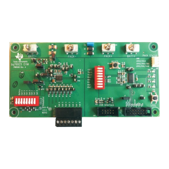
This user's guide for the bq76925EVM evaluation module can assist designers in their evaluation of the
bq76925, Analog Front End for 3- to 6-Series Lithium-Ion Cells. This guide discusses setup and operation
of the module and contains schematics, bill of materials, and printed-circuit board layout.
Before designing a battery management system with the bq76925, designers are advised to read the
bq76925 data sheet (SLUSAM9).
.....................................................................................................................
1
1.1
1.2
1.3
2
2.1
2.2
2.3
2.4
2.5
2.6
3
3.1
3.2
3.3
3.4
3.5
4
4.1
4.2
4.3
4.4
5
5.1
5.2
5.3
5.4
5.5
5.6
5.7
5.8
5.9
5.10
5.11
5.12
Adobe, Reader are trademarks of Adobe Systems Incorporated.
Pentium is a trademark of Intel Corporation.
Mentor Graphics, PADs are trademarks of Mentor Graphics Corporation.
Microsoft, Windows, Excel are trademarks of Microsoft Corporation.
I2C is a trademark of Philips Electronics N.V..
SLUU514 - July 2011
Submit Documentation Feedback
bq76925EVM Evaluation Module
.............................................................................................................
.........................................................................................................
.........................................................................................
..........................................................................................
........................................................................................................
............................................................................................
........................................................................................................
...........................................................................................................
....................................................................................................
...............................................................................................
......................................................................................
...............................................................................
...................................................................................
.........................................................................................
..........................................................................................
..................................................................................
.....................................................................................
......................................................................................
............................................................................................
....................................................................................
................................................................................................
...........................................................................................
................................................................................................
..................................................................................................
.......................................................................................................
.................................................................................
...............................................................................................
............................................................................................
.....................................................................................................
.......................................................................................................
............................................................................................................
Copyright © 2011, Texas Instruments Incorporated
Contents
......................................................
............................................................
..........................................................................
User's Guide
SLUU514 - July 2011
bq76925EVM Evaluation Module
4
4
4
4
6
6
8
10
10
11
11
11
11
12
12
12
13
16
16
18
19
19
21
21
22
22
23
23
23
24
24
24
25
25
26
1
Advertisement
Table of Contents

Related Manuals for Texas Instruments bq76925EVM


Summary of Contents for Texas Instruments bq76925EVM
-
Page 1: Table Of Contents
SLUU514 – July 2011 bq76925EVM Evaluation Module This user's guide for the bq76925EVM evaluation module can assist designers in their evaluation of the bq76925, Analog Front End for 3- to 6-Series Lithium-Ion Cells. This guide discusses setup and operation of the module and contains schematics, bill of materials, and printed-circuit board layout. - Page 2 Schematic – Page 1 of 4 ....................Schematic – Page 2 of 4 ....................Schematic – Page 3 of 4 ....................Schematic – Page 4 of 4 SLUU514 – July 2011 bq76925EVM Evaluation Module Submit Documentation Feedback Copyright © 2011, Texas Instruments Incorporated...
- Page 3 Example Log File ................Example of a Device Connect Command ....................Data From MSP430F2122 ................Example of a Device Connect Command ......................Bill of Materials SLUU514 – July 2011 bq76925EVM Evaluation Module Submit Documentation Feedback Copyright © 2011, Texas Instruments Incorporated...
-
Page 4: Overview
The bq76925 Evaluation Software is the Microsoft™ Windows™ application that controls and interfaces with the bq76925. Installation of this software on a compatible personal computer (PC) is required. The installation file can be found on the product page for the bq76925 on the Texas Instruments Web site. 1.3.2... - Page 5 A color monitor with 1024 × 768 or better resolution 1.3.3 USB-TO-GPIO Adapter The USB-TO-GPIO Adapter is actually an EVM available from Texas Instruments. It is used to provide the I2C connection between the bq76925 and the PC. CAUTION The USB-TO-GPIO Adapter original firmware is 1.0.10. Firmware version 2.0.19 or later must be installed using the USB-TO-GPIO Firmware Updater...
-
Page 6: Circuit Details And Configuration
The BATT± connections are single, heavy-duty screw terminals that feature a 6-32 × 1/4-in.-long screw. This connector is rated to 30 A, maximum. Actual current is limited to a lower value (20 A) by other circuit board components. SLUU514 – July 2011 bq76925EVM Evaluation Module Submit Documentation Feedback Copyright © 2011, Texas Instruments Incorporated... -
Page 7: Cell Voltage Connections
MSP-FET430UIF. Use of this connector is not required for evaluation of the bq76925. This header is for those users who wish to write code for the MSP430F2122 resident on the EVM. The pin assignment is as follows: SLUU514 – July 2011 bq76925EVM Evaluation Module Submit Documentation Feedback Copyright © 2011, Texas Instruments Incorporated... -
Page 8: Configuration Jumpers And Switches (J1 - J6, S2, S4)
Header Name Position Purpose 1 - 2 Internal V3P3 selected. Not recommended when SOC LEDs are being used. 2 - 3 External V3P3 selected. (default) SLUU514 – July 2011 bq76925EVM Evaluation Module Submit Documentation Feedback Copyright © 2011, Texas Instruments Incorporated... -
Page 9: J3, V3P3 Pin Circuit Configuration
Cell 2 Applies simulated cell voltage to VC2. Cell 1 Applies simulated cell voltage to VC1. Cell 0 Applies simulated cell voltage to VC0. SLUU514 – July 2011 bq76925EVM Evaluation Module Submit Documentation Feedback Copyright © 2011, Texas Instruments Incorporated... -
Page 10: Pushbuttons (S1, S3)
The first 20 test points correspond one-to-one to the pin number on the bq76925. Table 13. Test Points Label Ground Reference Test Point VCTL TP10 TP11 SENSEN TP12 SENSEP SLUU514 – July 2011 bq76925EVM Evaluation Module Submit Documentation Feedback Copyright © 2011, Texas Instruments Incorporated... -
Page 11: Bq76925
The bq76925 Evaluation Software and the USB-TO-GPIO Adapter must be installed and set up. The USB-TO-GPIO Adapter is an EVM that is sold separately from the bq76925EVM. The firmware in it must be changed to work with the bq76925 because this EVM was developed for generic applications. Go to the TI Web site to download the firmware loader. -
Page 12: Configuration Switches And Jumpers
Table 14 has been verified. The bq76925EVM must be powered from a power supply for this demonstration. The power supply drives an onboard cell simulator as well as powers the bq76925 and MSP430 circuitry. No battery is required at this point. -
Page 13: Bq76925 Evaluation Software
With polling active, the cell voltages and temperatures update on a periodic basis. The poll indicator light next to the word POLL flashes between green and orange for each poll cycle. SLUU514 – July 2011 bq76925EVM Evaluation Module Submit Documentation Feedback Copyright © 2011, Texas Instruments Incorporated... -
Page 14: Poll Button In The Evaluation Software
One way to easily simulate battery current is to apply a millivolt source to the current-sense inputs of the bq76925. Tens of amperes can be simulated where each 10 mV is equal to 10 amperes. SLUU514 – July 2011 bq76925EVM Evaluation Module Submit Documentation Feedback Copyright © 2011, Texas Instruments Incorporated... -
Page 15: Demo With Two Power Supplies
J5 and the BATT- terminal. This simulates approximately –50 A or –50,000 mA, of discharge current. Figure 5. Voltage, Temperature, and Current Measurement in the Evaluation Software SLUU514 – July 2011 bq76925EVM Evaluation Module Submit Documentation Feedback Copyright © 2011, Texas Instruments Incorporated... -
Page 16: Control Register Demonstration
Open the Evaluation Software, if not already open, and click the checkbox marked Show Volatile Control Registers. Figure 7. Volatile Control Registers Checkbox This expands the home window to show the six registers. SLUU514 – July 2011 bq76925EVM Evaluation Module Submit Documentation Feedback Copyright © 2011, Texas Instruments Incorporated... -
Page 17: Volatile Control Registers Access
If the SLEEP bit is a 1, it halts communications, so that the status of this bit is unable to be displayed. The SLEEP bit always appears to be OFF or MASKED. SLUU514 – July 2011 bq76925EVM Evaluation Module Submit Documentation Feedback Copyright © 2011, Texas Instruments Incorporated... -
Page 18: Control Registers Introduction
. For those details, see SLUSAM9. Mousing over a bit in the Control Register section of the software displays a brief description of the bit. SLUU514 – July 2011 bq76925EVM Evaluation Module Submit Documentation Feedback Copyright © 2011, Texas Instruments Incorporated... -
Page 19: Modifying Control Registers
SLEEP. When this bit is set to a 1, the part shuts down the V3P3 output and enters the low-power state. To enter sleep mode, simply click the SLEEP bit in the Control Registers display. SLUU514 – July 2011 bq76925EVM Evaluation Module Submit Documentation Feedback Copyright © 2011, Texas Instruments Incorporated... -
Page 20: Sleep Mode Showing 3.3-V Status
Figure 10. Sleep Mode Showing 3.3-V Status The method to wake the part from sleep is to apply a voltage, 3.3 V in the case of the bq76925EVM, to the ALERT pin. This is accomplished easily by clicking the Wake button in the Hardware IO Section. -
Page 21: Control Panel Demonstration
Advanced. Figure 12. Open Control Panel Figure 13. Control Panel Details SLUU514 – July 2011 bq76925EVM Evaluation Module Submit Documentation Feedback Copyright © 2011, Texas Instruments Incorporated... -
Page 22: Measurement Tab
8. Delay 40 µs, get A/D Counts for VC4. 9. Set VCOUT to Read VC3. 10. Delay 40 µs, get A/D Counts for VC3. 11. Set VCOUT to Read VC2. SLUU514 – July 2011 bq76925EVM Evaluation Module Submit Documentation Feedback Copyright © 2011, Texas Instruments Incorporated... -
Page 23: Vcout Readings
´ 0.001 + VREF VREF NOMINAL And, G must be set to 0.6 for the bq76925EVM. VCOUT The VCn in Table 16 is the millivolt reading shown in the measurement window. VIOUT Readings The VIOUT readings are shown in millivolts and labeled as SENSEP and SENSEN. The SENSEN readings are done with I_AMP_CAL set to zero and are only taken in the first 5 seconds of polling while the VIOUT signal level stabilizes. -
Page 24: Eeprom Correction Registers
(B) Two radio buttons allow the user to select the current polarity for the Current Comparator Threshold. This is bit 3 of the CONFIG_1 register. SLUU514 – July 2011 bq76925EVM Evaluation Module Submit Documentation Feedback Copyright © 2011, Texas Instruments Incorporated... -
Page 25: Power Control
The logging tab is another convenience feature. It allows the user to record the I2C transactions that take place between the bq76925 software and the bq76925. SLUU514 – July 2011 bq76925EVM Evaluation Module Submit Documentation Feedback Copyright © 2011, Texas Instruments Incorporated... -
Page 26: Log File
Temperature Temperature 6/15/2011 9:52 3953 3935 3878 3943 3949 3944 27.4 26.8 –722 6/15/2011 9:52 3953 3940 3878 3938 3949 3940 27.4 26.7 –722 SLUU514 – July 2011 bq76925EVM Evaluation Module Submit Documentation Feedback Copyright © 2011, Texas Instruments Incorporated... -
Page 27: Communications Tab
The default condition of the monitor is to be off. Click on the checkbox below the window that is labeled Enable to enable the monitor. The Clear button erases the contents of the monitor window, if clicked. SLUU514 – July 2011 bq76925EVM Evaluation Module Submit Documentation Feedback Copyright © 2011, Texas Instruments Incorporated... -
Page 28: Transactions During A Connect To Device Command
I2C_R: I2C_W: I2C_R: I2C_R: I2C_W: I2C_R: I2C_R: I2C_W: I2C_R: I2C_R: I2C_R: I2C_R: I2C_R: I2C_R: I2C_R: I2C_R: I2C_R: I2C_R: I2C_R: I2C_R: I2C_R: I2C_R: I2C_R: I2C_R: SLUU514 – July 2011 bq76925EVM Evaluation Module Submit Documentation Feedback Copyright © 2011, Texas Instruments Incorporated... -
Page 29: I2C
Byte Name Description Units Number Status of Alert pin. Bit zero indicates level Status of Alert pin: None 1=High, 0=Low (Overcurrent). Reserved Reserved None SLUU514 – July 2011 bq76925EVM Evaluation Module Submit Documentation Feedback Copyright © 2011, Texas Instruments Incorporated... -
Page 30: Example Of I2C Communications From Msp430F2122
I2C_W: I2C_R: I2C_W: I2C_R: I2C_W: I2C_R: I2C_W: I2C_R: I2C_W: I2C_R: I2C_W: I2C_R: I2C_W: I2C_R: I2C_W: I2C_R: I2C_W: I2C_R: I2C_W: I2C_R: I2C_W: I2C_R: I2C_W: I2C_R: bq76925EVM Evaluation Module SLUU514 – July 2011 Submit Documentation Feedback Copyright © 2011, Texas Instruments Incorporated... -
Page 31: 3-, 4-, And 5-Cell Operation
(VCOUT, VIOUT and VTB) and then reading the results from the MSP430. 3-, 4-, and 5-Cell Operation This section includes instructions for setting up the bq76925EVM for operation with less than 6 cells. The discussion considers operation with the cell simulator only. -
Page 32: Four-Cell Operation
8. Connect to the evaluation software. 9. Change the Select Cell Count drop-down box on the home screen to 3. Operation With Cells This section discusses operating the bq76925EVM with a real cell pack. Preparing Circuit for Operation CAUTION Improper operation with real lithium-ion cells can cause permanent damage to the bq76925EVM. -
Page 33: Battery Connection Sequence
USB-TO-GPIO Adapter or MSP-FET430UIF that may be connected. Battery Connection Sequence The connection of a real battery pack to the bq76925EVM requires a certain connection sequence for safe operation. The fundamental connection sequence is: 1. Ensure that all switches on S4 are open. -
Page 34: Three-Cell Operation
10. Change the Select Cell Count drop-down box on the home screen to 4. Battery Removal Sequence The removal of the battery from the bq76925EVM requires a certain sequence for safe operation. The connection removal sequence is: 1. Remove USB-TO-GPIO connector at CN8. -
Page 35: Schematics
Schematic and Bill of Materials www.ti.com Schematics Figure 19. Schematic – Page 1 of 4 SLUU514 – July 2011 bq76925EVM Evaluation Module Submit Documentation Feedback Copyright © 2011, Texas Instruments Incorporated... -
Page 36: Schematic
Schematic and Bill of Materials www.ti.com Figure 20. Schematic – Page 2 of 4 Figure 21. Schematic – Page 3 of 4 SLUU514 – July 2011 bq76925EVM Evaluation Module Submit Documentation Feedback Copyright © 2011, Texas Instruments Incorporated... -
Page 37: Bill Of Materials
MOSFETs, Pch, –50V, –0.13A, 10 Ω SOT23 BSS84 Fairchild MOSFETS, Nch, 50V, 0.22A, 3.5 Ω SOT23 BSS138 Fairchild 200K Resistor, Chip, 1/10W, 5% 0805 Standard Standard SLUU514 – July 2011 bq76925EVM Evaluation Module Submit Documentation Feedback Copyright © 2011, Texas Instruments Incorporated... -
Page 38: Printed-Circuit Board
PCB, 6 In x 3 In x 0.062 In PWR008 Printed-Circuit Board This section includes the plots of the printed-circuit board layers. Figure 23. Top Silkscreen Layer SLUU514 – July 2011 bq76925EVM Evaluation Module Submit Documentation Feedback Copyright © 2011, Texas Instruments Incorporated... -
Page 39: Top Copper Layer
Printed-Circuit Board www.ti.com Figure 24. Top Copper Layer Figure 25. Inner Copper Layer SLUU514 – July 2011 bq76925EVM Evaluation Module Submit Documentation Feedback Copyright © 2011, Texas Instruments Incorporated... -
Page 40: Inner Copper Layer
Printed-Circuit Board www.ti.com Figure 26. Inner Copper Layer Figure 27. Bottom Copper Layer SLUU514 – July 2011 bq76925EVM Evaluation Module Submit Documentation Feedback Copyright © 2011, Texas Instruments Incorporated... -
Page 41: Drill Drawing
Printed-Circuit Board www.ti.com Figure 28. Drill Drawing SLUU514 – July 2011 bq76925EVM Evaluation Module Submit Documentation Feedback Copyright © 2011, Texas Instruments Incorporated... - Page 42 Evaluation Board/Kit Important Notice Texas Instruments (TI) provides the enclosed product(s) under the following conditions: This evaluation board/kit is intended for use for ENGINEERING DEVELOPMENT, DEMONSTRATION, OR EVALUATION PURPOSES ONLY and is not considered by TI to be a finished end-product fit for general consumer use. Persons handling the product(s) must have electronics training and observe good engineering practice standards.
- Page 43 IMPORTANT NOTICE Texas Instruments Incorporated and its subsidiaries (TI) reserve the right to make corrections, modifications, enhancements, improvements, and other changes to its products and services at any time and to discontinue any product or service without notice. Customers should obtain the latest relevant information before placing orders and should verify that such information is current and complete.
- Page 44 Mouser Electronics Authorized Distributor Click to View Pricing, Inventory, Delivery & Lifecycle Information: Texas Instruments BQ76925EVM...
Need help?
Do you have a question about the bq76925EVM and is the answer not in the manual?
Questions and answers