Nivus NivuFlow Mobile 600 Instruction Manual
Flow measurement transmitter
Hide thumbs
Also See for NivuFlow Mobile 600:
- Instruction manual (149 pages) ,
- Instruction manual (140 pages) ,
- Instruction manual (194 pages)
Table of Contents
Advertisement
Quick Links
F L O W p o r t a b l e
Instruction Manual
Flow Measurement Transmitter
NivuFlow Mobile 600
Firmware Revision: 1.5
Document revision: 00 / 04.09.2017
Original Manual: German / rev. 00 as of 31.07.2017
I n s t r u m e n t a t i o n
f o r
W a t e r
I n d u s t r y
NIVUS GmbH • Im Taele 2 • D-75031 Eppingen • Internet: www.nivus.com
Phone: +49 (0) 7262 9191-0 • Fax: +49 (0) 7262 9191-999 • E-Mail: info@nivus.com
Advertisement
Table of Contents

Subscribe to Our Youtube Channel
Related Manuals for Nivus NivuFlow Mobile 600


Summary of Contents for Nivus NivuFlow Mobile 600
- Page 1 W a t e r I n d u s t r y NIVUS GmbH • Im Taele 2 • D-75031 Eppingen • Internet: www.nivus.com Phone: +49 (0) 7262 9191-0 • Fax: +49 (0) 7262 9191-999 • E-Mail: info@nivus.com...
- Page 2 INCHEON, Korea 406-840 www.nivus.de Phone: +82 32 209 8588 Fax: +82 32 209 8590 korea@nivus.com NIVUS Sp. z o.o., Poland www.nivus.com ul. Hutnicza 3 / B-18 81-212 Gdynia, Poland Phone: +48 (0) 58 7602015 NIVUS Vietnam 21 Pho Duc Chinh, Ba Dinh,...
-
Page 3: Copyrights And Property Rights
Copyrights and property rights Copyrights and property rights This document and its contents are proprietary to NIVUS GmbH and are not to be reproduced or copied without the express written permission of NIVUS GmbH. Violations oblige to compensation. Important Note This instruction manual may exclusively - even in parts - be copied or translated in any other way with the express written consent of NIVUS GmbH. -
Page 4: Table Of Contents
Instruction manual NivuFlow Mobile 600 Table of contents COPYRIGHTS AND PROPERTY RIGHTS GENERAL About this manual ...............11 Applicable documentation ............. 11 1.2 Signs and definitions used ............11 Connections and Operating Elements ........12 Power Supply ................12 2.1.1 Transmitter................12 2.1.2 Rechargeable Batteries ............12 NivuFlow Operating Elements ............ - Page 5 Table of contents PRODUCT SPECIFICATION Product Construction and Overview .........18 Enclosure Dimensions ..............19 Connectable Sensors ..............19 9.3 Device identification ..............19 10 Specifications ................20 11 Configuration ................21 11.1 Device Types and Accessories ............. 21 11.2 Delivery ..................21 11.3 Reception inspection ..............21 11.4 Storage ..................22 11.5 Transport..................22 11.6 Return ...................22...
- Page 6 Instruction manual NivuFlow Mobile 600 15 Electrical Installation/Power Supply ..........29 15.1 Rechargeable Battery Pack ............30 15.1.1 Removing/Inserting the Rechargeable Battery Pack ..30 15.1.2 Charging the rechargeable battery pack ......30 15.1.3 Operation/Charging with direct connection to mains power 32 15.1.4...
- Page 7 Table of contents START-UP EXAMPLES 23 Measurement with Clamp-On Sensors ........56 23.1 General ..................56 23.2 Programming a 1-path diametrically opposed Measurement ..56 23.2.1 Simple Parameter Setting ........... 56 23.2.2 Extended Parameter Setting ..........59 24 Measurement with wet Sensors ..........60 PARAMETER SETTING 25 General Programming ..............61 25.1 Save Parameters ................61...
- Page 8 Instruction manual NivuFlow Mobile 600 28 Application Parameters Menu ............72 28.1 Menu Measure Place ..............72 28.1.1 Name of Measurement Place ..........73 28.1.2 Transit Time Mode .............. 73 28.1.3 Number of Paths ..............74 28.1.4 Medium ................74 28.1.5 Medium Temperature ............74 28.1.6 Channel Profiles ..............
- Page 9 Table of contents 30 System Parameter Menu .............94 30.1 Information ..................94 30.2 Region Settings ................95 30.2.1 (Operation) Language ............95 30.2.2 Date Format ................ 95 30.2.3 Units ...................95 30.2.4 Units Memory ..............96 30.3 Time/Date ..................97 30.4 Error Messages ................98 30.5 Service ..................99 30.5.1 Service Level ..............
- Page 10 Instruction manual NivuFlow Mobile 600 DIAGNOSTICS 35 Diagnostic Menu Principles ............108 36 Menu Diagnostics v-Paths ............109 37 Diagnostic Inputs/Outputs ............110 37.1 Important Information on the Simulation ........110 38 Diagnostic Menu Signal Analysis ..........113 39 Simulation ..................118 MAINTENANCE AND CLEANING 40 Maintenance ................119...
-
Page 11: General
Technical Instruction for Transit Time Sensors • Installation Instruction for Transit Time Sensors These manuals are provided with the auxiliary units or sensors and/or are available as down- load on the NIVUS homepage. Signs and definitions used Image Meaning Remark (Action) Step Action to be performed by you. -
Page 12: Connections And Operating Elements
Instruction manual NivuFlow Mobile 600 Connections and Operating Elements Power Supply 2.1.1 Transmitter The NivuFlow Mobile (Fig. 2-1 pos. 1) is supplied by rechargeable battery packs. Once plugged in the batteries are connected to the transmitter via the charging pins (Fig. 2-1 pos. 4) supplying the required operating voltage. -
Page 13: Nivuflow Operating Elements
General NivuFlow Operating Elements NivuFlow itself has no direct operating elements. Instrument operation and the setting of parameters are carried out completely by using smartphone, tablet, notebook and PC. Use here the PC mouse or the touchscreen. Also refer to the instruction manuals of your preferred smartphone, tablet, notebook or PC. -
Page 14: Safety Instructions
Instruction manual NivuFlow Mobile 600 Safety Instructions In general: Used symbols and signal words Valuation of the accident level The general warning symbol indicates the risk of personal injuries or death. In the text section the general warning symbol is used in conjunction with the signal words described below. -
Page 15: Warning Notices On The Product (Option)
Safeguards and Precautions Working with NIVUS instruments requires to observe and to follow the safety measures and precautions below generally and at any time. These notes and warnings will not be repeated for each description within the document. -
Page 16: Liability Disclaimer
All operations on the device which go beyond installation or connection measures in principle shall be carried out by NIVUS staff or personnel authorised by NIVUS due to reasons of safety and guarantee. -
Page 17: User's Responsibilities
Safety Instructions User’s Responsibilities Important Note In the EEA (European Economic Area) national implementation of the frame-work directive 89/391/EEC and corresponding individual directives, in particular the directive 2009/104/EC concerning the minimum safety and health requirements for the use of work equipment by workers at work, as amended, are to be observed and adhered to. -
Page 18: Product Specification
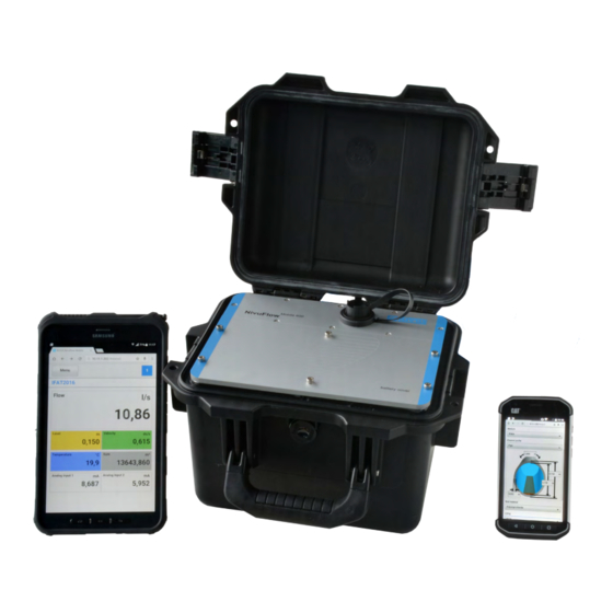
Right battery pack receptacle (position to charge the battery) Cover (not shown) above batteries with six non-detachable hexagon socket screws USB-A interface NivuFlow Mobile 600 transmitter (IP67) Enclosure (IP68 with cover closed) Fig. 9-1 Device construction NivuFlow Mobile 600 with enclosure page 18 rev. 00 / 04.09.2017... -
Page 19: Enclosure Dimensions
Product Specification Enclosure Dimensions Fig. 9-2 Dimensions Connectable Sensors The photo below provides an overview on the connectable sensors. Clamp-on sensor pair type NIC-CO01 Pipe sensor NIS -V200RL0 Fig. 9-3 Connectable sensors Device identification The instructions contained within this manual are valid only for the type of device specified on the title page. -
Page 20: Specifications
Check the nameplate for correct specification of the power supply. The declaration of conformity is located at the end of the manual. Nameplates Fig. 9-4 Nameplate NivuFlow Mobile 600 10 Specifications Measurement principle Ultrasonic transit time (time of flight) - 2x rechargeable batteries 12 V / 15 Ah, lead gel Power supply - Battery charger 100...240 V AC / 50...60 Hz / 50 VA... -
Page 21: Configuration
„43 Accessories“ starting on page 121, the current price list or contact NIVUS. 11.2 Delivery The standard delivery of the NivuFlow Mobile 600 basically contains: • Transmitter type NivuFlow Mobile 600 (according to shipping documents) • Ring magnet (solenoid) •... -
Page 22: Storage
Take precautionary measures and use lashing straps or similar to protect the NivuFlow from heavy shocks or vibrations. 11.6 Return In case of a required reshipment return the unit at customer cost to NIVUS GmbH in Eppingen using the original packaging. Insufficiently franked shipments will not be accepted! Ü... -
Page 23: Installation Of Spare Parts And Parts Subject To Wear And Tear
Installation and/or the use of such products hence may negatively influence predetermined constructional characteristics of the measurement system or even lead to instrument failures. NIVUS cannot be held responsible for any damage resulting due to the use of non-original parts and non-original accessories. -
Page 24: Functional Description
It is used in full pipes and rectangular geometries with different dimensions. NivuFlow Mobile 600 with clamp-on sensors is a contactless measurement system and hence is independent from pressure. Clamp-on measurement systems are suitable only for full pipes. -
Page 25: Functional Principle
Functional description 13 Functional Principle 13.1 Flow Velocity Detection The flow velocity is determined by using the ultrasonic transit time principle. Sensor 1 Sensor 2 α defined angle Time of impulse towards flow direction Time of impulse in flow direction Transit time Fig. - Page 26 Instruction manual NivuFlow Mobile 600 The transit time difference can be approximated if: • the main flow direction is known and • C >> ʋ is assumed Here the formula below is used: υ ⋅ ∆ − − assumed: • = length of acoustic measurement path between sensors 1 and 2 •...
-
Page 27: Flow Calculation
Functional description 13.2 Flow Calculation In case of using single-path or multi-path installations in one level under the condition Q = ʋ • A average • given ʋ = average flow velocity ƒ average A = cross-sectional flow area ƒ It is required to involve a velocity coefficient “k” to compensate the difference between the measured velocity ʋ and the average velocity ʋ... -
Page 28: Installation And Connection
PU stickers on enclosure frame Ü Â Prior to first use of the NivuFlow Mobile 600 make sure that the PU stickers have been removed. If not, remove the stickers and clean the enclosure frame if necessary. See chapter „11.3 Reception inspection“. -
Page 29: Securing The Instrument
The protection degree of the (closed) instrument is IP68 even with open connection sockets. Damaged or lost caps can be purchased from NIVUS. 15 Electrical Installation/Power Supply... -
Page 30: Rechargeable Battery Pack
Fully charge the inserted battery prior to the initial instrument start. Power adapter/battery charger To charge the rechargeable battery pack use the NIVUS power adapter/battery charger (Fig. 15-1; art.-no. NFM0 ZLAD) only. Observe the specifications attached on the power adapter/battery charger. - Page 31 Installation and Connection Power adapter/battery charger with connection cable for the multifunction socket on NFM or the charging tray LED indicating the charging status Fig. 15-1 Power adapter/battery charger Disconnect the power adapter/battery charger from mains power (Fig. 15-1) before you con- nect/disconnect it to/from a rechargeable battery.
-
Page 32: Operation/Charging With Direct Connection To Mains Power
By using the multifunction socket the NivuFlow Mobile can be also operated with alternative power sources such as solar panels. NIVUS provides a particular 2-wire connection cable (art.-no. NFM0 ZVER PS) with open cable ends on one side and a plug for the multifunction socket on the other side. -
Page 33: Installation Of Sensors
Installation and Connection The NivuFlow Mobile power input accepts 12...32 V and is protected against overvoltage, overcurrent and reverse polarity. Charge/Discharge battery sockets While charging only the battery plugged into the right socket is charged however. When discharging the battery with the higher capacity (independent of the socket) is used until the capacity of both batteries has reached the same level. - Page 34 Instruction manual NivuFlow Mobile 600 • Material of pipe lining • Medium to measure (type of liquid) Based on these specifications the transmitter calculates the accurate position data for the sensor installation. The mounting data can be viewed on the display and operation module (smartphone, tablet, notebook etc.).
-
Page 35: Installation Of Wet Sensors
Installation and Connection sender/receiver sender/receiver Fig. 16-4 Example “Diametrical W” mode 16.3 Installation of wet Sensors Important Note Wet sensors shall be installed only by a pipeline company or a plumber. The tightness of pipes must be guaranteed at any time. The measurement is not influenced by pipe material or pipe wall thickness if wet sensors are used. -
Page 36: Sensor Connection
When positioning sensors or nozzles make sure to observe a parallel distance of 1x diameter (guideline) between the sensor centres per pipe crossing. If NIVUS pipe sensors are used the installation angle shall be 45°. -
Page 37: Single External Connection For Inputs/Outputs
(four sensors) used for flow velocity measurement on the NivuFlow Mobile 600 (Fig. 19-1 pos. 1). For only one single external connection refer to chapter „18 Single external Connection for Inputs/Outputs“. - Page 38 Instruction manual NivuFlow Mobile 600 Fig. 19-1 NFM with Connector Box (example) Ü Â How to fasten the Connector Box on the NivuFlow Mobile: 1. Remove the rubber buffers (not depicted) from the reverse side of the NivuFlow Mobile (Fig. 19-1 pos. 1). Both fastening plates (now loose, Fig. 19-1 pos. 3) within the screw channels (Fig.
- Page 39 Installation and Connection 1 2 3 4 5 6 7 8 9 10 11 12 13 14 15 16 17 18 +8,7 V DC RxTx- RxTx+ Shield AE1 - AE1 + AE2 - AE2 + AE3 + GND AE3/AA DE 3,3 V 12 - 14 V (+) Root contact (COM) Normally closed (NO)
-
Page 40: Putting Into Operation
Instruction manual NivuFlow Mobile 600 Putting into Operation 20 Notes to Users Before connecting and operating the NivuFlow Mobile follow the instructions below. This instruction manual contains any information required for the setting of parameters and the operation of the instrument. The manual is intended for technically qualified personnel. -
Page 41: Android Os
Putting into Operation 21.2 Android OS Ü Â Preparing the NivuFlow Mobile: 1. Ensure power supply: a minimum of one completely charged rechargeable battery pack either plugged into the instrument or alternatively connected via the multifunc- tion socket (see chapter „15.1.4 Alternative Power Supply“). The following step “Wake-Up” can be skipped as soon as the battery pack is inserted now or when voltage is fed and the connection is set up within the follow- ing five minutes. - Page 42 Instruction manual NivuFlow Mobile 600 Fig. 21-3 WLAN symbol 4. From the list of available WLANs select the NFM (Fig. 21-4 pos. 1) with the accord- ing SSID (default state = serial no.). Fig. 21-4 WLAN List 5. Enter the password for server access (default state = PUK) (Fig. 21-5 pos. 1) and connect (Fig.
- Page 43 Putting into Operation 6. Start the Internet browser. 7. Type “192.168.1.1” into the IP address field and open. The NivuFlow Mobile display (Fig. 21-6) is indicated as soon as the connection has been established success- fully. Fig. 21-6 NFM display in browser 8. To set a link on your “Home screen” (for direct access) use the “Tabs and Settings” symbol (Fig. 21-6 pos. 1) and select “Add to Home screen” (Fig. 21-7 pos. 1). Fig. 21-7 Add to Home screen 9. Use “Add” to confirm (Fig. 21-8 pos. 1). rev.
- Page 44 Instruction manual NivuFlow Mobile 600 Fig. 21-8 Confirm adding The link (Fig. 21-9 pos. 1) is indicated on the tart screen and can be used for instant access without the need to specify the IP address. This link can be used for each further NivuFlow Mobile transmitter after it has been selected from the WLAN list.
-
Page 45: Ios Operating System
Putting into Operation Fig. 21-10 Session Timeout 21.3 iOS Operating System Ü Â Preparing the NivuFlow Mobile: 1. Ensure power supply: a minimum of one completely charged rechargeable battery pack either plugged into the instrument or alternatively connected via the multi- function socket (see chapter „15.1.4 Alternative Power Supply“). - Page 46 Instruction manual NivuFlow Mobile 600 Fig. 21-12 Settings symbol 3. Select WLAN (Fig. 21-13 pos. 1). Fig. 21-13 WLAN symbol 4. From the list of available WLANs select the NFM (Fig. 21-14 pos. 1) with the according SSID (default state = serial no.).
- Page 47 Putting into Operation Fig. 21-15 Enter password and join 6. Start the Internet browser. 7. Type “192.168.1.1” into the IP address field and open. The NivuFlow Mobile display (Fig. 21-16) is indicated as soon as the connection has been established success- fully. Fig. 21-16 NFM display in browser 8. Use the symbol “Provide” (Fig. 21-17 pos. 1) to set up a link on your home screen (for direct access). Fig.
- Page 48 Instruction manual NivuFlow Mobile 600 Fig. 21-18 To Home Screen 10. Confirm with “Return” (Fig. 21-19 pos. 1). Fig. 21-19 Confirm adding The link (Fig. 21-20 pos. 1) is indicated on the tart screen and can be used for instant access without the need to specify the IP address.
- Page 49 Putting into Operation Fig. 21-20 Link in the start screen After five minutes of inactivity on the display and operation module the message “Session Timeout” (Fig. 21-21) is shown. Access can be restored instantly by selecting the symbol within one minute. Longer periods of inactivity require a restart of the connection process. Fig. 21-21 Session Timeout rev.
-
Page 50: Windows Os
Instruction manual NivuFlow Mobile 600 21.4 Windows OS Ü Â Preparing the NivuFlow Mobile: 1. Ensure power supply: a minimum of one completely charged rechargeable battery pack either plugged into the instrument or alternatively connected via the multi- function socket (see chapter „15.1.4 Alternative Power Supply“). - Page 51 Putting into Operation Fig. 21-23 List of (WLAN) networks (example) 4. Enter the security key (password) (default state = PUK; example here fd671a105c5d) (Fig. 21-24 pos. 1) and connect. Fig. 21-24 Enter security key and connect (example) 5. Start the Internet browser. Fig.
- Page 52 Instruction manual NivuFlow Mobile 600 Fig. 21-26 NFM display in browser 7. To create a browser favourite (for direct access) click the “Favourites” star (Fig. 21-27 pos. 1, example here Google Chrome) and confirm with “Finished” (Fig. 21-27 pos. 2). Fig. 21-27 Set up favourites (example) The bookmark is shown in the bookmarks list (Fig. 21-28 pos. 1) and can be used for instant access without the need to specify the IP address.
-
Page 53: Menu Operation/Overview
22 Menu Operation/Overview 22.1 Display Overview The NIVUS display at any time provides an overview on where you currently are within the menu structure and which entries you are about to modify. Menu / Back (depending on display view) Display area 1 (output field 1) Display area 2 (output field 2...5) -
Page 54: Saving Parameters
Instruction manual NivuFlow Mobile 600 22.2 Saving Parameters After changing parameters and scrolling back in the menu pages the paths must be rearranged and the modified parameters must be saved for the modifications to take effect. Once saved the status message “Successful” (Fig. 22-2) is shown. Fig. 22-2 “Rearrange Paths”... -
Page 55: Menus
Putting into Operation 22.3 Menus All menus are described in chapter „Parameter Setting“ as logical programming sequence starting at page 61. The main menu contains seven basic menus which can be viewed and selected either by choosing the “Menu” field (from the main screen) or “Back” (from within the submenus). The menus are: Application Guides the commissioning personnel through the entire setting of parameters for the dimensions of measurement places, selection of... -
Page 56: Start-Up Examples
Instruction manual NivuFlow Mobile 600 Start-Up Examples 23 Measurement with Clamp-On Sensors 23.1 General Measurements with clamp-on sensors can be carried out very easy and with little effort. The sensors are installed on the outside of the pipe. Prior to the installation of clamp-on sensors the measuring section shall be prepared and the measurement place parameters need to be set. - Page 57 Start-Up Examples 4. Specify measurement place name and confirm with “Enter”. 5. Select transit time mode >Clamp-On<. 6. Specify path arrangement (“diametrical \”) and number of paths (1 path). Fig. 23-1 Select path arrangement Hints on the Medium If you cannot find your medium to measure within the list select “User defined”. Another menu opens up which can be used to specify e. g. the speed of sound within the medium.
- Page 58 Instruction manual NivuFlow Mobile 600 Fig. 23-2 Specifying pipe dimensions As soon as inner diameter and wall thickness are specified the transmitter auto- matically adds outside diameter and pipe circumference. The same applies after circumference and wall thickness have been specified. The transmitter will add the rest of the parameters.
-
Page 59: Extended Parameter Setting
Start-Up Examples 2. Confirm modified parameters and path rearrangement. The display shows “Initial- ised!” after confirmation with >Yes<. Ü Â Sensor Selection and Specification of Mounting Angle procedures: 1. Select menu >v-Paths<. 2. Choose the sensor type used. 3. Enter the mounting angle (+45° or -45°) and confirm. Fig. -
Page 60: Measurement With Wet Sensors
Instruction manual NivuFlow Mobile 600 3. The lining thickness is indicated in the graphics area. 4. If moreover there should be sedimentation within the pipe enter the according value in >Sludge Level< and confirm. The transmitter then will subtract this sludge level from the wetted hydraulic total area while calculating the flow rate. -
Page 61: Parameter Setting
Parameter Setting Parameter Setting 25 General Programming As a principle, modified parameters do not become effective before they have been saved. The instrument verifies whether parameters have been changed when you exit menus by using "Back". Finally, you will be prompted to eventually save modified parameters. •... -
Page 62: Change Wlan Password
Instruction manual NivuFlow Mobile 600 25.2 Change WLAN Password The WLAN password is is set to an individually determined ID per default. This ID can be found on a label on the top of the instrument (inside of the enclosure). -
Page 63: Automatic Data Transmission To Usb Stick
Parameter Setting flashes red several times. The NivuFlow Mobile is "woken up". 5. The WLAN list indicates the NFM with the default SSID (identical to the serial no. of the according instrument as specified on the nameplate). 6. Enter the default PUK as password. 7. -
Page 64: Parameter Setting Using Quick Start
Instruction manual NivuFlow Mobile 600 26 Parameter Setting using Quick Start This menu allows easy setting of parameters for elementary measurement places with the aid of default settings for various parameters. The >Quick Start< menu is described in greater detail in chapters „27.2.1 Menu - Appli- cation“... - Page 65 Parameter Setting Fig. 26-2 Confirmation prompt "Erasing Parameters and Data" 4. On page >Region Settings< set the language, the date format, the required units and the storage mode (operating mode and storage cycle). Fig. 26-3 >Country Settings< menu 5. Use the arrow keys to go to the next page >Measure Place<. 6.
- Page 66 Instruction manual NivuFlow Mobile 600 Fig. 26-4 >Measure Place< menu 7. Use the arrow keys to go to the next page. You will be prompted to save parame- ters. Choosing >Yes< confirms the saving process to be "Successful!". Selecting "OK"...
-
Page 67: Parameter Functions
27.1 Main Menu The NivuFlow Mobile 600 parameters can be set using a total of seven menus which are described in greater detail starting with chapter „25 General Programming“. The main menu indicates seven icons containing the functions described in the following chapters: Fig. -
Page 68: Menu - Data
Instruction manual NivuFlow Mobile 600 Moreover the required analog and digital inputs and outputs can be defined here: • Functions • Measurement ranges • Measurement spans • Limit values This menu includes diagnostic options for: • Sensors • Inputs and Outputs •... -
Page 69: Menu - System
Parameter Setting 27.2.3 Menu - System Fig. 27-4 Menu System This menu contains information on the transmitter: • Firmware version • Article number • Serial number • Information on battery voltage and credits/licenses The following settings can be adjusted additionally: •... -
Page 70: Menu Communication
Instruction manual NivuFlow Mobile 600 27.2.4 Menu - Communication Fig. 27-5 Menu Communication This menu includes settings required for communication with other systems: • WLAN 27.2.5 Menu - Display Fig. 27-6 Menu Display This menu defines the five display fields of the main screen. -
Page 71: Menu Battery (12V)
Parameter Setting 27.2.6 Menu - Battery (12V) Fig. 27-7 Menu Battery (12V) This menu is used to choose type and number of the batteries used. Correct Capacity Indication The capacity indication in the >System< / >Information< menu works reliably only as long as completely charged batteries are used and the type and number of the batteries used are specified here. -
Page 72: Application Parameters Menu
Instruction manual NivuFlow Mobile 600 Page 2 >Measure Place< Page 3 >v-Path 1< Page 4 >v-Path 2< (if available) 28 Application Parameters Menu Fig. 28-1 Application Menu The following sections describe the general parameter setting procedures. Parameters for measurements using wet or clamp-on sensors are set in different ways. -
Page 73: Name Of Measurement Place
Parameter Setting 28.1.1 Name of Measurement Place This is where you can set the name of the measurement place. Default setting: "NIVUS1". The default name is deleted automatically as soon as the first character of the new measure- ment place name is entered. Ü... -
Page 74: Number Of Paths
Instruction manual NivuFlow Mobile 600 28.1.3 Number of Paths In general, the number of paths for NivuFlow Mobile is limited to 2. Set the number of paths by using "+" and "-". The number is shown in the text field between both symbols. -
Page 75: Channel Profiles
Parameter Setting 28.1.6 Channel Profiles The NivuFlow Mobile with clamp-on measurement permits to select between "Pipe" and "Rec- tangular". "Pipe" is circular, not elliptic. The selected profile is indicated as a graph in the preview field. The graphic representation, however, does not coincide with the dimensions (in relation) specified. There is no visual control available. -
Page 76: Wall Material
Instruction manual NivuFlow Mobile 600 28.1.7 Wall Material Different pipe materials feature varying properties regarding the speed of sound. The most usual pipe materials can be found in the selection menu. Considering this selection as well as the specified measurement medium the transmitter com- putes the sound transit time required for the measurement. -
Page 77: Damping
Parameter Setting pressed< function. The measurement system will automatically reset the readings to "0" should the flow velocities be lower than the value specified here. This will set also the calculated volume to "0". Only positive values can be entered here. The specified value is considered as abso- lute value and is effective for both positive as well as for negative velocities. -
Page 78: Menu V-Paths
• >Automatic Detection<: The NivuFlow Mobile detects the values without the need to previously select the sensor type; mandatory requirement here is the use of NIVUS sensors however. • >User defined<: The values for >Angle<, >Frequency<, >Offset< and >Coupling Wedge Speed of Sound<... -
Page 79: Sensor Types In >Wet< Transit Time Mode
In horizontal pipelines do not use pipe bottom or pipe crown as mounting places (risk of soiling, air bubbles). NIVUS recommends a mounting angle of 45°. Set the angle in which the sensors are clamped onto or installed into the pipe here. -
Page 80: V-Minimum And V-Maximum
By modifying the >Hydraulic Factor< it is possible to include particular hydraulic conditions prevailing at the measurement place (e. g. to calibrate a measurement place). Upon request NIVUS provides technical support. 3. Repeat the previous steps for path 2 in line with path 1. -
Page 81: Menu Inputs/Outputs (Analog And Digital)
Parameter Setting 28.3 Menu Inputs/Outputs (analog and digital) This menu is to define the function of the analog as well as digital inputs and outputs. Other parameters such as measurement and output spans, offsets, limit values, error reactions etc. can be set here as well. Ü... -
Page 82: Analog Inputs
Instruction manual NivuFlow Mobile 600 28.3.1 Analog Inputs The transmitter is equipped with three analog inputs. The inputs are indicated in the top right display corner from where they can be selected individually. The selected analog input is highlighted and the clear name is indicated in the headline. -
Page 83: Analog Outputs
Parameter Setting 28.3.2 Analog Outputs The transmitter is equipped with one analog output 0-10 V. Default setting: output not active The following different functions can be assigned to the analog output. Fig. 28-9 Analog output activation Flow • The application flow rate (calculated from average flow velocity and wetted cross section) is available on the selected analog output. -
Page 84: Digital Inputs
Instruction manual NivuFlow Mobile 600 • External Reading Possibly linearised measurement values available at the analog input are available here. Selection/Input Options: ƒ Analog input: >Input 1< or >Input 2< or >Input 3< Output range: >0-5 V< or >0-10V< Value at 10 V:... -
Page 85: Digital Outputs
Parameter Setting • Impulse Counter The system counts and saves the number of ongoing signals at the digital input. The counter simply counts the status changes detected at the digital input (1->0 or 0->1). Selection/Input Options: ƒ Edge: >rising< (status change from "0" to "1") or >falling<... -
Page 86: Diagnostics Menu
Instruction manual NivuFlow Mobile 600 • Limit Contact Velocity Exceeding the >Threshold on< value will output a digital signal, falling below >Thresh- old off< will reset the digital signal = hysteresis function to avoid output flutter. The calculated average flow velocity (calculated even from multiple paths) is used. -
Page 87: Parameter Menu Data
Parameter Setting 29 Parameter Menu Data Fig. 29-1 Data Menu 29.1 Trend The Trend graph is a representational recorder function. Choosing the trend graph provides access to current and previously saved (historic) measurement data. Date/Time selection Indication period Automatic scaling max. range Display with grid lines Date/Time line (selected point in time) Automatic zero point scaling... - Page 88 Instruction manual NivuFlow Mobile 600 Current Measurement Data Ü Â Procedure to view current measurement data: 1. Select the desired range (Indication period; Fig. 29-2 pos. 2). The selected range will be indicated. The measurement data will not be automatically updated during indication.
-
Page 89: Day Totals
Parameter Setting 29.2 Day Totals The table below shows the flow rate totals taken in the last 24 hours. Fig. 29-4 Selection Day Totals Up to 100 totals (= 100 days) are saved. Starting with the 101 value the oldest value will be overwritten (ring memory). - Page 90 Instruction manual NivuFlow Mobile 600 Total Day 4: Total covering 24 hours Power failure Power available again Fig. 29-5 Totalising scheme • Per default the totalising period is between 00:00 o’clock and 24:00 o’clock. This means that day totals are always created between 00:00 o’clock and 24:00 o’clock.
-
Page 91: Data Memory
Parameter Setting 29.3 Data Memory Fig. 29-7 Data Memory Menu The NivuFlow has an internal data memory (max. 182.398 measurement cycles, more cycles will start overwriting). It is possible to transfer either portions of your data or all saved readings to an USB stick. - Page 92 Instruction manual NivuFlow Mobile 600 between the latest previous transmission and the current time. • >File Format< >csv< or >txt< • >Data Depth< Data depth is subdivided into four sections: >Standard< ƒ This is the appropriate format for the most applications and hence is the factory default setting.
- Page 93 Parameter Setting • >Save Parameters< The measurement place parameter sets can be saved to USB stick here. Only two files with the formats below will be created and saved: XXXX_DOC_AABBCCDDEE.pdf ƒ This file is for documentation purposes and contains basic settings as well as parameter changes.
-
Page 94: System Parameter Menu
Instruction manual NivuFlow Mobile 600 30 System Parameter Menu 30.1 Information Fig. 30-1 System Information Menu >Information< is a read-only menu and provides the instrument information below: • Serial No. and Article No. • MAC address • Firmware version of the transmitter •... -
Page 95: Region Settings
Parameter Setting 30.2 Region Settings The following settings can be configured here: • (Operation) Language • Date format • Units for measurement values Here it is possible to distinct between stored and displayed measurement values. Fig. 30-2 Region Settings - Language – Date Format 30.2.1 (Operation) Language All listed languages (Fig. -
Page 96: Units Memory
Instruction manual NivuFlow Mobile 600 Fig. 30-3 Unit System >Unit System< Select from: • Metric • English • American The adjustable units depend on the previously chosen unit system: • Metric system - e. g. l, m , cm/s etc. -
Page 97: Time/Date
"Plus-" or "Minus-Hours" symbols defining the time zones compared to UTC. NIVUS highly recommends to leave the transmitter system time unchanged and to define your time zone as well as summer and winter times by using the >Time Zone (UTC)< function. -
Page 98: Error Messages
Instruction manual NivuFlow Mobile 600 increase by ¹/2 hour each increase by 1 hour each 30.4 Error Messages Use this menu to recall the currently active queued error messages and to erase the error message memory. The content of the error memory will be instantly erased by choosing >Erase Error Memory<, no security prompt will come up. -
Page 99: Service
The service levels are split into different, accordingly password-protected access levels. The possible settings as well as the information available here require comprehensive expert knowledge and are not needed for standard applications. This is why the service level is reserved for NIVUS service personnel exclusively. 30.5.2 Restart A transmitter restart interrupts the current measuring process. -
Page 100: Parameter Reset
Instruction manual NivuFlow Mobile 600 30.5.4 Parameter Reset A parameter reset will reset all parameters to factory default settings. Counter readings, modified passwords and saved measurement data are preserved. The parameters will not be actually reset before you exit the service menu (back to main menu) and confirm the storage process. -
Page 101: Storage Mode
Parameter Setting 30.6 Storage Mode The >Storage Mode< menu determines the >Operating Mode< and the >Storage Cycle<. Fig. 30-8 Storage Mode – Operating Mode Operating Mode, Storage Cycle and Event Interval The operation mode determines when and how often the transmitter shall measure and when and how often the measurements shall be saved. -
Page 102: Parameter Menu Communication
Instruction manual NivuFlow Mobile 600 Available >Storage Cycle< settings: • 1 min • 2 min • 5 min • 10 min • 30 min • Available >Event Interval< settings: • 1 min • 2 min • 5 min 31 Parameter Menu Communication This menu is used to set up communication with the display and operation module (smart- phone, tablet, notebook etc.) or other devices. -
Page 103: Parameter Menu Display
Parameter Setting 32 Parameter Menu Display Use the display menu to determine main screen attributes. Variable settings: • Names of the five main screen output fields • Decimal places of individual values Fig. 32-1 Main screen and output fields Output Fields The five main screen output fields (Flow, Level, Velocity, Temperature and Total) can be speci- fied freely in terms of name and the number of decimal places. -
Page 104: Parameter Menu Battery (12V)
• One NIVUS rechargeable battery installed. The battery specifications are known and available from the software. Setting the number of the NIVUS batteries used enables the correct indication of the battery performance in the >System</>Information< menu. • 2 x NFM0 ZAPB 1215 Two NIVUS rechargeable batteries installed. -
Page 105: Parameter Menu Quick Start
Parameter Setting 34 Parameter Menu Quick Start The >Quick Start< parameter menu is subdivided into three or four pages (depending on the number of v-paths). The pages >Region Settings< and >Measure Place< are input pages used to define the indication of measurement values and the measurement place itself. Pages >v-Path 1<... -
Page 106: Menu >Quick Start< / >Measure Place
Instruction manual NivuFlow Mobile 600 34.2 Menu >Quick Start< / >Measure Place< Fig. 34-2 Measurement Place Use the >Measure Place< menu to adjust the parameters below: • Name of Measurement Place • Transit Time Mode • Arrangement and Number of Paths •... -
Page 107: Menu >Quick Start< / >V-Path 1
Parameter Setting 34.3 Menu >Quick Start< / >v-Path 1< Fig. 34-3 v-Path 1 Under >v-Path 1< and >v-Path 2< the parameters below are indicated: • Distance along • Path Length • Signal Strength The values shown in >Distance along< and >Path Length< can be used for sensor installation. The >Signal Strength<... -
Page 108: Diagnostics
Instruction manual NivuFlow Mobile 600 Diagnostics 35 Diagnostic Menu Principles Fig. 35-1 Diagnostics Menu The >Diagnostics< menu can be found in the >Application< menu and is split into four sub- menus. This menu and all its submenus are read-only and simulation menus. -
Page 109: Menu Diagnostics V-Paths
Diagnostics 36 Menu Diagnostics v-Paths Fig. 36-1 v-Paths / Alignment This menu is required only for analytical purposes. In case of errors or problems with the transit time measurement various factors can be used in order to determine the cause. The following points are shown: •... -
Page 110: Diagnostic Inputs/Outputs
Observe the hints contained within the above warning! Important Note NIVUS herewith in advance refuse any responsibility for any possible damage to persons or objects at any extent due to the extremely high risk of danger and unforeseeable conse- quences in the event of incorrect or faulty simulation! This menu is divided in analog inputs, analog outputs, digital inputs and digital outputs. - Page 111 Diagnostics Fig. 37-1 Menu Inputs/Outputs • >Analog Inputs< Indicates the current values available at the according analog inputs. Fig. 37-2 Analog Outputs • >Analog Outputs< Indicates the available voltage values and the detected medium temperature. By checking the Simulation box it is possible to simulate a voltage (Fig. 37-2). Necessarily observe the previous safety information on the simulation and the possible risks (effects on following plant sections) on page 110! rev.
- Page 112 Instruction manual NivuFlow Mobile 600 • >Digital Inputs< Signals oncoming at the digital inputs are indicated by a checked/unchecked box. • >Digital Outputs< Active digital outputs are checked. Note The actual state of the real relay cannot be indicated, but only the signal transmitted to the relay.
-
Page 113: Diagnostic Menu Signal Analysis
Diagnostics 38 Diagnostic Menu Signal Analysis This menu is used to scan and to review the incoming signal from the sensor. Moreover the sensor function can be tested here. Fig. 38-1 Signal Analysis menu Select from the options below: • >Inactive<... - Page 114 Instruction manual NivuFlow Mobile 600 Fig. 38-2 Search Scan • >Signal Scan< More accurate signal indication >Direction<: Upstream (towards flow direction) ƒ Downstream (in flow direction) ƒ Up-/Downstream ƒ >Scaling< of chart (Fig. 38-3): Time ƒ Distance ƒ The >Scaling< is not available once the >FFT< (representation of the frequency spectrum) box is checked.
- Page 115 Diagnostics • >Signal Scan Envelope< Detection of the real start of the incoming signal (due to double reflection of the signal). >Direction< (Fig. 38-4): Upstream (towards flow direction) ƒ Downstream (in flow direction) ƒ Up-/Downstream ƒ >Scaling< of chart: Time ƒ...
- Page 116 Instruction manual NivuFlow Mobile 600 • >Correlation< Visual comparison of both signals Fig. 38-5 Correlation • >Tx (Transmitter) Signal< Visual representation/signal shape Fig. 38-6 Transmitter signal • >Noise< Indication of unwanted background noise with signal evaluation >Direction< (Fig. 38-7): Upstream (towards flow direction) ƒ...
- Page 117 Diagnostics Fig. 38-7 Noise • >Sensor Test< Functional test of the connected sensor, detects obstacles such as air or sedimenta- tion. >Direction<: Upstream (towards flow direction) ƒ Downstream (in flow direction) ƒ Up-/Downstream ƒ >Scaling< of chart (Fig. 38-8): Time ƒ...
-
Page 118: Simulation
Instruction manual NivuFlow Mobile 600 39 Simulation DANGER Effects on plant sections The simulation of NivuFlow Mobile outputs will directly affect any following plant sections without any safety locking measures. Observe the hints contained within the warning on page 110! Stop the simulation with "Back". -
Page 119: Maintenance And Cleaning
• Ambient conditions In addition to the annual inspection NIVUS recommends a complete maintenance of the meas- urement system by the manufacturer after ten years the latest. In general, the inspection of instruments/sensors is a basic measure which helps to increase operational safety as well as the lifetime. -
Page 120: Cleaning
Instruction manual NivuFlow Mobile 600 41 Cleaning 41.1 Transmitter WARNING Disconnect instrument from mains power Observe to disconnect the transmitter from mains power. Disregarding may induce the risk of electrical shocks. When closed and locked the NivuFlow Mobile enclosure complies with IP68 protection degree and hence is less sensitive. -
Page 121: Accessories
Maintenance and Cleaning 43 Accessories NFM0 ZAPB 1215 Rechargeable battery pack with sockets; nominal voltage: 12 V; capacity: 15 Ah NFM0 ZLAD Power adapter/battery charger for NFM / NFM battery pack; supply voltage: 100...240 V AC, 50/60 Hz NFM0 ZVER PS 2-wire connection cable for external power supply connection to NFM (one side with plug for multifunction socket, other side with open cable ends);... -
Page 122: Index
Instruction manual NivuFlow Mobile 600 Index Disposal ..........120 Disposal of materials ......... 17 Accessories ..........121 Disposal of products ........17 Accident level ..........14 Download ..........92 Addresses ........... 2 Analog Inputs ..........82 Analog Outputs ......... 83 Automatic Data Transmission .... - Page 123 Index SSID ............62 Stability ............77 Operating elements ......12, 13 Storage Cycle .......... 101 Operating Mode ........101 Super-PIN ..........62 Operating range ........24 Switch times ..........97 Original instruction manual ......11 Symbols ............ 14 System reset ..........99 System time ..........
- Page 124 E-Mail: info@nivus.com Internet: www.nivus.de Für das folgend bezeichnete Erzeugnis: For the following product: Le produit désigné ci-dessous: Bezeichnung: Durchflussmessumformer NivuFlow Mobile 600 Description: Mobile flow measurement transmitter Désignation: Convertisseur de mesure de débit mobile Typ / Type: NFM-060000 erklären wir in alleiniger Verantwortung, dass die auf dem Unionsmarkt ab dem Zeitpunkt der Unterzeichnung bereitgestellten Geräte die folgenden einschlägigen Harmonisierungsvorschriften der Union erfüllen:...
- Page 125 EU Konformitätserklärung NIVUS GmbH Im Täle 2 75031 Eppingen EU Declaration of Conformity Telefon: +49 07262 9191-0 Déclaration de conformité UE Telefax: +49 07262 9191-999 E-Mail: info@nivus.com Internet: www.nivus.de Für das folgend bezeichnete Erzeugnis: For the following product: Le produit désigné ci-dessous: Bezeichnung: Ladeschale NFM Netzteil / Ladegerät...
Need help?
Do you have a question about the NivuFlow Mobile 600 and is the answer not in the manual?
Questions and answers