Table of Contents
Advertisement
Quick Links
Instruction Manual
NivuCont Plus
NIVUS GmbH
Im Täle 2
D – 75031 Eppingen
Tel. 0 72 62 / 91 91 - 0
Fax 0 72 62 / 91 91 - 999
E-mail: info@nivus.com
Internet: www.nivus.com
NivuCont Plus - Rev. 02 as of 18.02.2009
Instruction Manual for
NivuCont Plus Measurement Device
(Original Instruction Manual – German)
Software revision number 2.23
®
page 1
Advertisement
Chapters
Table of Contents

Related Manuals for Nivus NivuCont Plus


Summary of Contents for Nivus NivuCont Plus
- Page 1 NIVUS GmbH Im Täle 2 D – 75031 Eppingen Tel. 0 72 62 / 91 91 - 0 Fax 0 72 62 / 91 91 - 999 E-mail: info@nivus.com Internet: www.nivus.com NivuCont Plus - Rev. 02 as of 18.02.2009 page 1...
- Page 2 Tel. +41 (0)55 / 645 20 66 Fax +41 (0)55 / 645 20 14 E-mail: swiss@nivus.com Internet: www.nivus.com NIVUS Sp. z o. o Ul. Hutnicza 3 / B-18 PL – 81-212 Gdynia Tel. +48 (0)58 / 760 20 15 Fax +48 (0)58 / 760 20 14 E-mail: poland@nivus.com...
- Page 3 They are often protected registered trademarks even if not marked as such. NivuCont Plus - Rev. 02 as of 18.02.2009 page 3...
-
Page 4: Table Of Contents
NivuCont Plus Contents Table of Contents Contents ................4 Table of Contents................4 Declaration of Conformity NivuCont Plus ........6 Declaration of Conformity „Ex“ NivuCont Plus.........7 Ex-Approval Transmitter ..............8 Overview and use in accordance with the requirements10 Overview ..................10 Use in accordance with the requirements........11 Specifications.................12... - Page 5 Brief Description of the single Basic Menus ........32 9.1.1 Description of PAR Submenus ............33 9.1.2 Download and store NivuCont Plus parameters......35 9.1.3 Upload Parameters from PC to NivuCont Plus......42 Parameter Setting Principles ............44 Parameter Menu (PAR) ..............46 9.3.1 Parameter Menu „Settings“............47 9.3.2 Parameter Menu „Analog Input“...
-
Page 6: Declaration Of Conformity Nivucont Plus
E-Mail: info@nivus.com Internet: www.nivus.de Für das folgend bezeichnete Erzeugnis: For the following product: Le produit désigné ci-dessous: Bezeichnung: Multifunktionaler Messumformer NivuCont Plus Description: Multi-functional measurement transmitter Désignation: Convertisseur de mesure multifonctionnel Typ / Type: NCP-… erklären wir in alleiniger Verantwortung, dass die auf dem Unionsmarkt ab dem Zeitpunkt der Unterzeichnung bereitgestellten Geräte die folgenden einschlägigen Harmonisierungsvorschriften der Union erfüllen:... -
Page 7: Declaration Of Conformity „Ex" Nivucont Plus
E-Mail: info@nivus.com Internet: www.nivus.de Für das folgend bezeichnete Erzeugnis: For the following product: Le produit désigné ci-dessous: Bezeichnung: “Ex“ Multifunktionaler Messumformer NivuCont Plus Description: “Ex” Multi-functional measurement transmitter Désignation: “Ex”Convertisseur de mesure multifonctionnel Typ / Type: NCP-xxxxxxE… erklären wir in alleiniger Verantwortung, dass die auf dem Unionsmarkt ab dem Zeitpunkt der Unterzeichnung bereitgestellten Geräte die folgenden einschlägigen Harmonisierungsvorschriften der Union erfüllen:... -
Page 8: Ex-Approval Transmitter
® Instruction Manual NivuCont Plus Ex-Approval Transmitter page 8 Rev. 02 as of 18.02.2009... - Page 9 ® Instruction Manual NivuCont Plus The approval is only valid in connection with the respective indication on the transmitter’s nameplate. NivuCont Plus - Rev. 02 as of 18.02.2009 page 9...
-
Page 10: Overview And Use In Accordance With The Requirements10
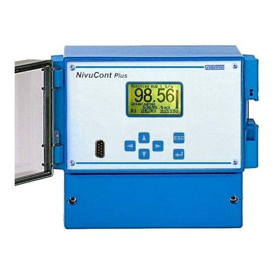
® Instruction Manual NivuCont Plus Overview and use in accordance with the requirements Overview Display Keypad Terminal Clamp Housing RS232 Interface Fig. 2-1 Overview page 10 Rev. 02 as of 18.02.2009... -
Page 11: Use In Accordance With The Requirements
Ex-Protection The Ex-version of the NivuCont Plus is for power supply of intrinsically safe sen- sors in areas with explosive atmospheres (zone 0/1). The transmitter always has to be installed outside of Ex-zones! -
Page 12: Specifications
® Instruction Manual NivuCont Plus Specifications Transmitter Power supply 85 - 264 V AC, 50 - 60 Hz or 18 - 36 V DC (stabilized) Power consumption max. 10 VA Wall mount enclosure Material: Polycarbonate / on-site enclosure, wall mount and DIN rail mount, Weight: - wall mount approx. -
Page 13: General Notes On Safety And Danger
All operations, which go beyond steps regarding installation, connection or pro- gramming the unit are allowed to be carried out by NIVUS staff only due to rea- sons of safety and guarantee. 3.1.2... -
Page 14: Device Identification
® Instruction Manual NivuCont Plus Device Identification The instructions in this manual apply only for the type of device indicated on the title page. The nameplate is fixed on the on the bottom of the device and con- tains the following:... -
Page 15: User's Responsibilities
Before operating the device the user has to ensure, that the local regulations (e.g. for electric supply) on installation and initial start-up are taken into account, if this is both carried out by the user. NivuCont Plus - Rev. 02 as of 18.02.2009 page 15... -
Page 16: Functional Principle
NivuCont Plus Functional Principle General The NivuCont Plus is a multifunctional process measurement transmitter capa- ble to supply several 2 or 3-wire sensors. Computer options as well as links be- tween the inputs concerning comparison, average value, total, linearization, cal- culation of exponential functions and volume are possible. -
Page 17: Storing, Delivery And Transport
Transportation must be carried out in the original packaging. Return The units must be returned at customer cost to NIVUS Eppingen in the original packaging. Otherwise the return cannot be accepted! NivuCont Plus - Rev. -
Page 18: Installation
For electric installation the local regulations in the respective countries (e.g. VDE 0100 in Germany) must be referred to. The NivuCont Plus power supply must be separately protected by a 6 A slow- blow fuse and has to be isolated from other facility parts (separate turn-off, e.g. -
Page 19: Enclosure Dimensions
The transmitter is available in 2 different enclosures - on-site enclosure (wall/DIN rail mounting) or 19“-unit. 239 (9.41in) 213 (8.39in) 118.2 (4.65in) 5.3 (0.21in) 8 (0.31in) 5.3 (0.21in) 198 (7.8in) Fig. 6-1 Wall Mount Enclosure Type VB NivuCont Plus - Rev. 02 as of 18.02.2009 page 19... -
Page 20: Transmitter Installation
® Instruction Manual NivuCont Plus 72 (2.83in.) 63 (12TE / 2.48in.) 215 (8.46in.) enclosure tubus terminal clamp rail Fig. 6-2 Panel Mount Enclosure Type FB 6.2.3 Transmitter Installation General Please note during installation that electronic components may be destroyed caused by electrostatic bursts. Due to this reason avoid high electrostatic charge by providing proper ground connection. -
Page 21: Transmitter Connection
4 screws. It is not necessary to open the enclosure if the 19”-NivuCont Plus is installed in a rack. It has to be installed in a 19” rack or a 19” frame with 160 mm (6.3 in.) depth by using appropriate guide rails. -
Page 22: Connection Variations
® Instruction Manual NivuCont Plus 6.2.5 Connection Variations Depending on the supply voltage on the mains connections the power supply is 85 to 264 V AC or 24 V DC (see Fig. 6-3 to Fig. 6-5). Attention: in all wiring diagrams for 85 V to 264 V AC power supply use L1, N and PE as description (such as e.g. -
Page 23: Input Configuration
Fig. 6-5 Connection 19“-Unit Input Configuration The NivuCont Plus is able to supply up to two 2-wire or 3-wire sensors with a de- fined voltage. These different input signals or sensor inputs absolutely have to be defined be- fore electric connection (see chapter 6.2.4). -
Page 24: Board On-Site Enclosure
® Instruction Manual NivuCont Plus Fig. 6-6 Board 19“-Unit Fig. 6-7 Board on-site Enclosure page 24 Rev. 02 as of 18.02.2009... -
Page 25: Connection Examples
NivuCont Plus (label with the article num- ber, see Fig. 4-1). Example 1: NivuCont Plus with analog output 1 and 2-wire sensor supply; with error mes- sage relay. Fig. 6-8 Connection Example NCP with 2-wrie Sensor... -
Page 26: Fig
® Instruction Manual NivuCont Plus Example 3: 2-channel device with 2 analog outputs and 2-wire sensor supply (2 pcs.), error message relay. Fig. 6-10 Connection Example NCP 2-channel with 2x 2-wire Sensor Example 4: 2-channel device with one analog output, relay Fig. -
Page 27: Overvoltage Protection
NivuCont Plus will put out an error message). EnerPro 220 Tr for 230 V power supply of the NivuCont Plus. Leakage cur- rent 20.000 A and high capacity (up to 16 A) for safe and durable protection of several devices simultaneously. -
Page 28: Overvoltage Protection Of Analog Outputs
® Instruction Manual NivuCont Plus Fig. 7-2 Overvoltage Protection of analog Outputs Fig. 7-3 Overvoltage Protection of Power Supply Please observe the non-reversed connection of the DataPro (p-side to trans- mitter) as well as a correct, straight wiring supply. Ground (earth) must lead to the unprotected side. -
Page 29: Initial Start-Up
The operation of the NivuCont Plus is such that unfamiliar users are able to carry out all fundamental tasks for easy and safe operation of the device thanks to the help of the graphic dialog menu. -
Page 30: Display And Control Elements
Fig. 8-1 Front View 19“/FB-Version 8.2.1 Display The NivuCont Plus has a large back-lit graphic display with a resolution of 128 x 64 pixel. This ensures a comfortable communication mode for the user. Description (main screen) Unit (main screen) Measurement value (main screen) Fuellstd.Becken... -
Page 31: Navigation Keys
RUN menu press once; toggle from RUN menu to overview menu (main menu) activate a submenu Enter accept and store values, units and so on NivuCont Plus - Rev. 02 as of 18.02.2009 page 31... -
Page 32: Parameter Setting
® Instruction Manual NivuCont Plus Parameter Setting Brief Description of the single Basic Menus There are 5 basic menus which can be selected separately. The menu selection is indicated below. This selection depends on the type of device! Display in Operation... -
Page 33: Description Of Par Submenus
This menu serves to determine settings such as the baud rate in order to define the data transfer velocity between transmitter and PC. Communication is car- ried out via software installed on the PC and an accompanying cable via RS 232 interface. NivuCont Plus - Rev. 02 as of 18.02.2009 page 33... -
Page 34: Rs232 Interface - Pin Wiring
Function: It is possible to transmit and to store all parameters in via a zero modem cable in text format from the NivuCont Plus to a PC and vice versa. PC requirements: Terminal program installed on the PC, e.g. Windows® Hyper Terminal pro- gram. -
Page 35: Download And Store Nivucont Plus Parameters
® Instruction Manual NivuCont Plus 9.1.2 Download and store NivuCont Plus parameters Fig. 9-5 Start of Terminal Program Fig. 9-6 Name of the Connection NivuCont Plus - Rev. 02 as of 18.02.2009 page 35... -
Page 36: New Connection Terminal Program
® Instruction Manual NivuCont Plus Fig. 9-7 New Connection Terminal Program Fig. 9-8 COM 1 – Connection Settings page 36 Rev. 02 as of 18.02.2009... -
Page 37: Record File - Search Path
Record File – Search Path Use „Browse“ to select the path in which the parameter file is to be stored. Fig. 9-11 Hyper Terminal – Select File to be Recorded NivuCont Plus - Rev. 02 as of 18.02.2009 page 37... -
Page 38: Fig
Save file name (example “Test”) in this example (in test folder “RS232 TEST” saved before). Fig. 9-12 Hyper Terminal – Record File Use „Start“ in order to open the connection to the NivuCont Plus if path and file name are correct. Fig. 9-13 Hyper Terminal – Parameter Transmission Start the NivuCont Plus parameter transmission under main menu “Interface”... - Page 39 Stop text recording after successful transmission, the file now is saved in the se- lected folder (Fig. 9-10). Fig. 9-15 Hyper Terminal – Editor It is possible to open the parameter file at any time by using the Editor. NivuCont Plus - Rev. 02 as of 18.02.2009 page 39...
- Page 40 ® Instruction Manual NivuCont Plus Fig. 9-16 Hyper Terminal – modify parameters The parameters each can be modified, saved and sent back to the NivuCont Plus if required. Fig. 9-17 Hyper Terminal – ASCII Configuration page 40 Rev. 02 as of 18.02.2009...
- Page 41 Confirm the selected ASCII configuration with OK! Then set the NivuCont Plus via the main menu „Interface“ to the submenu „Receive Parameters“ and confirm with Enter. The NivuCont Plus now is ready to receive parameters from the PC. NivuCont Plus - Rev. 02 as of 18.02.2009...
-
Page 42: Upload Parameters From Pc To Nivucont Plus
® Instruction Manual NivuCont Plus 9.1.3 Upload Parameters from PC to NivuCont Plus Fig. 9-19 Hyper Terminal – send Text file Fig. 9-20 Hyper Terminal – select Text file page 42 Rev. 02 as of 18.02.2009... -
Page 43: Fig
Fig. 9-21 Hyper Terminal – transferred Text file After the parameters have been sent to the NivuCont Plus successfully the de- vice generates the message “Parameters received – End of Transmission” and jumps back to the submenu “Receive parameters”. -
Page 44: Parameter Setting Principles
® Instruction Manual NivuCont Plus Fig. 9-23 Sensor Calibration You have the option to carry out a 1-point calibration for the 4 mA value (zero point) or the 20 mA value (final measurement value), if it is possible to physically provide the water column for the 20 mA point. - Page 45 Faulty entering the code causes the parameter mode to abort and the device operates with the values set before. If the code is entered correctly the modified parameters will be accepted. NivuCont Plus - Rev. 02 as of 18.02.2009 page 45...
-
Page 46: Parameter Menu (Par)
All additional functions are extensions which are required in special cases only. Normally the setup is carried out by our initial start-up service. Almost all NivuCont Plus programming options are listed. Under certain cir- cumstances some inputs and outputs are not realized as hardware and hence may be programmable but cannot be used however. -
Page 47: Parameter Menu „Settings
Instruction Manual NivuCont Plus 9.3.1 Parameter Menu „Settings“ This menu indicates the NivuCont Plus basic settings and is required for pa- rameter setting. The following submenus are available: Fig. 9-27 Submenu Settings This menu allows to modify or to reset the basic system settings below. -
Page 48: Parameter Menu „Analog Input
® Instruction Manual NivuCont Plus In order to enter the PIN-Code please proceed as follows: There is a cursor below >0< which can be activated by pressing the „up“ and „down“ arrow keys. Pressing the „arrow up“ key will increase the respective value by one step (1). -
Page 49: Fig
The value in the selected unit which will be added to or subtracted from the measured value and indicated on the display. This value will be subtracted if entered with a minus sign. NivuCont Plus - Rev. 02 as of 18.02.2009 page 49... -
Page 50: Parameter Menu „Measurement Values 1-3
® Instruction Manual NivuCont Plus 9.3.3 Parameter Menu „Measurement Values 1-3“ This section enables to set the functions of the single measurement values 1 to 3 (input direct, linearization 1 + 2, calculation exp. formula) Fig. 9-35 Function Selection of Measurement Values Fig. -
Page 51: Fig
AI 1. This input has a measurement range of 6 m, but the customer wishes the bargraph to fully swing at 4 m. In this case set 4.0000 as 100 % value. NivuCont Plus - Rev. 02 as of 18.02.2009 page 51... -
Page 52: Damping
® Instruction Manual NivuCont Plus Fig. 9-41 Damping Damping The input signal damping is set to 2 seconds by default. It can be increased up to max. 10 seconds. Fig. 9-42 Modifying decimal Digits Decimal Position The default setting for the decimal digits is 2. -
Page 53: Fig
This value will be added to or subtracted from the nominal value. Fig. 9-47 Entering the Number of Break Points Number of Points It is possible to enter up to 16 break points (value pairs, current/nominal). NivuCont Plus - Rev. 02 as of 18.02.2009 page 53... -
Page 54: Selecting The Input Value
® Instruction Manual NivuCont Plus Fig. 9-48 Selecting the Input Value Input Value 1 The first current value of the input reference (normally AI 1 with the respective unit) must be entered here. Fig. 9-49 Selecting the Output Value Output Value 1 The first nominal value of the measurement value after linearization including the measurement unit must be entered here. -
Page 55: Fig
In case of a flume the offset = 0! The unit will be taken from the assigned analog input respectively. NivuCont Plus - Rev. 02 as of 18.02.2009 page 55... -
Page 56: Stormwater Basin With Overflow
® Instruction Manual NivuCont Plus Calculation via Exponential Function using the Example of Overflow Meas- urement AI1 value at 20 mA (P113) h-max Exp-Function (P383) Offset (P381) Q-max Exp-Function (P384) Overfall Fig. 9-54 Stormwater Basin with Overflow Fig. 9-55 Selecting the Q max. Exponential Function Q-max. -
Page 57: Parameter Menu „Measurement Value 4
Fig. 9-58 Selecting the calculated Allocation Allocation (calcu- Second Measurement of the link (of measurement value 4). lated) Units will be taken from the assigned analog input of the respective value. NivuCont Plus - Rev. 02 as of 18.02.2009 page 57... -
Page 58: Parameter Menu „Display
® Instruction Manual NivuCont Plus 9.3.5 Parameter Menu „Display“ This menu defines the display screen. Fig. 9-59 Selection Options Measurement Values 1-4 Main Screen The main screen for display 2 can be activated if necessary (measurement values 1-4, too) Fig. 9-60 Selecting the Additional Screen Fig. -
Page 59: Parameter Menu „Relay
Relay Function „Trend AI, Basin Purification“ active only if soft- ware extension „B“ or „K“ was ordered (see page 16, Fig. 4-1). Fig. 9-66 Overview Relay Functions – Part 2 NivuCont Plus - Rev. 02 as of 18.02.2009 page 59... -
Page 60: Selection Of Limit Level
® Instruction Manual NivuCont Plus Fig. 9-67 Selection of Limit Level Limit Level Fig. 9-68 Selecting the Relay Allocation Allocation The relays can be assigned to the single measurement values 1-4. If a meas- urement value has a name it will be indicated then instead of „Value X“. -
Page 61: Fig
(e.g. „R1“). Exit this part of the program with ESC thereafter. The modi- fied name is indicated on the display. Please check again and confirm the final modification with the Enter key (see also Fig. 9-37). NivuCont Plus - Rev. 02 as of 18.02.2009 page 61... -
Page 62: Selection „Pump Without Permutation
® Instruction Manual NivuCont Plus Fig. 9-74 Selection „Pump without Permutation“ Pump without Permu- The pumps will be driven according to the preset on/off switch points of the tation relay. Pump cycl. In this case at each on/off cycle the following relay will be used according to the Permutation sequence programmed in permutation mode. -
Page 63: Fig
The limits are 3.3 mA and 22 mA. Menu sequence see see Fig. 9-68 to Fig. 9-73. NivuCont Plus - Rev. 02 as of 18.02.2009 page 63... - Page 64 ® Instruction Manual NivuCont Plus Fig. 9-80 Selection Basin Purification Basin Purification (Option: see type key page 16, software extensions „0B“ or „0K“) The basin purification is active within these bounds and on / off times for the basin purification can be set additionally.
-
Page 65: Parameter Menu „Analog Output
The "off” point of the basin purification is the „switch point -B-“. 9.3.7 Parameter Menu „Analog Output“ Fig. 9-82 Selection of Functions (Main Menu) NivuCont Plus - Rev. 02 as of 18.02.2009 page 65... -
Page 66: Overview Of Functions - Analog Output - Part 1
® Instruction Manual NivuCont Plus Fig. 9-83 Overview of Functions – Analog Output – Part 1 Analog Output 1 Selection 4 -20 mA, 0-20 mA or constant current free selectable. Allocation Here you can assign the outputs to the single measurement values or you can turn them off by setting "not active“. -
Page 67: Parameter Menu „Volume Calculation
No influence on signals or conditions is possible however. It is possible to carry out a simulation only. Due to this reason, this menu mainly serves for assessment and troubleshooting. Fig. 9-87 Overview Inputs/Outputs (Status) NivuCont Plus - Rev. 02 as of 18.02.2009 page 67... -
Page 68: Calibration Menu (Cal)
® Instruction Manual NivuCont Plus Calibration Menu (CAL) Sensor calibration and fine adjustment of analog outputs for following peripher- als. Fig. 9-88 Calibrating the Sensors You can carry out a 1-point calibration for the 4 mA value (zero point) or the 20 mA value (final value of measurement range), if it is possible to physically provide the water column for the 20 mA point. -
Page 69: Fig
>BO< and the total time of the relay being energised – indicating the total overflow time. Even other events such as pump runtimes or similar can be easily indicated this way. NivuCont Plus - Rev. 02 as of 18.02.2009 page 69... -
Page 70: Relay Switch Cylces
® Instruction Manual NivuCont Plus Runtime indication can be modified manually. To do this, select the desired time, confirm your selection with >Enter< and type in the new value. After con- firming the new value using the Enter key enter the PIN code. This PIN code is set to >67<... -
Page 71: Block Diagram Of Nivucont Plus
R elay 1 R elay 2 Total Difference R elay 3 Average Value R elay 4 Multiplication R elay 5 Value 1 Value 2 Value 3 Fig. 9-96 Block Diagram NivuCont Plus - Rev. 02 as of 18.02.2009 page 71... - Page 72 ® Instruction Manual NivuCont Plus Parameter list Example ;Ncplus 38257 0,565474537 ;S/N: 440NCp0001 / T:NC0/AG19ACER10K ;FW Ver NCp 1.00 / FW Date: 23.09.04 / Param. Ver.: 1.00 ;Par.No.Value Description Menu Service Code (default) SETTINGS 2718 code delete Parameter SETTINGS 2718...
- Page 73 Current Value 11 (Lin. 1) Measurement Value 0.0000 Nominal Value 11 (Lin. 1) Measurement Value 0.0000 Current Value 12 (Lin. 1) Measurement Value 0.0000 Nominal Value 12 (Lin. 1) Measurement Value NivuCont Plus - Rev. 02 as of 18.02.2009 page 73...
- Page 74 ® Instruction Manual NivuCont Plus 0.0000 Current Value 13 (Lin. 1) Measurement Value 0.0000 Nominal Value 13 (Lin. 1) Measurement Value 0.0000 Current Value 14 (Lin. 1) Measurement Value 0.0000 Nominal Value 14 (Lin. 1) Measurement Value 0.0000 Current Value 15 (Lin. 1) Measurement Value 0.0000...
- Page 75 Switch Point high Relay (5) 0.0000 Switch Point low Relay (5) Turn-on Delay Relay (5) Turn-off Delay Relay (5) Name Relay (5) not connected Relay (5) not connected Relay (5) NivuCont Plus - Rev. 02 as of 18.02.2009 page 75...
- Page 76 ® Instruction Manual NivuCont Plus Alternative Rel.5 Function Rel.5 (10 = Volume Impulse) Relay (5) not connected Relay (5) not connected Relay (5) 0.0000 not connected Relay (5) 0.0000 not connected Relay (5) not connected Relay (5) not connected Relay (5)
-
Page 77: 10 Troubleshooting
Replace the filter at the box or similar. Moisture in the cable. end of the cable. Check connector box Missing filter on cable end. for leakage. NivuCont Plus - Rev. 02 as of 18.02.2009 page 77... -
Page 78: 11 Programming Example
Writer connected to AO NivuCont Plus 4-20 mA, final swing of writer 20 mA at 8 m. The NivuCont Plus must indicate max. filling level of the container (7 m). The analog input is monitored by an error message relay according to the closed circuit current principle (the relay will release in case of error). -
Page 79: Fig
„mA Input 1“). Then exit this part of the program with ESC. The modified name will be indicated on the display. Please check again and confirm the final modification with the Enter key. NivuCont Plus - Rev. 02 as of 18.02.2009 page 79... -
Page 80: Fig
® Instruction Manual NivuCont Plus It is possible to assign mA in- put 2 to measurement value1. The min. value (0 %) and the Decimal digits of selected value, max. value (max level 100 %) select between 0 (none) and 4... - Page 81 ® Instruction Manual NivuCont Plus Fig. 11-4 Relay Programming NivuCont Plus - Rev. 02 as of 18.02.2009 page 81...
-
Page 82: Rack Difference Measurement
11.2 Rack Difference Measurement 11.2.1 Application Example Rack Control Given: NivuCont Plus with 2x AI and 2x AO as well as 2x relays: Probe 1: 4 – 20 mA, Measurement range 0 – 2 meter Probe 2: 4 – 20 mA, Measurement range 0 – 2 meter... - Page 83 0,5 m - Switch Point A "ON" P524 = 0,05 m - Switch Point B "OFF" P610 = Analog Output 4-20 mA P611 = In This Case - Average Value 4 P612 = P613 = NivuCont Plus - Rev. 02 as of 18.02.2009 page 83...
-
Page 84: 11.2.2 Detailed Parameter Setting Of Rack Difference Measurement
® Instruction Manual NivuCont Plus 11.2.2 Detailed Parameter setting of Rack Difference Measurement: RUN Menu Settings >Analog Input< page 84 Rev. 02 as of 18.02.2009... - Page 85 ® Instruction Manual NivuCont Plus Settings >Analog Input< NivuCont Plus - Rev. 02 as of 18.02.2009 page 85...
- Page 86 ® Instruction Manual NivuCont Plus Settings >Measurement Value< Value 1 – default Value 2 – default Set allocation (y) to Value 2! Set unit for Value 4 to >m<! page 86 Rev. 02 as of 18.02.2009...
- Page 87 ® Instruction Manual NivuCont Plus Settings >Display< Settings >Relays< NivuCont Plus - Rev. 02 as of 18.02.2009 page 87...
- Page 88 ® Instruction Manual NivuCont Plus Settings >Relays< page 88 Rev. 02 as of 18.02.2009...
- Page 89 ® Instruction Manual NivuCont Plus Settings >Analog Output< NivuCont Plus - Rev. 02 as of 18.02.2009 page 89...
- Page 90 ® Instruction Manual NivuCont Plus Settings >Analog Output< Parameter acceptance and storage After setting application specific parameters, please confirm with ENTER Display Mode Screen mode after parameters Screen mode after parameters for measurement value 2 for measurement value 1 have been set...
-
Page 91: Overflow Measurement
Overflow Measurement 11.3.1 Application Example Overflow Measurement Given: NivuCont Plus with 1 x AI and 1 x AO as well as 2x relays volume measurement: Probe: Measurement range 0-2 m, overflow level above sill 10 cm, Q/h characteristic available (height of sill 1.5 m) -
Page 92: 11.3.2 Detailed Parameter Setting Of An Overflow Measurement
® Instruction Manual NivuCont Plus NCP Application Overflow Measurement Short Parameter List; Type: NCP- 12VAAC0R00M P110 = 1 (4- 20 mA) P111 = 0 P112 = 0 P113 = 2 P210 = 4 ( calculation exponent) value 1 P214 = 6... - Page 93 ® Instruction Manual NivuCont Plus Settings >Analog Input< NivuCont Plus - Rev. 02 as of 18.02.2009 page 93...
- Page 94 ® Instruction Manual NivuCont Plus Settings >Measurement Value< reduce from 2 decimal digits to 1 since l/s is selected for over- flow determination. page 94 Rev. 02 as of 18.02.2009...
- Page 95 = 1.6 m) The calculated value has to be For selecting Exponent values entered here refer to the hints under Fig. 9-53 for according applications Settings >Measurement Value< NivuCont Plus - Rev. 02 as of 18.02.2009 page 95...
- Page 96 ® Instruction Manual NivuCont Plus The auxiliary indicator “total“ is required in order to indicate the cumulated volume in addition to the current overflow Settings >Relays< page 96 Rev. 02 as of 18.02.2009...
- Page 97 ® Instruction Manual NivuCont Plus Settings >Relays< Settings >Analog Output< NivuCont Plus - Rev. 02 as of 18.02.2009 page 97...
- Page 98 ® Instruction Manual NivuCont Plus Settings >Analog Output< Settings >Volume Calculation< page 98 Rev. 02 as of 18.02.2009...
- Page 99 1m³ proceeding to count the total volume. Relay 2 is greyed out as long as it is active because an overflow event happens right now (begin of overflow). NivuCont Plus - Rev. 02 as of 18.02.2009 page 99...
-
Page 100: Basin Purification Control
Instruction Manual NivuCont Plus 11.4 Basin Purification Control Given: NivuCont Plus with 2x relay, 1x analog input, 1x analog output and software for basin purification Probe : 4-20 mA, measurement range 0-4 m Required: Basin purification shall be released in case of decreasing trend (draining basin / stormwater overflow tank) using interval mode. - Page 101 (4-20 mA) P612 = 0 P613 = 4 11.4.2 Detailed Parameter setting of a Basin Purification Control via 1 Relay: RUN Menu Settings >Analog Input< Toggle from “mA“ to “m“ NivuCont Plus - Rev. 02 as of 18.02.2009 page 101...
- Page 102 ® Instruction Manual NivuCont Plus Settings >Analog Input< define value for 4 mA point confirm value (0.000 m) define value for 20 mA-point change value to 4 m confirm value (4.0000 m) page 102 Rev. 02 as of 18.02.2009...
- Page 103 ® Instruction Manual NivuCont Plus Settings >Relays< set relay 1 Switch points A and B define active band for basin purifica- tion NivuCont Plus - Rev. 02 as of 18.02.2009 page 103...
- Page 104 ® Instruction Manual NivuCont Plus Settings >Relays< Add ”B“ for basin purification change name of relay 1 and confirm accept changes! Recommended value (180 sec) Define off-time for basin purifi- Recommended value (60 sec) cation control interval page 104 Rev. 02 as of 18.02.2009...
- Page 105 (to pre- vent relay from “flashing“) Basin purification control shall be active in case of falling water level (trend) Switch-off point shall be at a rising water level of 0.02 m NivuCont Plus - Rev. 02 as of 18.02.2009 page 105...
- Page 106 ® Instruction Manual NivuCont Plus Settings >Relays< The basin purification unit (jet pump) will run at decreasing trend in continuous operation mode (-B-) until reaching the switch-off point if the value falls below this threshold set relay page 106 Rev. 02 as of 18.02.2009...
- Page 107 ® Instruction Manual NivuCont Plus Settings >Relays Settings >Analog Output< NivuCont Plus - Rev. 02 as of 18.02.2009 page 107...
- Page 108 ® Instruction Manual NivuCont Plus Parameter acceptance and storage After setting application specific parameters, please confirm with ENTER Display menu Relay 1 “R1B” is greyed out for Screen after programming basin purification since trend indication is active page 108 Rev. 02 as of 18.02.2009...
-
Page 109: 12 Maintenance And Cleaning
In various countries it may be necessary to carry out regular maintenance with comparative measurements in particular applications to comply with official regu- lations. If desired, NIVUS takes the job to do all necessary checks, hydraulic and technical assessment, calibrations, troubleshooting and repairs according to an eventual maintenance contract. -
Page 110: 13 Emergency
The device has to be disposed according to the local regulations for electronic products. 15 Table of Pictures Fig. 2-1 Overview ............................10 Fig. 4-1 Type key for NivuCont Plus measurement transmitter ..............16 Fig. 6-1 Wall Mount Enclosure Type VB ....................19 Fig. 6-2 Panel Mount Enclosure Type FB ....................20 Fig. 6-3 Connection Enclosure Type „VB“... - Page 111 Limiting the Number of Pumps.....................62 Fig. 9-77 Selection in bound function......................63 Fig. 9-78 Entering Hysteresis ........................63 Fig. 9-79 Selection Fault Input ........................63 Fig. 9-80 Selection Basin Purification ......................64 Fig. 9-81 Setting the “on-time”........................64 NivuCont Plus - Rev. 02 as of 18.02.2009 page 111...
- Page 112 ® Instruction Manual NivuCont Plus Fig. 9-82 Selection of Functions (Main Menu) ....................65 Fig. 9-83 Overview of Functions – Analog Output – Part 1.................66 Fig. 9-84 Selection Error Monitoring ......................66 Fig. 9-85 Overview of Functions – Analog Output – Part 2.................66 Fig.
Need help?
Do you have a question about the NivuCont Plus and is the answer not in the manual?
Questions and answers