Nivus NivuFlow 600 Instruction Manual
Flow measurement transmitter
Hide thumbs
Also See for NivuFlow 600:
- Instruction manual (149 pages) ,
- Instruction manual (125 pages) ,
- Instruction manual (194 pages)
Table of Contents
Advertisement
Quick Links
F L O W p e r m a n e n t
Instruction Manual
Flow Measurement Transmitter
NivuFlow 600
Firmware Revision: 2.3.X
Revised manual
Document revision: rev. 03 / 22.10.2019
Original Manual: German / rev. 03 as of 25.09.2019
I n s t r u m e n t a t i o n
f o r
W a t e r
I n d u s t r y
NIVUS GmbH • Im Taele 2 • Germany-75031 Eppingen • Internet: www.nivus.com
Phone +49 (0) 7262 9191-0 • Fax +49 (0) 7262 9191-999 • E-Mail: info@nivus.com
Advertisement
Table of Contents

Related Manuals for Nivus NivuFlow 600


Summary of Contents for Nivus NivuFlow 600
- Page 1 W a t e r I n d u s t r y NIVUS GmbH • Im Taele 2 • Germany-75031 Eppingen • Internet: www.nivus.com Phone +49 (0) 7262 9191-0 • Fax +49 (0) 7262 9191-999 • E-Mail: info@nivus.com...
- Page 2 Yeon-su-gu, www.nivus.de INCHEON, Korea 21984 Phone +82 32 209 8588 Fax +82 32 209 8590 korea@nivus.com NIVUS Sp. z o.o., Poland www.nivus.com ul. Hutnicza 3 / B-18 81-212 Gdynia, Poland Phone +48 (0)58 7602015 Fax +48 (0)58 7602014 NIVUS Vietnam biuro@nivus.pl...
-
Page 3: Copyrights And Property Rights
Copyrights and property rights Copyrights and property rights This document and its contents are proprietary to NIVUS GmbH and are not to be reproduced or copied without the express written permission of NIVUS GmbH. Violations will be liable for compensation. -
Page 4: Document Modifications
Instruction Manual NivuFlow 600 Document modifications Rev. Modifications Editor in Date charge Complete revision: many features and functions added, layout redesi- 22.10.2019 gned etc. Section “33.4 Alignment” modified 27.02.2019 Minor modifications; no approval 25.04.2016 First version based on the German document 21.12.2015... -
Page 5: Table Of Contents
Contents Contents COPYRIGHTS AND PROPERTY RIGHTS DOCUMENT MODIFICATIONS GENERAL About this manual ..................11 Applicable documentation ................. 11 Signs and definitions used ................12 Abbreviations used .....................12 Connections and Operating Elements ..........12 Power Supply .....................12 NivuFlow Operating Elements ................13 Tasks of control elements ...................13 Interfaces ......................14 SAFETY INSTRUCTIONS General: Used Symbols and Signal Words ........... - Page 6 Instruction Manual NivuFlow 600 PRODUCT SPECIFICATION 15 Product Construction and Overview ............. 21 15.1 Dimensions of enclosure ..................22 15.2 Connectable sensors ..................23 15.3 Device identification ..................23 16 Specifications ..................24 17 Configuration ..................26 17.1 Device Types .....................26 FUNCTIONAL DESCRIPTION 18 Operating Ranges ..................
- Page 7 Contents 23.3 Overvoltage protection for communication interfaces ........50 23.4 Overvoltage protection for (transit time) sensor connectors ......51 23.4.1 Basic protection - equipotential bonding cable ..........51 23.4.2 Extended protection - overvoltage protection “SonicPro T” ......51 OPERATION START-UP 24 Notes to users ..................54 25 Operation Basics ..................
- Page 8 Instruction Manual NivuFlow 600 31.1.5 Medium ......................73 31.1.6 Medium Temperature ..................73 31.1.7 Channel Profiles .....................73 31.1.8 Wall Material ....................74 31.1.9 Lining ......................74 31.1.10 Sludge Level ....................75 31.1.11 3D-Preview .....................75 31.1.12 Flow velocity analysis ..................75 31.1.13 Low-Flow Suppression ...................75 31.1.14 Damping ......................76 31.1.15 Stability ......................76...
- Page 9 Contents 33.5 Service ......................102 33.5.1 Service Level ....................103 33.5.2 Change (System) Password .................103 33.5.3 Reboot ......................103 33.5.4 Restart Measurement ...................104 33.5.5 Parameter reset ....................104 33.5.6 Update NivuFlow ..................104 34 Communication Parameter Menu ............105 35 Display Parameter Menu ............... 107 36 Connections Parameter Menu .............
- Page 10 Instruction Manual NivuFlow 600 MAINTENANCE AND CLEANING 44 Maintenance ................... 133 44.1 Maintenance Interval ..................133 44.2 Customer Service Information ................133 45 Cleaning ....................134 45.1 Transmitter .......................134 45.2 Sensors ......................134 46 Dismantling/Disposal ................134 47 Installation of spare parts and parts subject to wear and tear ..135 48 Accessories ..................
-
Page 11: General
READ CAREFULLY BEFORE USE. KEEP IN A SAFE PLACE FOR LATER REFERENCE. This instruction manual for the flow measurement transmitter NivuFlow 600 is for the intended use of the device only. This manual is oriented exclusively to qualified expert personnel. -
Page 12: Signs And Definitions Used
Instruction Manual NivuFlow 600 Signs and definitions used Image Meaning Remark (Action) Step Action to be performed by you. Ü Note the numbering of action steps. Observe the order of the steps. Cross-reference Refers to further or detailed information. >Text<... -
Page 13: Nivuflow Operating Elements
General NivuFlow Operating Elements The NivuFlow is operated completely in dialogue mode supported by the graphs on the display. To select individual menus and submenus use the rotary pushbutton as well as both function keys. Graphic display Left function key Rotary pushbutton Right function key Fig. -
Page 14: Interfaces
Instruction Manual NivuFlow 600 Diagnostics of the signal analysis ƒ • Menu >Data< Selection of Trend, Total and Day totals ƒ Within the programming of multiple inputs/outputs or when programming several v-paths, the right function key is used to jump from one input/output or v-path to the next. -
Page 15: Safety Instructions
Safety Instructions Safety Instructions General: Used Symbols and Signal Words Valuation of the accident level The general warning symbol indicates the risk of personal injuries or death. In the text section the general warning symbol is used in conjunction with the signal words described below. -
Page 16: Warning Notices On The Product (Option)
Integrated buffer battery The integrated buffer battery may only be exchanged by NIVUS staff or personnel authori- sed by NIVUS. Infringements lead to a limitation of the warranty (see Sect. “5 Warranty”). page 16 NF 600 - rev. 03 / 22.10.2019... -
Page 17: Warranty
Limitation of warranty In the event of non-compliance with the safety instructions and instructions in this document, the companies of the NIVUS group of companies reserve the right to limit the warranty. Liability Disclaimer The legally associated companies and subsidiaries of NIVUS group assume no liability •... -
Page 18: Use In Accordance With The Requirements
The user alone bears any risk. The NivuFlow 600 transmitter and associated sensor system is designed for continuous flow measurement of slightly contaminated to clear, pure water-based liquids in fully filled pipes (round and rectangular). -
Page 19: Personnel Requirements
Safety Instructions Personnel requirements Installation, commissioning and maintenance shall be executed only by personnel meeting the demands as follows: • Expert personnel with relevant training and appropriate qualification • Personnel authorised by the plant operator Qualified personnel within the context of this documentation or the safety notes on the product itself are per- sons who are sufficiently familiar with installation, mounting, starting up and operation of the product and who have the relevant qualifications for their work;... -
Page 20: Delivery, Storage And Transport
Otherwise, the same rules apply with regard to external influences as for storage (see Sect. “12 Storage”). 14 Return In case of a required reshipment return the unit at customer cost to NIVUS GmbH in Eppingen using the original packaging. Insufficiently franked shipments will not be accepted! page 20 NF 600 - rev. -
Page 21: Product Specification
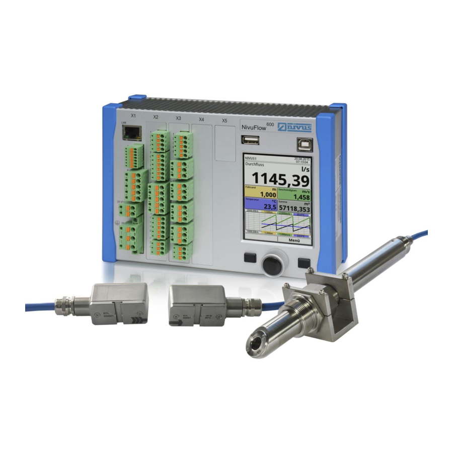
USB-A interface (data transfer, parameter backup, device update) USB-B interface (service) Graphics display Left function key Rotary pushbutton Right function key DIN rail fastening Fig. 15-1 Device setup NivuFlow 600 enclosure type E0/E1 NF 600 - rev. 03 / 22.10.2019 page 21... -
Page 22: Dimensions Of Enclosure
Instruction Manual NivuFlow 600 15.1 Dimensions of enclosure Fig. 15-2 Dimensions of NivuFlow 600 enclosure type E0 Fig. 15-3 Dimensions of field enclosure NivuFlow page 22 NF 600 - rev. 03 / 22.10.2019... -
Page 23: Connectable Sensors
Product specification 15.2 Connectable sensors You can find the connectable NIVUS sensors and their data or information on their mounting in the documents “Technical Instructions Transit Time Sensors” and “Installation Instructions Transit Time Sensors”. These documents are delivered with the ordered sensors. Alternatively, they are available for download at www.nivus.com. -
Page 24: Specifications
Instruction Manual NivuFlow 600 Fig. 15-5 Nameplate DC version 16 Specifications Power supply 100...240 V AC, -15 % / +10 %, 47...63 Hz or 10...35 V DC Supply connection Plugged and screwed tension clamp terminal block Max. power consumption AC: 30 VA / DC: 20 W Typ. - Page 25 Product specification Inputs Digital input: - electrically isolated 5...24 V nominal, input current typically < 5 mA for max. input voltage U =30 V, input current typically > 1.5 mA for min. input voltage U =3 V Analog input: - 4 mA…20 mA with 12 bit resolution for analog input values, accuracy ±0.4 % of measuring range final value (20 mA), load 91 Ohm Outputs Digital output:...
-
Page 26: Configuration
DIN rail/panel mounting (cabinet) T2E1 up to 2 acoustic paths, 2x DI, 2x DO, 2x AI, 2x AO; DIN rail, prepared for mounting into NIVUS field enclosure, Type ZUB0 NFW0 TRE0 up to 2 acoustic paths, 7x DI, 5x DO, 5x AI, 4x AO;... -
Page 27: Functional Description
The NivuFlow 600 is used in fully filled channels and pipes of various geometries and dimen- sions. The two points of measurement of types T4 and TM are primarily used to carry out measure- ments at two different points within a channel. -
Page 28: Functional Principle
There is no measurable flow available. The NivuFlow 600 works with both clamp-on sensors and wetted sensors. The clamp-on sen- sors are installed on the outside of the pipe. In this case the transit time through the pipe wall is calculated and considered. -
Page 29: Flow Calculation
Functional Description cross-section, the more accurately the flow can be determined. Sensor 1, path 1 Sensor 2, path 1 Sensor 1, path 2 Sensor 2, path 2 Pipe diameter (at sensor installation in an angle of 45°) Fig. 19-2 Two-path transit time measurement principle If the sensors are installed in an angle of 45°, the distance between sensors 1 and 2 or sen- sors 3 and 4 is equal to the inside pipe diameter. -
Page 30: Installation And Connection
NivuFlow 600 Type E0 not suitable for installation in NIVUS field enclosure It is not possible to install a NivuFlow 600 Type E0 in a NIVUS field enclosure unless the transmitter is converted to a Type E1 unit. The conversion and the modification of connec- tions can be carried out by NIVUS. -
Page 31: Choosing The Installation Place
Make sure that any existing disconnectors (power switch) remain easily accessible during installation. The measurement transmitter can also be installed in field enclosures or similar. NivuFlow 600 is not suitable to be installed directly on site without protective measures due to protection class. -
Page 32: Field Enclosure Fastening And Preparing Electric Installation
The fastening material is not part of the standard delivery but should be specified and chosen individually depending on the place of installation. The NIVUS field enclosure can be installed permanently once the appropriate place of installa- tion has been chosen. A basic condition is safe, durable and stable installation. - Page 33 Readability may be strongly impai- red due to the changes to the protective film. New clear view covers can be purchased from NIVUS for an extra charge and can be easily replaced by the user.
-
Page 34: Electrical Installation
Instruction Manual NivuFlow 600 21 Electrical Installation DANGER Danger from electrical current Disconnect the unit from mains power. Working on electric wiring may cause electric shock. Observe electric information provided on the nameplate. Non-observance may result in personal injuries. Note Observe the national installation regulations. - Page 35 [mm²] 0.25...2.5 Wire cross-section (flexible) with ferru- 0.25...2.5 Undefined 0.25...0.5 le with plastic sleeve in [mm²] Table 21-1 Wire cross-section The measurement transmitter NivuFlow 600 is available in different Types: • Type T2 • Type TR • Type T4 • Type TM •...
-
Page 36: Plans Of Terminal Connections
Operate the instrument with the tension clamp terminal block screwed on only. Non-observance may result in personal injuries. Fig. 21-2 Terminal connections NivuFlow 600 Type T2 page 36 NF 600 - rev. 03 / 22.10.2019... - Page 37 Installation and Connection Fig. 21-3 Terminal connections NivuFlow 600 Type TM NF 600 - rev. 03 / 22.10.2019 page 37...
- Page 38 Instruction Manual NivuFlow 600 Fig. 21-4 Terminal connections NivuFlow 600 Type T4 page 38 NF 600 - rev. 03 / 22.10.2019...
- Page 39 Installation and Connection Fig. 21-5 Terminal connections NivuFlow 600 Type TR NF 600 - rev. 03 / 22.10.2019 page 39...
- Page 40 Instruction Manual NivuFlow 600 Fig. 21-6 Terminal connections NivuFlow 600 Type TZ page 40 NF 600 - rev. 03 / 22.10.2019...
-
Page 41: Switching On Voltage Supply
Installation and Connection 21.3 Switching on voltage supply Depending on the type of NivuFlow used the unit can be powered with 100...240 V AC (-15 / +10 %) or with 10...35 V DC. 24 V DC connection 230 V AC connection Fig. -
Page 42: Power Supply Ac
Instruction Manual NivuFlow 600 21.3.2 Power supply AC DANGER Danger from electrical current Do not operate the unit if the terminal clamp blocks above the screw flange are not tightly screwed. The terminal block X1 (terminals 15...17) for connecting the earth conductor and AC power supply is an integral part of the device. -
Page 43: Relays
Installation and Connection 21.4 Relays Contact reliability deteriorates if the minimum make/break current is lower than specified. Observe the wiring and switching specifications of the relays in Sect. “16 Specifica- tions”. DANGER Danger from electrical current – Measures to prevent accidental contacts Contact protection according to the requirements as specified in EN 61010-1:2010 is not guaranteed in the event of relay voltages >150 V due to the testing pin terminal of the relay clamp blocks. -
Page 44: Installation Of Clamp-On Sensors
Instruction Manual NivuFlow 600 22.2 Installation of Clamp-On Sensors Clamp-on sensors allow for contactless measurement in closed and full pipelines. Here the sensors are clamped from the outside onto pipes. The instrumentation will not impact the liquid and will not change the medium's flow profile. -
Page 45: Cable And Cable Length For Connecting The Sensors
The cables connected to the sensors at the factory must be used for the total distance between the NIVUS sensors and the NivuFlow transmitter. The signal cable is not intended for laying directly in the ground. If the signal cable is to be laid in soil, concrete, etc., it must be laid in protective pipes or protective hoses with a sufficiently... - Page 46 Instruction Manual NivuFlow 600 Connectable clamp-on sensors Fig. 22-5 Connecting 1 pair of clamp-on sensors Connectable flow velocity sensors path 1 Connectable flow velocity sensors path 2 Fig. 22-6 Connecting 2 pairs of flow velocity sensors page 46 NF 600 - rev. 03 / 22.10.2019...
-
Page 47: Connection To/Via Extension Module Nfe
“Technical Instructions for Extension module NFE”. The technical description is shipped with the expansion module and is available for download at www.nivus.com. NF 600 - rev. 03 / 22.10.2019 page 47... -
Page 48: Overvoltage Protection Measures
23.1 Overvoltage Protection for Power Supply NIVUS recommends type EnerPro 220Tr surge arrestors (for a 100-240 V AC power system) and EnerPro 24Tr (for 24 V DC power supply) for the mains supply. Observe the connection direction Observe the non-reversed connection (p-side to transmitter) as well as a correct, straight wiring supply. - Page 49 Installation and Connection 1) Low impulse earthing resistance required Fig. 23-1 Overvoltage protection for power supply AC 1) Low impulse earthing resistance required Do not reverse protected (p) and unprotected sides of overvoltage protection Fig. 23-2 Overvoltage protection for power supply DC NF 600 - rev.
-
Page 50: Overvoltage Protection For Ma-Inputs/Outputs
NivuFlow 600 23.2 Overvoltage Protection for mA-Inputs/Outputs NIVUS recommends type DataPro 2x1 24/24 Tr surge arrestors for mA-inputs and mA-outputs. Observe the connection direction Observe the non-reversed connection (p-side to transmitter) as well as a correct, straight wiring supply. Ground (earth) must lead to the unprotected side. -
Page 51: Overvoltage Protection For (Transit Time) Sensor Connectors
Overvoltage protection for (transit time) sensor connectors 23.4.1 Basic protection - equipotential bonding cable NIVUS recommends that an equipotential bonding cable is used to connect the sensor enclo- sure to the control cabinet/transmitter ground as a basic protection measure for the transit time sensors’... - Page 52 The “EnerPro” overvoltage protector may also be installed inside the control cabinet, but the separate earth connector “G” must be retained. The combination with “P” or “C” is very risky in the event of overvoltage. NIVUS recommends that the earth connectors are separated to guard against overvoltages.
- Page 53 Installation and Connection If it can be assumed in applications that no overvoltages can be induced from the sensor side, there will be no leakage currents through the earth connection “P”. This can then be tied directly to the transmitter grounding “C”. All other input/output signals and input/output voltages leaving the control cabinet must also be considered in relation to overvoltages.
-
Page 54: Operation Start-Up
The user interface of the NivuFlow is easy to understand. Users can make all required basic settings themselves. In the case of the following requirements let either one of the legally associated companies or subsidiaries of NIVUS group or an expert company authorised by NIVUS set the parameters: • Extensive programming tasks •... -
Page 55: Operation Basics
Operation start-up 25 Operation Basics The complete operation of the NivuFlow is handled via control elements (see Sect. “2.2 NivuFlow Operating Elements”). Two control buttons and one rotary pushbutton are available for the setting of parameters and to input required data. The display at any time provides information on where you currently are within the menu struc- ture and which entries you are about to modify. -
Page 56: Use/Entry Using The Letter Block
Instruction Manual NivuFlow 600 The transmitter in the background operates with the settings which have been entered at the beginning of the parameter setting. The following request is prompted on the display not before the current parameter setting has been finished and confirmed. -
Page 57: Use/Entry Using The Numeric Keypad
Operation start-up A shift key can be found at the bottom left of the keypad (Fig. 25-4 no. 3). • The functions of the shift key are: Upper case ƒ Lower case ƒ Special characters ƒ Digits ƒ • These settings allow individual names (e.g. of the measuring place). •... -
Page 58: Revision Of Parameters
• Recall basic information on the transmitter and the connected sen- System sors such as serial no., version, article no. and many more (needed in the event of queries from NIVUS) • Settings such as language, time and data format and units can be modified in the >country settings<... -
Page 59: Measurement With Clamp-On Sensors
Operation start-up 26 Measurement with Clamp-On Sensors Measurements with clamp-on sensors can be carried out very easily and with little effort. The sensors are installed on the outside of the pipe. Prior to the installation of clamp-on sensors the measuring section shall be prepared and the measurement place parameters need to be set. -
Page 60: Measurement With Wet Sensors
Instruction Manual NivuFlow 600 27 Measurement with wet sensors The wetted sensors are installed during the parameterization of the measurement point. Engage pipeline experts Wet sensors shall be installed only by a pipeline company or a plumber. The tightness of pipes must be guaranteed at any time. -
Page 61: Start-Up Examples
Another menu opens up which can be used to specify e.g. the speed of sound within the medium. Tip: Various speeds of sound can be found on the Internet or contact NIVUS GmbH. NF 600 - rev. 03 / 22.10.2019 page 61... - Page 62 Instruction Manual NivuFlow 600 7. Use the selection menu to specify the medium to measure and to select/specify the current medium temperature. 8. Set the channel profile to “Pipe”. The graphics area indicates a pipe featuring input fields. 9. Enter the pipe data (example: DN1000). Two specifications are sufficient to enter the pipe dimensions such as inside diameter and wall thickness in this example.
- Page 63 Sensor Selection and Specification of Mounting Angle procedures: 1. Select menu >v-Paths<. 2. Choose the sensor type used. 3. Enter the mounting angle (NIVUS recommend +45° or -45°) and confirm. Fig. 28-4 Enter the mounting angle (Clamp-on) The >Distance along< field on the display indicates the distance between both sensors.
-
Page 64: Extended Parameter Setting
Instruction Manual NivuFlow 600 28.6.4 Extended Parameter Setting More specifications: • Pipe with inner lining • Sedimentation within the pipe For pipes with inner lining: Ü Â Procedure: 1. Execute steps 1 (“Menu” field, page 61) up to and including 10 (“wall material”;... -
Page 65: Setting Parameters
>Enter< button. The transmitter leaves mode with the parameterization without entering a password. If a number is displayed next to the service key, the transmitter is in service mode. This is usually the case when a NIVUS service technician has access to the transmitter. 29.2 Change Password See also Sect. -
Page 66: Parameter Functions
Instruction Manual NivuFlow 600 30 Parameter Functions 30.1 Main Menu The transmitter parameters can be set using a total of five or eight (for multiple measurement place types) setup menus within the first menu level. Individual menus and their associated submenus are explained in greater detail starting in Sect. -
Page 67: Data Menu
Setting Parameters Within this menu diagnostic options for the items below are available: • Sensors • Inputs and outputs • Complete system • Signal analysis • Simulation The diagnostic options are explained in Sect. “Diagnostics” starting at page 117. Use this menu to enter or change: •... -
Page 68: System Menu
Instruction Manual NivuFlow 600 30.2.3 System Menu Fig. 30-4 System menu The >System< menu contains information on the transmitter: • Article No. • Firmware version • Serial No. Furthermore the settings/adjustments below are available: • Set language • Set units •... -
Page 69: Communication Menu
Details on TCP and Modbus RTU, • Settings for scaling of flow rate, level, velocity, temperature, analog and sum • and there is a diagnostic option (the data available there are important for the NIVUS service). See Sect. “34 Communication Parameter Menu”. 30.2.5 Display Menu Fig. -
Page 70: Connections Menu
Instruction Manual NivuFlow 600 30.2.6 Connections Menu Fig. 30-7 Connections menu This menu is only available for transmitter types T4 and TM, as it deals with the transmitter configuration comprising multiple measurement points. The two DSP cards (digital signal processor cards) and the analog and digital inputs and outputs of the respective measurement points are assigned here. -
Page 71: Active
Setting Parameters Fig. 31-1 Parameter menu application 31.1.1 Active This option is only available for transmitter types T4 and TM, as it deals with the transmitter configuration comprising multiple measurement points. The measurement point is enabled by checking the box. If no check mark is set, the measure- ment point is disabled, nothing is displayed and it cannot be parameterized. -
Page 72: Transit Time Mode
Instruction Manual NivuFlow 600 31.1.3 Transit Time Mode Use >Transit Time Mode< to specify the measurement method. Select from: • Clamp-on (sensors attached from the outside) • Wet (installed sensors with direct medium contact) The appearance of the following menus will vary depending on your choice. In such a case both versions are described in the according section of the respective instruction manual. -
Page 73: Number Of Paths
Setting Parameters 31.1.4 Number of Paths A maximum of four paths can be connected directly. The number of paths can be increased up to 32 by connecting up to four extension modules. Set the number of paths by using “+” and “-”. The number is shown in the text field between both symbols. -
Page 74: Wall Material
This action opens up another menu point which prompts you to specify e.g. the speed of sound of the pipe material. Tip: When it comes to determine the speed of sound within the pipe material contact NIVUS GmbH. 31.1.9 Lining In practice, cases occasionally arise in which pipelines are equipped with inner linings. -
Page 75: Sludge Level
Tip: When it comes to determine the speed of sound within the lining material contact NIVUS GmbH. 31.1.10 Sludge Level Depending on measurement medium and flow velocity, horizontal pipelines may tend to sedi- mentation on the pipe bottom. -
Page 76: Damping
Instruction Manual NivuFlow 600 Fig. 31-6 Low-Flow Suppression The low-flow suppression disregards the detection of very low flow velocity fluctuations. • >Q suppressed<< Enter the flow rate as a positive value. Negative values are not possible. The specified value is considered as absolute value and is effective in both positive and negative directions. -
Page 77: Setting Parameters In Measurement Place Combi Menu
The transmitter shows the sensor mounting distances after the specifications are completed. Up to eight flow rate sensors (4 paths) can be directly connected to a NivuFlow 600 transmit- ter, depending on the type. Up to 64 sensors (32 paths) can be indirectly connected via one or more extension modules (see Sect. -
Page 78: Sensor Types In >Clamp-On< Transit Time Mode
Speed of Sound< must be specified. Specialist knowledge required The use of and settings for non-standard sensors require extensive expert knowledge and require the use of NIVUS commissioning personnel or an authorized specialist company. 31.3.3 Sensor Types in >Wet< Transit Time Mode The same selection of sensors (Fig. -
Page 79: Sensor Mounting Position
The values for >Angle<, >Frequency<, >Offset< must be specified. Specialist knowledge required The use of and settings for non-standard sensors require extensive expert knowledge and require the use of NIVUS commissioning personnel or an authorized specialist company. 31.3.4 Sensor Mounting Position... - Page 80 Instruction Manual NivuFlow 600 • For >Transit Time Mode< “Insertion” and >Path setup< / “Diametral” in >Channel Profile< “Pipe”: >Mounting Angle< ƒ Mounting angle for the sensors in the pipe (based on the cross-section) For >Transit Time Mode< “Insertion” and >Path setup< / “Chordal” in >Channel •...
-
Page 81: Weighting And Hydraulic Factor
The weighting value and the hydraulic factor depend on the application and the sensor position. Such applications require extensive fluid mechanics knowledge and require the use of NIVUS commissioning personnel or an authorized specialist company. • >Weighting< By modifying the >Weighting< value the involved paths can be weighted and prioriti- sed differently. -
Page 82: Analog Inputs
Instruction Manual NivuFlow 600 The inputs/outputs menu is subdivided into four parts: • Analog inputs • Analog outputs • Digital inputs • Digital outputs Note Entry using the letter block see Sect. “25.3 Use/Entry using the letter block”. Operational parameters can only be assigned for a selection of inputs and outputs... -
Page 83: Analog Outputs
Setting Parameters The values below must be chosen/entered in >Flow<. Selection/Input Options: ƒ Input Range: >0-20 mA< or >4-20 mA< Label: manual input Linearisation: >2-Point< or >Table< For >2-Point< linearisation: manual input of values for 4 or 20 mA For >Table< linearisation: manual input of the number of >Entries<, then select >Table<, complete and confirm. -
Page 84: Digital Inputs
Instruction Manual NivuFlow 600 • >Water temperature< The medium temperature calculated based on the transit times is available on the selected analog output. Not for measurement place Combi. Selection/Input Options: ƒ Output range: >0-20 mA< or >4-20 mA< Value at 0/4 mA: manual input Value at 20 mA: manual input Value at error: >0 mA<... - Page 85 Setting Parameters Fig. 31-15 Digital inputs: Activation / Block v-measurement / Impulse counter >Block v-measurement< • The flow measurement can be blocked as long as there is a signal available on the digital input by using an external contact. Not for measurement place Combi. Selection/Input Options: ƒ...
-
Page 86: Digital Outputs
Instruction Manual NivuFlow 600 • >Logging< Logging of readings and the according status changes for diagnostic purposes. Evaluation is carried out by detecting the status changes of the digital input (1->0 or 0->1). Selection/Input Options: ƒ Logic: >not inverted< or >inverted<... - Page 87 Setting Parameters • >Limit contact velocity< If the entered upper velocity limit value is exceeded, a digital signal is output. If the value falls below the lower velocity limit, this digital signal is reset = hysteresis func- tion to avoid output jitter. The calculated mean flow velocity is used (also calculated from several paths).
-
Page 88: Setting Parameters In Diagnostics Menu
Instruction Manual NivuFlow 600 • >Modbus Slave< The digital output can be used via the Modbus for the controlled output of signals from other systems. Selection/Input Options: ƒ Logic: >Normally open< or >Normally closed< 31.5 Setting Parameters in Diagnostics Menu The Diagnostics menu is described separately in greater detail in Sect. - Page 89 Setting Parameters while represented (the current readings can be found in the lower third of the main screen). 2. Use the arrows (Fig. 32-2 no. 7) to browse next or back if required leaving the basic display settings unaltered. 3. In order to get back to the main screen press the left function (Back) three times. The Date/Time Selection (Fig.
- Page 90 Instruction Manual NivuFlow 600 If period >4 hours< is chosen the start of the representation depends on the selected point of time. Depending on the start time the representation begins: • 00:00 h • 04:00 h • 08:00 h •...
-
Page 91: Total
Setting Parameters 32.2 Total The totals, divided into positive and negative totals, for the respective measurement points are displayed. In addition, the resettable totals are displayed and they can also be reset using the >Reset total< button. The individual measurement points are shown at the top right of the display. You can scroll between the measurement points with the Tab key. - Page 92 Instruction Manual NivuFlow 600 In general, only totals created during days with the transmitter actually powered up can be viewed. If the transmitter should be shut down between two totalising events (< 24 hours) a total will be calculated by using measured values. Such a total is not equal to the real daily flow rate but corresponds to the rate measured by the transmitter while powered up.
-
Page 93: Usb Stick
Setting Parameters 32.4 USB stick Requirements to USB sticks: • USB 2.0 supported • FAT 32 format (or FAT 12 or FAT 16) • Maximum permissible memory 32 GB Working with USB stick: Ü Â Plug the USB stick into the USB slot located above the display. Functions: •... - Page 94 Instruction Manual NivuFlow 600 Fig. 32-7 Transmission period / data depth / compression 9. To choose the desired data format turn the rotary pushbutton which opens a selec- tion menu. The formats txt and csv are available. 10. Press the rotary pushbutton to accept the data format.
- Page 95 Setting Parameters • Operating hours This option saves only the operating hour totals, no individual values. The >Compress< function makes sense only when large data sets are to be transmitted. In such cases the selected files are zipped as “.zip” files. If the check mark is set, you can also select >Ram<...
-
Page 96: Data Storage
Instruction Manual NivuFlow 600 Ü Â You can convert unformatted or incorrectly formatted USB sticks into the correct format directly on the instrument: 1. Turn the rotary pushbutton until >Format USB-Stick< is highlighted blue. 2. Press the rotary pushbutton to format the plugged USB stick. -
Page 97: Operating Hours
Setting Parameters 32.6 Operating hours The values of the total operating hours as well as the individual day totals can be viewed in the table here. Each value in the table covers 24 hours. Fig. 32-10 Selecting Operating Hours A maximum of 100 totals (= 100 days) is stored. Starting with value 101 the oldest value will always be overwritten (ring memory). -
Page 98: Region Settings
Instruction Manual NivuFlow 600 Furthermore, you can find here the following information on the activated sensors: • Article numbers • Current firmware versions • Serial numbers 33.2 Region settings The following settings can be adjusted in this menu: • (Operation) Language •... -
Page 99: Data Units
Setting Parameters Fig. 33-3 Units system Units system Available units: • Metric • English • American The adjustable units depend on the selected units system: • In metric system - e.g. liter, cubic metre, cm/s etc. • In English system – e.g. ft, in, gal/s etc. •... - Page 100 Comma • Semicolon NIVUS Header When the check mark is set, a NIVUS logo is displayed/printed on the output table. Without a check mark there is no NIVUS logo and the table appears neutral. Units for storage • In metric system - e.g. l/s, m³/s, m³/d, cm/s etc.
-
Page 101: Time/Date
Setting Parameters 33.3 Time/Date This submenu is used to change the system time of the transmitter and the current date. This function is required to select summer or winter time, after power failure or if the internal buffer battery should fail. If the transmitter is operated for a long period the internal clock may deviate. -
Page 102: Error Messages
Instruction Manual NivuFlow 600 33.4 Error messages Use this menu to recall the currently active queued error messages and to erase the error message memory. The memory is password protected to avoid unintentional deletion. Fig. 33-7 Error messages See also Sect. “Error Messages” starting at page 130. -
Page 103: Service Level
Change (System) Password Default password: “2718” NIVUS recommend that this password is changed in order to protect the system from unau- thorised access. You are free to select any password with a maximum length of ten digits. For your own safety we recommend you share your password only with authorised individu- als. -
Page 104: Restart Measurement
The process can be aborted up to this action. Fig. 33-11 Resetting the parameters to default settings 33.5.6 Update NivuFlow Upload a NivuFlow firmware stored on USB. Only in consultation with the companies of the NIVUS Group. page 104 NF 600 - rev. 03 / 22.10.2019... -
Page 105: Communication Parameter Menu
Web server Modbus It is possible to integrate the transmitter into other systems via Modbus. The Modbus protocols are available upon request if required. Contact the NIVUS GmbH headquarters in Eppingen. NF 600 - rev. 03 / 22.10.2019 page 105... - Page 106 The scaling per digit is defined with “Scaling Total”. Specialist knowledge required These settings require extensive expert knowledge and require the use of NIVUS commis- sioning personnel or an authorized specialist company. page 106...
-
Page 107: Display Parameter Menu
Adjust the backlight to the ambient conditions. Avoid setting the display too bright. In order to extend the display life NIVUS recommend to enable the automatic display dimming option here (dim light). The display will dim automatically if it has not been used for a certain time. - Page 108 Instruction Manual NivuFlow 600 Fig. 35-2 Total Type Total Type The totals types to be displayed are defined here. The following options are available: >Total<, >Positive total<, >Negative total<, >Daily mean<, >Daily mean pos.< and >Daily mean neg.<. Output fields The five main screen output fields (>Flow<, >Level<, >Velocity<, >Temperature<...
-
Page 109: Connections Parameter Menu
Setting Parameters The same procedure can be used to specify the desired number of decimal digits. Here a maximum of five decimal digits is possible. Note During setting the decimal digits observe the measurement accuracies of the sensors and the measurement units set. The temperature sensor e.g. -
Page 110: Main Display
The six-hour period begins once the password is entered and ends automatically. If a number is displayed next to the service key, the transmitter is in service mode. This is usually the case when a NIVUS service technician has access to the transmitter. See also Sect. “29.1 Save Parameters”. - Page 111 Main Display Date/Time Display range 1 (Output field 1 for flow rate) Display range 2 (Output field 2...5 for level, average flow velocity, medium temperature and total) Automatic scaling for display range 3 Display range 3 (trend graph on level, velocity, medium temperature and amount) Operating display for the assignment of the function keys Display range 4 (Output field 6 for flow rate of combined measurement place - Combi) Display range 5 (Output field 7...9 for the flow rates for measurement point 1 and measu-...
-
Page 112: Display Flow In Measurement Places 1 And 2
Instruction Manual NivuFlow 600 37.1 Display Flow in measurement places 1 and 2 Once the dialog window has been activated by pressing the rotary pushbutton you can use the pop-up menu to access the individual menus (Information, Diagnostics, Settings, Display and Error messages) (see Sect. -
Page 113: Display Velocity In Measurement Places 1 And 2
Main Display 37.3 Display Velocity in measurement places 1 and 2 Once the dialog window has been activated by pressing the rotary pushbutton you can use the pop-up menu to access the individual menus (Diagnostics, Settings and Display) (see Sect. “39 Diagnostics v-Paths”, “31.3 Setting parameters in v-Paths Menu”... -
Page 114: Display Sum In Measurement Places 1 And 2
Instruction Manual NivuFlow 600 37.5 Display Sum in measurement places 1 and 2 Once the dialog window has been activated by pressing the rotary pushbutton you can use the pop-up menu to access the individual menus (Total, Day Totals and Display) (see Sect. “32.2 Total”, “32.3 Day Totals”... -
Page 115: Display Flow In Measurement Place Combi
Main Display 37.7 Display Flow in measurement place Combi Once the dialog window has been activated by pressing the rotary pushbutton you can use the pop-up menu to access the individual menus (Information, Diagnostics, Settings, Display and Error messages) (see Sect. “33.1 Information”, “Diagnostics”, “31.1 Setting parameters in Measurement place Menu”, “35 Display Parameter Menu”... -
Page 116: Display Total In Measurement Place Combi
Instruction Manual NivuFlow 600 Fig. 37-10 MP1 Combi: Pop-up menu and pages 37.9 Display Total in Measurement Place Combi Once the dialog window has been activated by pressing the rotary pushbutton you can use the pop-up menu to access the individual menus (Total, Day Totals and Display) (see Sect. “32.2 Total”, “32.3 Day Totals”... -
Page 117: Diagnostics
Observe the safety information on simulation Necessarily observe the safety information on simulation on page 129. The Diagnostics section can also be very helpful for the user for certain problems, but the main user is NIVUS Customer Service. 39 Diagnostics v-Paths Fig. 39-1 Menu Diagnostics v-Paths NF 600 - rev. - Page 118 Select the check mark to stop the currently selected path in order to align the signal. • >Firmware version< Information on the firmware version and the components is stored here. These speci- fications are relevant for NIVUS service personnel. page 118 NF 600 - rev. 03 / 22.10.2019...
-
Page 119: Inputs And Outputs (Analog And Digital)
Diagnostics • >Noise< >Upstream typical< ƒ A continuous level (noise), transmitted in the measurement area against the flow direction. >Upstream max.< ƒ Peaks - short-term disturbances such as pumps etc., which are detected here against the flow direction. >Downstream typical< ƒ... -
Page 120: Analog Inputs
Instruction Manual NivuFlow 600 40.1 Analog Inputs This menu can be used to indicate the current values on the transmitter inputs as well as the readings assigned to this value by using the measurement span. Fig. 40-2 Indication of analog input values 40.2... - Page 121 It is absolutely necessary to have a safety person available during execution! Disregarding may lead to personal injury or damage your facility. All legally associated companies and subsidiaries of NIVUS group herewith in advance refuse any responsibility for any possible damage to persons or objects at any extent due to...
-
Page 122: Digital Inputs
It is absolutely necessary to have a safety person available during execution! Disregarding may lead to personal injury or damage your facility. All legally associated companies and subsidiaries of NIVUS group herewith in advance refuse any responsibility for any possible damage to persons or objects at any extent due to... -
Page 123: Signal Analysis
Diagnostics DANGER Effects on plant sections The simulation of NivuFlow outputs will directly affect any subordinated plant sections without any safety interlocking measures! Simulations are allowed to be executed exclusively by qualified expert personnel. Observe the hints contained within the earlier warning! Note The simulation mode access is password protected due to the reasons of safety mentioned above. - Page 124 Instruction Manual NivuFlow 600 Select from the options below: • >Inactive< No signal scan/evaluation • >Search scan< (Coarse) signal scan based on customer settings and possibly extended ranges. >Direction< (Fig. 41-1): Upstream (towards flow direction) ƒ Downstream (in flow direction) ƒ...
- Page 125 Diagnostics Fig. 41-2 Signal scan >Signal scan env.< (Fig. 41-3) • Received signal envelope >Direction<: Upstream (towards flow direction) ƒ Downstream (in flow direction) ƒ Up-/Downstream ƒ >Scaling< of chart: Time ƒ Distance ƒ >V-/H-Zoom< of chart Turn the rotary pushbutton to select the graphic and press to activate; Selection for V-Zoom: X1, X2, X5, X10, X20, X50 and X100 Selection for H-Zoom: Reduces the actual displayed/enlarged area within the graphic;...
- Page 126 Instruction Manual NivuFlow 600 • >Correlation< (Fig. 41-4) Similarity and temporal shift of the received signals (delta t). >V-/H-Zoom< of chart Turn the rotary pushbutton to select the graphic and press to activate; Selection of V-Zoom: X1, X2, X5, X10, X20, X50 and X100 Selection of H-Zoom: Reduces the actual displayed/enlarged area within the graphic;...
- Page 127 Noise • >Sensor test< (Fig. 41-6) Functional test (settling-time test; can also be performed in air) of the connected sensor. The data obtained is mainly used by the NIVUS customer service. >Direction<: Upstream (towards flow direction) ƒ Downstream (in flow direction) ƒ...
-
Page 128: Simulation
Instruction Manual NivuFlow 600 >Block switchover< In multi-path systems, the display switches continuously from path to path for align- ment purposes. Select the check mark to stop the currently selected path in order to align the signal. A check mark can be set with >FFT< (Fast Fourier Transform). The selection changes the scaling from the time domain to the frequency domain. - Page 129 It is absolutely necessary to have a safety person available during execution! Disregarding may lead to personal injury or damage your facility. All legally associated companies and subsidiaries of NIVUS group herewith in advance refuse any responsibility for any possible damage to persons or objects at any extent due to...
-
Page 130: Error Messages
Minimum value: 3.75 mA with 4-20 mA Hardware Battery (3V) Voltages too high Contact NIVUS Hotline (serial number and exact error or too low (device message required). battery) Hardware Power ad- Voltages too high... - Page 131 (0.9V) or too low mains side. (2) Disconnect the transmitter from the mains for ten minutes and then reconnect. (3) Contact NIVUS Hotline (serial number and exact error message required). Hardware I²C Communication (1) Ensure that the power supply is stable on the error in plug-in mains side.
- Page 132 (2) Ensure parameters are set correctly in the trans- mitter. (3) Restart the transmitter via >System< / >Service<. (4) If the error message appears again, contact the NIVUS hotline (serial number and exact error messa- ge required). v-Path Communi- DSP card res- (1) Restart the transmitter via >System<...
-
Page 133: Maintenance And Cleaning
General regulations for the operators of the measurement facility • Ambient conditions In addition to the annual inspection NIVUS recommends a complete maintenance of the mea- surement system by one of the legally associated companies and subsidiaries of NIVUS group after ten years at the latest. -
Page 134: Cleaning
Observe the local disposal regulations and laws. NIVUS GmbH is registered with the EAR, therefore public collection and return points in Germany can be used for disposal. -
Page 135: Installation Of Spare Parts And Parts Subject To Wear And Tear
Installation and/or the use of such products hence may negatively influence predetermined design characteristics of the measurement system or even lead to instrument failures. The legally associated companies and subsidiaries of NIVUS group cannot be held respon- sible for any damage resulting from the use of non-original parts and non-original accessories. -
Page 136: Index
Instruction Manual NivuFlow 600 Index Disposal ..........134 Disposal of materials ......... 18 Disposal of products ........18 Accessories ..........135 EC WEEE-Directive logo ......134 Accident level ..........15 Electrostatic discharge (ESD) ....30 Approvals ..........140 Environmental standards ......134 Article number ........... - Page 137 Index Residual-current-operated protective device ............34 Nameplate ..........23 Restart Names ............3 measurement ........104 Numeric keypad ........57 Return ............20 Revision of parameters ......58 Operating conditions ......... 24 Operating elements ......12, 13 Safety Instructions ........15 Operating instructions .......
- Page 138 Instruction Manual NivuFlow 600 Vibrations ..........20 v suppressed low-flow suppression ......76 Warning notices on the product (option) ......16 Warranty ............ 17 Web server communication ........105 Wire cross section ........35 page 138 NF 600 - rev. 03 / 22.10.2019...
-
Page 139: Credits And Licenses
• Zlib (http://www.zlib.net) • Mini-XML (http://www.msweet.org) • Nano-X/nxlib (http://www.microwindows.org) • FLTK (http://www.fltk.org) • Appendix1: LGPL • Appendix2: MPL Questions concerning licenses If you have any questions concerning licenses refer to opensource@nivus.com NF 600 - rev. 03 / 22.10.2019 page 139... -
Page 140: Approvals And Certificates
Instruction Manual NivuFlow 600 Approvals and Certificates page 140 NF 600 - rev. 03 / 22.10.2019...
Need help?
Do you have a question about the NivuFlow 600 and is the answer not in the manual?
Questions and answers