Table of Contents
Advertisement
Quick Links
Download this manual
See also:
Instruction Manual
Instruction Manual
NFP
Instruction Manual for Measurement System NFP
NIVUS GmbH
Im Täle 2
D – 75031 Eppingen
Tel. 0 72 62 / 91 91 - 0
Fax 0 72 62 / 91 91 - 999
E-mail: info@nivus.com
Internet: www.nivus.com
NFP - Rev. 02 as of 24.11.2009
(Original Instruction Manual – German)
valid as of Software Revision No. 1.52
®
page 1
Advertisement
Table of Contents

Related Manuals for Nivus NFP


Summary of Contents for Nivus NFP
- Page 1 NIVUS GmbH Im Täle 2 D – 75031 Eppingen Tel. 0 72 62 / 91 91 - 0 Fax 0 72 62 / 91 91 - 999 E-mail: info@nivus.com Internet: www.nivus.com NFP - Rev. 02 as of 24.11.2009 page 1...
- Page 2 ® Branch offices NIVUS AG NIVUS Sp. z o.o. Hauptstrasse 49 ul. Hutnicza 3 / B-18 CH - 8750 Glarus PL - 81-212 Gdynia Tel.: +41 (0)55 6452066 Tel.: +48 (0) 58 7602015 Fax: +41 (0)55 6452014 Fax: +48 (0) 58 7602014 E-Mail: swiss@nivus.com...
- Page 3 The use of general descriptive names, trade names, trademarks and the like in this handbook does not entitle the reader to assume they may be used freely by everyone. They are often protected registered trademarks even if not marked as such. NFP - Rev. 02 as of 24.11.2009 page 3...
-
Page 4: Table Of Contents
Initial start-up ..............26 General ..................26 Operator Panel ................27 Display ................... 28 Operation Basics................29 Parameter Setting .............. 30 Basics .................... 30 Parameter storage ................. 32 9.2.1 >PaDa< Installation................ 32 page 4 NFP - Rev. 02 as of 24.11.2009... - Page 5 12.1 Table of Resistiveness ..............61 12.2 Resistiveness Legend ..............62 Maintenance and Cleaning ..........63 Emergency ................. 64 Dismantling/Disposal ............64 Table of Pictures ..............64 Index ................... 65 Declaration of Conformity ..........67 NFP - Rev. 02 as of 24.11.2009 page 5...
-
Page 6: Ex-Approval Transmitter
® Instruction Manual Ex-Approval Transmitter page 6 NFP - Rev. 02 as of 24.11.2009... -
Page 7: Overview And Use In Accordance With The Requirements
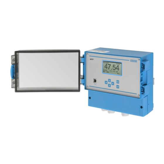
Fig. 2-1 Overview Use in accordance with the requirements The measurement device type NIVUS Full Pipe (NFP) including the active pipe sensor is intended to be used for continuous flow measurement of slight to heavy polluted media in permanent full pipes. -
Page 8: Specifications
1/3 x 0/4–20 mA, load 500 Ohm, 12 bit resolution, accuracy better than 0.1 % (after calibration) 2 switchable relays, loadable up to 230 V AC / 2 A (cos. ϕ 0.9 ) page 8 NFP - Rev. 02 as of 24.11.2009... -
Page 9: General Notes On Safety And Danger
All operations which go beyond steps to install, to connect or to program the de- vice shall be carried out by NIVUS staff or authorised persons or companies only due to reasons of safety and guarantee. 4.1.2 Special Danger Notes Please note that due to the operation in the waste water field, transmitter, sensors and cables may be loaded with dangerous disease germs. -
Page 10: Device Identification
It is important for enquiries and replacement part orders to specify article num- ber as well as serial number of the respective transmitter or sensor. This en- sures correct and quick processing. Art. Nr. NFP-xx W0 xx E x 18-36V DC Ser. Nr. JJKW NFP yyyyy II (2) G [EEx ib] IIB NR. -
Page 11: Installation Of Spare Parts And Parts Subject To Wear And Tear
Before operating the device the user has to ensure, that the local regulations (e.g. for operation in channels) on installation and initial start-up are taken into account, if this is both carried out by the user. NFP - Rev. 02 as of 24.11.2009 page 11... -
Page 12: Functional Principle
Instruction Manual Functional Principle General The NFP is a permanent measurement system for flow measurement of slightly to heavily polluted media with various consistencies in constantly full filled pipes. The method of flow velocity investigation is based on the ultrasound reflection principle. - Page 13 Echo signal images and evaluation Based on the beam angle, the interval between both transmitted signals and the lag of the signal pattern therefore in each single measurement window the flow velocity can be determined. NFP - Rev. 02 as of 24.11.2009 page 13...
- Page 14 From this velocity multiplied by the circular pipe area we can obtain the flow rate. This rate can either be a free programmable analog signal or an impulse signal as well. page 14 NFP - Rev. 02 as of 24.11.2009...
-
Page 15: Device Versions
® Instruction Manual Device Versions The NFP transmitter as well as the accompanying flow velocity are available in different versions. The transmitters primarily vary in terms of maximum pipe diameter, power sup- ply, Ex-protection as well as the number of analog outputs. -
Page 16: Storing, Delivery And Transport
Please check your delivery according to the delivery note for completeness and intactness immediately after receipt. Any damage in transit must be instantly re- ported to the carrier. An immediate, written report must be sent to NIVUS GmbH Eppingen as well. -
Page 17: Installation
For electric installation the local regulations in the respective countries (e.g. VDE 0100 in Germany) must be referred to. The NFP power supply must be separately protected by a 6 A slow-blow fuse and has to be isolated from other facility parts (separate turn-off, e.g. by using an automatic cut-out with >B<... -
Page 18: Transmitter Installation And Connection
Cleaning of the front foil can be undertaken with spirit or if necessary with car polish. If this is not successful, a new front door can be ordered from NIVUS GmbH or your local representative. -
Page 19: Enclosure Dimensions
To be able to use cable diameters outside of the tolerance, glands must be used which ensure IP 65 minimum protection. Unused lead-ins have to be locked with an appropriate dummy plug before the initial start-up. NFP - Rev. 02 as of 24.11.2009 page 19... - Page 20 Instruction Manual Each time before opening the terminal clamp housing (see Fig. 2-1) please ensure to disconnect the NFP from any voltage. It is not allowed to remove the front panel. Before the first connection it is necessary to have a slight pressure on the screw of the clamping connection to ensure its safe opening and a correct connection.
- Page 21 ® Instruction Manual Fig. 6-3 Clamp wiring NFP field enclosure NFP - Rev. 02 as of 24.11.2009 page 21...
-
Page 22: Sensor Connection
For use of the sensors in the Ex-area, the sensor cables must not be directed past the mechanical shield between the termination blocks. Use only the 3 cable connections of the sensor connection block! Page 22 NFP - Rev. 02 as of 24.11.2009... -
Page 23: Nfp Power Supply
Instruction Manual NFP Power Supply Depending on the type of NFP used, it can be supplied with 100-240 V AC. Also possible is a 24 V DC supply (see chapter 4.2). The two slide switches located above the terminals serve as additional power switch. -
Page 24: Overvoltage Protection Precautions
Fig. 6-7 DC model power supply Overvoltage Protection Precautions For effective protection of the NFP transmitter it is necessary to protect power supply and mA-output. NIVUS recommends surge arrestors types EnerPro 220Tr bzw. EnerPro 24Tr (for 24 V DC) for the mains supply, as well type 2x1 24/24 Tr for mA-outputs. - Page 25 ® Instruction Manual Fig. 6-8 Connecting the overvoltage protection for power supply and analog outputs NFP - Rev. 02 as of 24.11.2009 page 25...
-
Page 26: Initial Start-Up
Connecting the overvoltage protection for velocity sensor Initial start-up General Notes to the user Before you connect and operate the NFP you should strictly follow the notes be- low! Please read the instruction manual thoroughly in order to ensure proper function of the measurement system! -
Page 27: Operator Panel
The NFP user surface was designed in a way that even unfamiliar users are able to easily set up basic settings in graphic dialog mode which ensure reliable device operation. -
Page 28: Display
® Instruction Manual Display The NFP has a large back-lit graphic display with a resolution of 128 x 64 pixel. This ensures a comfortable communication mode for the user. Fig. 7-2 Display with main-menus Five basic menus for selection, programming or diagnostics are visible in the headline of the display. -
Page 29: Operation Basics
® Instruction Manual Operation Basics The entire operation of the NFP is menu driven. To navigate within the menu structure use the 4 control keys (see Fig. 7-1). navigates upward in the respective submenu (e.g. PAR/measurement place/name) select preset values e.g. units (m, cm, l/s, m³/s etc.) increase values navigates downward in the respective submenu (e.g. -
Page 30: Parameter Setting
Please observe the bottom line of the display whilst programming, indicating the required measuring unit! This instruction manual describes all programming options of the NFP. Depending on the device type however there might be only one analog output available or the maximum pipe diameter to set might be 450 mm (see Fig. - Page 31 In the basic setting the transmitter operates with a nominal diameter of 250 mm. The NFP will indicate a flow rate if there is a flow velocity prevailing at the mo- ment of initial start-up and the sensor has been installed correctly. This reading of course is not yet relevant to the current application.
-
Page 32: Parameter Storage
Laptop using software tool „PaDa“. This tool is free and can be downloaded from www.nivus.com under >Download/Software<. Connect NFP and PC or Laptop with an USB cable (Type A-B). The „PaDa“ software tool at present can run under Windows® 2000, XP and Vista (32-Bit version). -
Page 33: Pada< Operation
Instruction Manual 9.2.2 >PaDa< Operation After the software has been installed successfully, run the tool under Windows XP either from „Start - All Programs - NIVUS GmbH“ or via the desktop icon (self-installed; German, English or French). Fig. 8-5 PaDa English Select the desired option using the >up<... -
Page 34: Operation Mode (Run)
PIN >2718< and confirmation with ENTER after erasing. Fig. 8-7 Info menu 1 Time of day totalising 2 Day values 3 Current day with cumulated total 4 24 h-day totals 5 Date Fig. 8-8 Day values Page 34 NFP - Rev. 02 as of 24.11.2009... - Page 35 (circular memory function). 1 Error number 2 Number of stored error messages 3 Date of error message 4 Time of error message 5 Type of error / error message Fig. 8-11 Error messages NFP - Rev. 02 as of 24.11.2009 page 35...
-
Page 36: Display Menu (Extra)
/ parameter change as well as mains power failure which might have been oc- curred. Fig. 8-13 System information Fig. 8-14 Additional system information Page 36 NFP - Rev. 02 as of 24.11.2009... - Page 37 The clock set- tings can be modified if required (different time zones, summer time / winter time etc.). First select the menu point “Info”: Fig. 8-16 System time submenu NFP - Rev. 02 as of 24.11.2009 page 37...
-
Page 38: Parameter Menu (Par)
After the new value has been set confirm using the "Enter“ key and type in the code number “2718“ Parameter Menu (PAR) This menu is the most extensive and most important regarding the NFP settings. It nevertheless is sufficient in most cases to set only some essential parameters, which usually are:... -
Page 39: Parameter Menu „Measurement Place
Names may contain up to 15 letters. After the submenu >Name< has been selected the basic setting „NIVUS“ will come up. There is a cursor blinking below the first digit which can be activated by pressing the „up“... - Page 40 It turns out to be helpful to limit the various measurable media according to their damping characteristics of the different measurable media and to determine this selection here. Fig. 8-23 Select medium Page 40 NFP - Rev. 02 as of 24.11.2009...
-
Page 41: Parameter Menu „Flow Velocity
Fig. 8-25 Digital inputs – submenu The NFP comes with one digital input (digital input 1, see connection plan Fig. 6-3) to release the flow velocity measurement or to switch over between opera- tion modes. Both functions are required only in exceptional cases and hence shall be used by the NIVUS commissioning service or authorised persons only. -
Page 42: Parameter Menu "Analog Output
9.5.4 Parameter Menu "Analog Output" Fig. 8-26 Analog output The NFP has 1 or 3 free programmable analog outputs depending on the unit type. Any of the 3 analog outputs can be set and chosen independent of the trans- mitter type. However the outputs are available as hardware only if the respec- tive transmitter type has been ordered and delivered (see Fig. - Page 43 The following functions are available: Hold last value constant 0.0 mA constant 3.6 mA constant 4.0 mA constant 20.457 mA (see also Fig. 8-29) Fig. 8-27 Analog outputs – submenu NFP - Rev. 02 as of 24.11.2009 page 43...
-
Page 44: Parameter Menu „Relays
Limit temperature Relay will energise if a medium temperature limit value [to be set] has been ex- ceeded and will de-energise if the Medium temperature falls below a second limit value). Page 44 NFP - Rev. 02 as of 24.11.2009... - Page 45 Switch point on Defines the “ON” point for the selected limit value. Switch point off Defines the “OFF” point for the selected limit value. NFP - Rev. 02 as of 24.11.2009 page 45...
-
Page 46: Parameter Menu „Settings
It is possible to modify e.g. beam angle or medium sound velocity, transmit voltages or special adjustments regarding the transmit- ter crystal drive. These settings are reserved to be used by the NIVUS initial start-up service as these modifications require comprehensive expert knowledge and do not need to be adjusted during standard use. - Page 47 ® Instruction Manual Fig. 8-35 Execute system reset Entering the PIN-Codes >2718< will cause the NFP to execute a general reset. The unit will be in initialising mode subsequently which requires the operation language to be set. Fig. 8-36 Choose language The NFP will now overwrite the flash memory restarting the program.
-
Page 48: Signal Input/Output Menu (I/O)
Fig. 8-41 Status of relay outputs v-sensor This screen indicates sensor number and software version, measured velocity, investigated Reynolds correction, transmitting frequencies and velocity of sound. This is primarily for service purposes. Page 48 NFP - Rev. 02 as of 24.11.2009... - Page 49 The shape of this distribution may provide information on asymmetric hydraulic conditions, vorticity or similar. Fig. 8-44 Velocity distribution diagram The last screen provides information on amplification, cable noise and various evaluation results between transmitter and sensor. NFP - Rev. 02 as of 24.11.2009 page 49...
- Page 50 Fig. 8-45 System info screen v-Sensor noise This screen helps the NIVUS commissioning service to gain information on possible electric disturbances or interferences between sensor and transmitter. Normally the average value [mean] should be around 0 or slightly higher. The peak value [max] should not exceed 6 –...
-
Page 51: Calibration And Calculation Menu (Cal)
Here it is possible to add a factor to measured and calculated flow velocity val- ues. Normally it is not necessary to use this parameter since the NFP calculation functions have been optimised regarding full pipes and flow velocity detection using the cross correlation method does not require any calibration as long as physical conditions are sufficient. - Page 52 NIVUS herewith in advance refuse responsibility for any possible dam- age to persons or objects at any extent due to the extremely high risk of...
-
Page 53: Parameter Tree
3 Calculated simulated flow value 4 Programmed relay activated by simulation Fig. 8-54 Simulation mode 10 Parameter Tree 10.1 Parameter Menu RUN graphic day values info cycle erase counter error messages NFP - Rev. 02 as of 24.11.2009 page 53... -
Page 54: Parameter Menu Par
0,01 istall. direction positive angle α° digital inputs function inactive gisable v-measurement measurement control logic inverse: NO inverse: YES name analog outputs function inactive flow rate velocity temperature constant current Page 54 NFP - Rev. 02 as of 24.11.2009... - Page 55 "impulse" impulse duration amount setup parameter damping Mai 20 service mode Serv-Code load factory setup NFP - Rev. 02 as of 24.11.2009 page 55...
-
Page 56: Parameter Menu I/O
10.4 Parameter Menu CAL velocity min velocity -1,0000 max velocity 4,0000 v-correction 1,0000 switch point (M/H) 0,9 m/s analog outputs match simulation digital outputs simulation Page 56 NFP - Rev. 02 as of 24.11.2009... -
Page 57: Parameter Menu Extra
UK-english US-english units flow rate veloc. total display format veloc. total language Deutsch english Français display contrast system time info set date set time set format set total-counter NFP - Rev. 02 as of 24.11.2009 page 57... -
Page 58: Troubleshooting
Increase damping. Sensor Check sensor position (towards flow direction, hori- zontal installation) and correct installation depth. Check sensor for sedimentation or obstructions. Page 58 NFP - Rev. 02 as of 24.11.2009... - Page 59 Check input range (0 or 4-20 mA) of following sys- tem. Check input span of following system. Check possible offset of following system. NFP - Rev. 02 as of 24.11.2009 page 59...
-
Page 60: Lists Of Resistiveness
Due to infinitely possible combinations these catalytic effects cannot be verified entirely. If in doubt please contact your NIVUS representative and request a free material sample for long time testing purposes. -
Page 61: Table Of Resistiveness
1-5 % Carbon disulphide 100 % Sulphuric acid 40 % Ethyl alcohol 100 % Carbon tetrachloride (TETRA) 100 % 1/1 1/1L Trichloroethylene (TRI) 100 % 1/1 1/1L Citric acid 10 % NFP - Rev. 02 as of 24.11.2009 page 61... -
Page 62: Resistiveness Legend
Material Names high-density Polyethylene Tetrafluorethylene-Perfluorpropylene (Teflon® FEP) stainless steel 1.4401 (AISI 316) PVDF Polyvinyldifluoride Polyurethane PEEK Polyetheretherketone PPO GF30 Polyphenyloxylene with 30 % glass fibre Page 62 NFP - Rev. 02 as of 24.11.2009... -
Page 63: Maintenance And Cleaning
The device Type NFP incl. accompanying flow velocity sensor is designed to be virtually maintenance-free and free of material wear and does not need to be calibrated. -
Page 64: Emergency
Fig. 4-3 Echo signal images and evaluation....................13 Fig. 4-4 Investigated flow profile ........................14 Fig. 4-5 Type key for NFP measurement transmitter ..................15 Fig. 6-1 Wall Mount Enclosure ........................19 Fig. 6-2 Connection Enclosure ........................20 Fig. 6-3 Clamp wiring NFP field enclosure ..................... -
Page 65: Index
Digital Inputs Cable Glands Display Calibration Menu Display Menu Cleaning Documentation Comparative Measurements Connections Contrast Error diagnosis Copyright Error messages Cross Correlation Method Functional Principle Danger by electric voltage Danger Notes NFP - Rev. 02 as of 24.11.2009 page 65... - Page 66 Operation-Basics Transport Operator Panel Troubleshooting Overvoltage Protection Turn-off procedure Type key 17, 60 Parameter Menu Parameter Setting Units Parameter Tree Use in accordance Parts subject to wear and tear Warnings Qmin Page 66 NFP - Rev. 02 as of 24.11.2009...
-
Page 67: Declaration Of Conformity
Internet: www.nivus.de Für das folgend bezeichnete Erzeugnis: For the following product: Le produit désigné ci-dessous: Bezeichnung: “Ex“ Durchflussmessumformer stationär OCM F / OCM FR / NFP Description: “Ex” permanent flow measurement transmitter Désignation: “Ex”convertisseur de mesure de débit fixe Typ / Type: OCF-00xxxxE…... - Page 68 Désignation: Typ / Type: OCF-00… / OCF-R0... / NFP-… erklären wir in alleiniger Verantwortung, dass die auf dem Unionsmarkt ab dem Zeitpunkt der Unterzeichnung bereitgestellten Geräte die folgenden einschlägigen Harmonisierungsvorschriften der Union erfüllen: we declare under our sole responsibility that the equipment made available on the Union market as of the date of signature of this document meets the standards of the following applicable Union harmonisation legislation: nous déclarons, sous notre seule responsabilité, à...
Need help?
Do you have a question about the NFP and is the answer not in the manual?
Questions and answers