Table of Contents
Advertisement
Quick Links
Instruction manual
NivuSonic Clamp on
Instruction Manual for Measurement System
NivuSonic Clamp On incl. accompanying Sensors
NIVUS GmbH
Im Taele 2
75031 Eppingen, Germany
Phone +49 (0)72 62 - 91 91 - 0
Fax +49 (0)72 62 - 91 91 - 999
E-mail: info@nivus.com
Internet: www.nivus.de
NivuSonic CO - Rev. 00 as of 08.12.2010
(Original Instruction Manual – German)
Valid as of Firmware V2.00
®
Page 1
Advertisement
Table of Contents

Related Manuals for Nivus NivuSonic Clamp On


Summary of Contents for Nivus NivuSonic Clamp On
- Page 1 ® Instruction manual NivuSonic Clamp on Instruction Manual for Measurement System NivuSonic Clamp On incl. accompanying Sensors (Original Instruction Manual – German) Valid as of Firmware V2.00 NIVUS GmbH Im Taele 2 75031 Eppingen, Germany Phone +49 (0)72 62 - 91 91 - 0 Fax +49 (0)72 62 - 91 91 - 999 E-mail: info@nivus.com...
- Page 2 A - 2201 Gerasdorf bei Wien Tel.: +43 (0)2246 32319 Fax: +43 (0)2246 32386 E-Mail: austria@nivus.com Internet: www.nivus.de NIVUS Sp. z o. o Ul. Hutnicza 3 / B-18 81-212 Gdynia, Poland Phone +48 (0)58 / 760 20 15 Fax +48 (0)58 / 760 20 14 E-mail: biuro@nivus.pl...
- Page 3 ® Instruction manual NivuSonic Clamp on Translation If the device is sold to a country in the European Economic Area (EEA) this instruction handbook must be translated into the language of the country in which the device is to be used.
-
Page 4: Table Of Contents
® Instruction manual NivuSonic Clamp on Contents Table of Contents Contents ................4 Table of Contents ................4 Overview and use in accordance with the requirements .6 Overview ..................6 Use in accordance with the requirements ........7 Specifications ................8 2.3.1 Transmitter ..................8 2.3.2 Clamp On System .................8... - Page 5 Instruction manual ® NivuSonic Clamp on 6.6.3 Communication Setup and Connection via Access Portal..35 6.6.4 Data Transmission ..............37 Initial start-up ..............42 General..................42 Operator Panel ................43 Display..................44 Operation Basics .................46 Parameter Setting ..............47 Quick Guide Parameter Setting (Quick Start ) ......47 Parameter Setting Basics............48...
-
Page 6: Overview And Use In Accordance With The Requirements
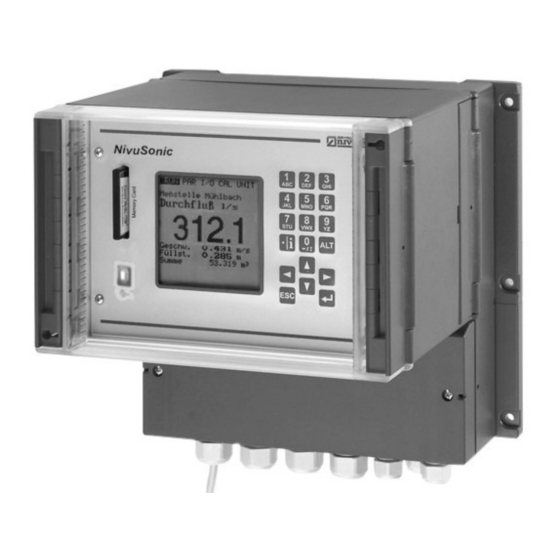
® Instruction manual NivuSonic Clamp on Overview and use in accordance with the requirements Overview Slot with plugged memory card Graphic display Keypad Cable glands Terminal clamp housing USB Port Clamp on sensors (pair) Fig. 2-1 Overview Page 6... -
Page 7: Use In Accordance With The Requirements
2.3 must be strictly kept. All cases which vary from these conditions and are not passed by NIVUS GmbH in writing are left at owner’s risk. The device is exclusively intended to be used for purposes as described above. -
Page 8: Specifications
® Instruction manual NivuSonic Clamp on Specifications 2.3.1 Transmitter Power supply 100 to 240 V AC, +10 % / -15 %, 47 to 63 Hz or 24 V DC ±15 %, 5 % residual fluctuation Power consumption max. 48 VA... -
Page 9: Accessories (Optional)
® Instruction manual NivuSonic Clamp on 2.3.3 Accessories (optional) Memory card Type: Compact Flash Card; storage capacity: 128 MB; fabricator: SanDisk Readout adapter Adapter unit for PCMCIA interface, primarily for data readout via Laptop or Notebook Readout unit With USB interface for connecting to PC. -
Page 10: General Notes On Safety And Danger
All operations, which go beyond steps to install, to connect or to program the device, must be carried out by NIVUS staff only due to reasons of safety and guarantee. 3.1.2 Special Danger Notes Please note that due to the operation in the waste water field, transmitter, sensors and cables may be loaded with dangerous disease germs. -
Page 11: Device Identification
® Instruction manual NivuSonic Clamp on Device Identification The instructions in this manual are valid only for the type of device indicated on the title page. The nameplate is fixed on the bottom of the device and contains the following. -
Page 12: Installation Of Spare Parts And Parts Subject To Wear And Tear
® Instruction manual NivuSonic Clamp on Installation of Spare Parts and Parts subject to wear and tear We herewith particularly emphasize that replacement parts or accessories, which are not supplied by us, are not certified by us, too. Hence, the installation and/or the use of such products may possibly be detrimental to the device’s abil-... -
Page 13: Functional Principle
® Instruction manual NivuSonic Clamp on Functional Principle General NivuSonic CO is a non-contact, stationary measurement system for flow meas- urement and hence is pressure-independent. The storage of detected readings and remote access using TCP/IP is carried out via network connection, Intranet or Internet. -
Page 14: Flow Velocity Detection
® Instruction manual NivuSonic Clamp on Flow velocity detection The flow velocity is determined by using the ultrasonic transit time principle. 1 Sensor 1 2 Sensor 2 Fig. 4-2 One-path transit time measurement principle This measurement principle is based on directly measuring the transit time of acoustic signals between two ultrasonic sensors, the so-called hydro-acoustic converters. - Page 15 ® Instruction manual NivuSonic Clamp on Fig. 4-3 Two-path transit time measurement principle Investigate the velocity as described below presuming C>>υ − υ ⋅ − − ⋅ Φ α − − −...
-
Page 16: Flow Calculation
® Instruction manual NivuSonic Clamp on Flow calculation In case of using single-path or two-path installations in one level under the con- dition υ ⋅ Given: average flow velocity υ cross-sectional flow area it is required to involve a velocity coefficient k in order to compensate the differ- υ... -
Page 17: Storing, Delivery And Transport
Please check your delivery according to the delivery note for completeness and intactness immediately after receipt. Any damage in transit must be instantly re- ported to the carrier. An immediate, written report must be sent to NIVUS GmbH Eppingen as well. -
Page 18: Storing
Transportation must be carried out in the original packaging. Return The units must be returned at customer cost to NIVUS Eppingen in the original packaging. Otherwise the return cannot be accepted! -
Page 19: Installation
6.2.1 General The transmitter mounting place has to be selected according to certain criteria. Please strictly avoid: direct sunlight (use weatherproof cover if necessary, e.g. NIVUS weather- proof cover Art. No. ZMS0 180000) heat emitting objects (max. ambient temperature: +50 °C) objects with strong electromagnetic fields (e.g. -
Page 20: Enclosure Dimensions
Cleaning of the front foil can be undertaken with spirit or if necessary with car polish. If this is not successful, a new front door can be ordered from NIVUS GmbH or your local representative Never change the cable lengths of the sensors delivered since this will lead to faulty measurements or even complete measurement failures. -
Page 21: Transmitter Connection
Due to reasons of better handling the flow velocity sensors are connected using plug connections. The pre-configured NIVUS sensor cable ends or single- as well as multi wired cables with cross-sectional dimensions of 0.18-2.5 mm² can be connected to these plug connections. - Page 22 ® Instruction manual NivuSonic Clamp on Fig. 6-2 Clamp wiring NivuSonic CO wall mount enclosure Page 22...
-
Page 23: Sensor Installation And Connection
® Instruction manual NivuSonic Clamp on Sensor Installation and connection 6.3.1 Sensor installation The inserted sensors have to be fastened hard and tight. Use only non-corrosive fastening material! Before installing the sensor, please check material and wall thickness of the pipe. The material should be cast steel, steel or stainless steel. - Page 24 ® Instruction manual NivuSonic Clamp on 1 Sensor 1 2 Sensor 2 Fig. 6-5 1 path measuring, path arrangement: v echo 1 Sensor 1 2 Sensor 2 Fig. 6-6 1 path measuring, path arrangement: diagonal To avoid disturbances from electrical interferences, the sensor cable must not be laid close or parallel to engine (motor) lines or main power lines.
-
Page 25: Choosing Sensor Position And Required Distances
In case of horizontally laid pipes avoid pipe top and pipe bottom as mounting place (risk of soiling or air bubbles resulting in measurement failure). NIVUS recommends a mounting position of -45° ... +45° to the horizontal.. X = Recommended sensor installation positions... - Page 26 ® Instruction manual NivuSonic Clamp on α ≤ 15° L ≥ min. 3x DN L ≥ min. 5x DN α ≤ 45° L ≥ min. 5x DN L ≥ min. 10x DN α ≤ 90° L ≥ min. 10x DN L ≥ min. 15-20x DN Fig.
- Page 27 Instruction manual ® NivuSonic Clamp on A correct and reliable measurement can be performed only in full filled pipes. For this reason do not install measurements in downpipes or at the highest point of the pipeline. 1 = recommended range in almost horizontal position...
-
Page 28: Sensor Connection
NivuChannel transmitter (one or two sensor pairs). Use only the dedicated cable provided by NIVUS for connection and / or extension purposes. The sensor cable can be ordered from NIVUS using the respective article no. (see ). It is not allowed to use common extensions in case of different applications or to use a common signal cable to extend separate level and flow velocity measurements. -
Page 29: Nivusonic Co Power Supply
Instruction manual ® NivuSonic Clamp on Fig. 6-14 Connection of sensor 2 to the NivuSonic CO Improper connections which lead to higher transition resistance or the use of other cables may lead to disturbance and errors in the measurement. NivuSonic CO Power Supply Depending on the type of NivuSonic CO k used, it can be supplied with 85- 260 V AC. - Page 30 ® Instruction manual NivuSonic Clamp on Fig. 6-16 AC model power supply Fig. 6-17 DC model power supply Page 30...
-
Page 31: Overvoltage Protection Precautions
For effective protection of the NivuSonic CO it is necessary to protect power supply; mA-outputs and inputs NIVUS recommends surge arrestors types EnerPro 220Tr or EnerPro 24Tr (for 24V DC) for the mains supply, as well type DataPro 2x1 24/24 Tr for mA-outputs and inputs. -
Page 32: Communication
There is no need to install any additional software if there is the latest Internet browser and the latest Java plug-in available on your network PC/Laptop. If you wish to access the unit via the NIVUS Internet portal it is necessary to have a permanent Internet connection established (modem or DSL). Once hav-... - Page 33 Instruction manual ® NivuSonic Clamp on Operator operational conditions, progress lines, sensor status etc. can be selected and viewed saved data and parameter files can be downloaded device settings can be modified permanently data files can be deleted memory card can be formatted...
-
Page 34: Communication Options
® Instruction manual NivuSonic Clamp on 6.6.2 Communication Options The following different options are available for communication with the NivuSo- nic CO: Direct Ethernet connection between PC/Laptop and NivuSonic CO using a cross-link cable. Ethernet level connection via TCP/IP, network connection via Ethernet hub or switch. -
Page 35: Communication Setup And Connection Via Access Portal
6.6.3 Communication Setup and Connection via Access Portal Setting up an Internet communication for one or several NIVUS flow meas- urement units requires an initial setup by NIVUS or a company which is authorised by NIVUS Setting up a modem connection (analog, ISDN,GPRS or similar) will cause communication expenses depending on the connection chosen. - Page 36 „User Name“ and „Password“. You are going to receive both codes after the initial setup has been carried out by NIVUS. We highly recommend to change the password during the first log-in. Fig. 6-22 Start of communication...
-
Page 37: Data Transmission
PC! © The Java Applet is a third party software and NIVUS therefore cannot accept any liability of the use of it. Download and installation of programs or software may damage your com- puter and is therefore completely left at user’s risk! NivuSonic CO - Rev. - Page 38 ® Instruction manual NivuSonic Clamp on ® Fig. 6-26 Java Applet starting ® After starting JAVA successfully, the NivuSonic CO display now is indicated in the same manner as if being on-site. The NivuSonic CO can now be operated by using the PC keyboard (arrow keys >left<, >right<, >up<, >down<...
- Page 39 ® Instruction manual NivuSonic Clamp on The file size will be reduced by approx. 75 % by using the .gz-format and hence is recommended particularly if large measurement place files have to be trans- mitted via analog modem and GPRS (reduces expenses).
- Page 40 ® Instruction manual NivuSonic Clamp on Fig. 6-30 Created backup folder Files which have been moved into the backup folder will be deleted irrevocably and permanently from the memory card if clicked again for deleting. Fig. 6-31 Contents of created backup folder Fig.
- Page 41 Log out the on-site unit by using the >Logout< button located on the left-hand side of the screen as well. This will take you back to the NIVUS homepage. If no data transmission has been executed for 5 minutes, the Nivu- Sonic CO will automatically interrupt the connection in order to avoid unnec- essary expenses.
-
Page 42: Initial Start-Up
® Instruction manual NivuSonic Clamp on Initial start-up General Notes to the user Before you connect and operate the NivuSonic CO ayou should strictly follow the notes below! This instruction manual contains all necessary information to program and to operate the device, addressing qualified technical staffs that have appropriate knowledge about measurement technology, automation technology, information technology and waste water hydraulics. -
Page 43: Operator Panel
Instruction manual ® NivuSonic Clamp on Operator Panel There is a comfortable 18-button keypad available to input required data. 1 Comma / info 2 Figure – letter block 3 Shift key 4 0 / - navigation button 5 Control 6 Enter 7 Escape Fig. -
Page 44: Display
® Instruction manual NivuSonic Clamp on Display The NivuSonic CO has a large back-lit graphic display with a resolution of 128 x 128 pixel. This ensures a comfortable communication mode for the user. 1 Total 2 Velocity 3 Flow measurement... - Page 45 Instruction manual ® NivuSonic Clamp on Five basic menus can be selected, visible in the headline of the display. They can be selected individually. The menus are: Standard operation mode. Apart from indicating the names of meas- urement places it allows to display time, flow volume, flow level and...
-
Page 46: Operation Basics
® Instruction manual NivuSonic Clamp on Operation Basics The entire operation is menu driven and supported by explanatory graphics. To navigate within the menu structure use the 4 control keys (see chapter 7.2). Use these buttons to select main menus. -
Page 47: Parameter Setting
Instruction manual ® NivuSonic Clamp on Parameter Setting Quick Guide Parameter Setting (Quick Start ) In case of standard applications – part filled standard channel; level and flow ve- locity measurement by one pair of sensors; 1x mA output for flow rate; 1x im-... -
Page 48: Parameter Setting Basics
® Instruction manual NivuSonic Clamp on Parameter Setting Basics The transmitter in the background operates with the settings which have been entered at the beginning of the parameter setting. Just after you finish the new entries, the system asks to accept the new values. - Page 49 Instruction manual ® NivuSonic Clamp on The initial start-up dialog is the language selection: Fig. 8-2 Language Selection Select the desired language by using the arrow keys and press >Enter< to con- firm. Please press key once The transmitter begins communication evaluating the flow velocity and coordi- nates both processor programs.
-
Page 50: Operation Mode (Run)
® Instruction manual NivuSonic Clamp on Operation Mode (RUN) This menu is a display menu for standard operation mode. Containing the follow- ing sub menus, it is not required for parameter setting: Fig. 8-3 Operation mode selection Display (basic screen) with information about the name of measurement place, Normal time, medium temperature, flow quantity, average velocity and total volume. -
Page 51: Display Menu (Extra)
Instruction manual ® NivuSonic Clamp on The internal memory has a capacity of 90 days. Subsequently, saved data will be overwritten erasing the oldest data sets first. Indicated measurement values will be scaled automatically during scrolling and therefore might change in order to ensure the best reading available. - Page 52 ® Instruction manual NivuSonic Clamp on Fig. 8-8 Selection of individual units This menu contains the following sub menus: Units Flow Velocity Total For each of these 3 measured values you can select a unit which appears on the display. Depending on the unit system selected, there are various units available.
- Page 53 Instruction manual ® NivuSonic Clamp on The complete system time is indicated after the settings have been confirmed: 1 Date 2 Week number 3 Time Fig. 8-10 Complete system time This menu point is for indicating purposes only. Hence the system time cannot be adjusted here.
-
Page 54: Parameter Menu (Par)
® Instruction manual NivuSonic Clamp on Parameter Menu (PAR) Fig. 8-13 Selecting the measurement place This menu is the most extensive and most important regarding the NivuSonic CO settings. It nevertheless is sufficient in most cases to set only some essential... -
Page 55: Parameter Menu „ Measurement Place
Names may contain up to 21 letters. Setting ment place) the name is quite similar to operating a mobile phone: After the submenu >Name< has been selected the basic setting “nivus“ will come up. Toggle between uppercase and lowercase letters by using the >up< or >down< keys. - Page 56 ® Instruction manual NivuSonic Clamp on Description of Keys: Moves the cursor to the left-hand or the right-hand side. Moving the cursor to the left-hand side will delete the character left of the cursor. Moving the cursor to the right-hand side creates a space char- acter.
- Page 57 Instruction manual ® NivuSonic Clamp on Rectangle: Fig. 8-18 Channel dimensions for Rectangle Enter the dimensions of rectangular channels here. The sludge level set is going to be calculated as non-moving channel sub-area Sludge level with horizontal surface and will be subtracted from the wetted total hydraulic area prior to performing flow calculation.
-
Page 58: Parameter Menu „Ldv
® Instruction manual NivuSonic Clamp on 8.5.2 Parameter Menu „LDV“ The parameter settings made here are extremely important regarding the ge- ometry of the measurement paths. Number as well as positions of single paths (up to 2) can be set here. These settings determine the functionality of the entire measurement. - Page 59 Instruction manual ® NivuSonic Clamp on Fig. 8-23 Path configuration "v-echo" or "diagonal" K-Factor Fig. 8-24 K-factor entry Thanks to the K-factor it is possible to adjust and to correct the average velocity within the measurement path by utilising an externally measured velocity. Nor- mally the factor shall be set to 1 however.
-
Page 60: Parameter Menu "Analog Inputs
® Instruction manual NivuSonic Clamp on Fig. 8-26 Pipe parameters 8.5.3 Parameter Menu "Analog Inputs" This menu allows to use up to 4 analog inputs for the recording of external sig- nals. The signals are not going to processed in any way but can be merely saved to be available for communication purposes (ModBus or similar, 0- 100 %). - Page 61 Instruction manual ® NivuSonic Clamp on Select from analog outputs 1–4 which one is to be set by using the following Channel number parameters. No entry required. Setting a name here is helpful only if the analog output is to Name be saved on memory card.
-
Page 62: Parameter Menu „Digital Outputs
® Instruction manual NivuSonic Clamp on This means that flow = 0 is going to output a mA signal in the middle of the measurement span. Example: 4 mA = -100 l/s 20 mA = 100 l/s In this case the signal output is 12 mA if flow = 0. Backwater will cause the ana- log signal to decrease, positive flow will cause the signal to increase. - Page 63 Instruction manual ® NivuSonic Clamp on Functions are going to be assigned to the relay which has been chosen by en- Function tering the >Channel Number<. Available are: inactive (relay will energise if a flow limit value [to be set] has been exceeded and...
- Page 64 ® Instruction manual NivuSonic Clamp on Fig. 8-33 Setting the trigger levels Depending on the settings (start point higher than stop point or vice versa), the according switching behaviour can be considered as switching threshold (ON>OFF) or as in-bounds alarm (ON<OFF).
-
Page 65: Parameter Menu "Setup Parameter
Instruction manual ® NivuSonic Clamp on Select from the options below: On-time (select an impulse duration between 0.01 and 2.0 seconds. The ra- tio between impulse and break is 1:1. It is useful to increase the impulse du- ration beyond the 0.5 sec. default setting if slow PLC inputs or mechanic counters are in use). -
Page 66: Parameter Menu "Storage Mode
Fig. 8-37 Storage mode - submenu Before enabling this menu plug in a NIVUS compact flash card with a capacity of 16 ..128 MB. This card is available from your NIVUS representative if required. Use memory cards purchased from NIVUS only. Other manufacturer’s cards may lead to irreversible loss of data or measurement failure (e.g. - Page 67 3000 - 4000 Byte has been cumulated data will be saved on card as well). The data will be saved in a special NIVUS format. The name is „Name of meas- urement place set“.TXT<. This file can be read and processed either using Excel spreadsheet application or by using >NivuDat32<...
- Page 68 ® Instruction manual NivuSonic Clamp on Operation mode Fig. 8-40 Activating operation mode Mode Pressing this key toggles between: = no data saving periodic = cyclic storage of fill level, flow velocity and volume Periodic interval This parameter is to set the memory cycle. Select from settings between 1 min- ute and 1 hour.
- Page 69 ® Instruction manual NivuSonic Clamp on = system parameters will be saved (system errors, error mes- sages, system ON and OFF events etc.) Unit system Select between data storage in metric system (e.g. litres, cubic metres, cm/s etc.), English system (ft, in, gal/s, etc.) or American system (fps, mgd etc.).
-
Page 70: Data Structure On Memory Card
The file PARAMET.NIV is required in order to upload data to NivuSonic CO. PARAMET.TXT is the print version of PARAMET.NIV as text file. Use memory cards purchased from NIVUS only. Other manufacturer’s cards may lead to irreversible loss of data or measurement failure (e.g. permanent transmitter reset). -
Page 71: Parameter Menu "Communication
NIVUS service. Due to this reason please complete the form which can be found in an- nex 11 and return it to NIVUS in order to prepare initialisation. Please fill out the form as complete as possible. - Page 72 ® Instruction manual NivuSonic Clamp on Fig. 8-48 Remote access By selecting this point it is possible to define if the IP address (required for unit Ethernet access) is to be assigned automatically or manually. If >YES< the assignment will be executed by DHCP routine (similar to Internet PC setting „Get IP address automatically“).
- Page 73 Instruction manual ® NivuSonic Clamp on If connection type >Modem< or >Mod Eth.< has been selected enter the type Modem of integrated modem here. The built-in modem can be specified from the device ID which can be found on the unit (see also Chapter 4.4).
- Page 74 ® Instruction manual NivuSonic Clamp on Fig. 8-53 ISDN modem parameter settings ISDN modem: Provider dial-up: see analog modem User name: see analog modem Password: see analog modem MSN: Multiple Subscriber Number – the ISDN number assigned to the user by the telecommunication provider (normally there are 3 numbers min.
- Page 75 Data format: Select between text file and binary file. Binary files are for inte- gration of the unit into the "NICOS" process conducting system by NIVUS. Cycle: This defines the cycle to send the data mails (e.g. every 24 hours) Delay: The delay entered here refers to the transmission cycle set.
- Page 76 ® Instruction manual NivuSonic Clamp on Required only if a direct 1:1 connection to the NivuChannel is desired to be set Direct Access up via Laptop/PC, network cable and the internal RJ45 interface. In this case determine both; password as well as user name for this internal connection on PC/Laptop.
-
Page 77: Signal Input/Output Menu (I/O)
Instruction manual ® NivuSonic Clamp on Signal Input/Output Menu (I/O) This menu includes several submenus which both serve to assess and to check sensors as well as to control signal inputs and outputs. It allows to indicate vari- ous values (current values of inputs and outputs, relay conditions, echo profiles, individual velocities etc.), however does not enable to influence signals or condi-... -
Page 78: I/O Menu „Digital Outputs
® Instruction manual NivuSonic Clamp on 8.6.2 I/O Menu „Digital outputs” This submenu indicates the calculated conditions to be output on the relay. We distinguish between logically "OFF“ or "ON“. Fig. 8-61 Screen digital values The actual currents fed to the digital output clamps will not be indicated. The only signal visible is the signal the analog output converter receives for output. -
Page 79: I/O Menu "Interfaces
Instruction manual ® NivuSonic Clamp on Fig. 8-64 Velocity screen Missing velocities indicate that e.g. there is no more water in the measurement path which interrupts signal transmission between the sensors. Please also check additionally if the sensors have been connected correctly. - Page 80 ® Instruction manual NivuSonic Clamp on Fig. 8-67 Card information Information can be recalled only if the memory card is plugged. To be able to in- dicate the remaining capacity time the card has to be plugged one hour at least The card can be replaced at any time unless the display indicates >Memory...
-
Page 81: I/O Menu Communication
Instruction manual ® NivuSonic Clamp on The progress is going to be indicated by a corresponding bar: Fig. 8-69 Saving parameters on memory card The menu point „Load parameters“ first of all shows all programming files avail- able on the card. The file is going to be transmitted to the NivuSonic CO after the point has been selected. -
Page 82: Calibration And Calculation Menu (Cal)
Simulations are allowed to be executed exclusively by NIVUS expert personnel or by expert companies trained by NIVUS in cooperation with experienced us- ers. NIVUS herewith refuse in advance to be responsible for any possible... - Page 83 Instruction manual ® NivuSonic Clamp on Fig. 8-73 Selecting the analog output simulation Choose the analog output which is to be simulated by entering the respective Channel number number from 1 – 4 or by using the >left< or >right< arrow keys in the simulation main menu.
- Page 84 ® Instruction manual NivuSonic Clamp on This function allows to simulate a theoretical flow by entering supposed level Simulation and velocity values without having these values actually available. The Ni- vuChannel is going to calculate the current flow value by using the simulated values based on the channel dimensions set.
-
Page 85: Parameter Tree
Instruction manual ® NivuSonic Clamp on Parameter Tree Operation Mode (RUN) standard day values info interval erase memory? errors trend flow rate velocity Parameter menu (PAR) part 1 measurement place name nivus channel shape(s) round pipe radius pipe rectangle channel geometry... - Page 86 ® Instruction manual NivuSonic Clamp on Parameter menu (PAR) part 2 analog inputs channel number name dac_1 function inactive archived value measurement range 0-20mA 4-20mA 0-10V 0-5V unit 0/4mA: 0.0 20mA: 20.0 linearisation fix points offset analog outputs channel number...
- Page 87 Instruction manual ® NivuSonic Clamp on Parameter menu (PAR) part 3 setup parameter load factory setup load factory setup code no. damping constancy storage mode -> if "periodic" is selected cycle interval inactive periodic 1-60 Min select data system unit...
- Page 88 ® Instruction manual NivuSonic Clamp on Parameter menu (PAR) part 4 communication remote access modem inactive port active Ethernet Modem with remote access only modem active provider 01920782 user name arcor password internet email email inactive aktive mail sercer from...
- Page 89 Instruction manual ® NivuSonic Clamp on Signal Input/Output Menu (I/O) analog inputs values in [mA/V] calc. Values analog outputs digital outputs sensors t-sensor(s) LDV_sensor LDV signal strength interfaces memory card info format card store parameter restore paramenter store backup communication Modbus Read Input Reg.
- Page 90 ® Instruction manual NivuSonic Clamp on Display Menu (EXTRA) Extra units unit system metric UK-english US-english flow rate velocity total m³ language Deutsch English Français Czech Italiano Español Polski Dansk display contrast backlight (*)load CPU32-progr. (*)load DSP-progr. set time info...
-
Page 91: Troubleshooting
Call up error memory. J Depending on error mes- sages take the respective measures (check cables, plug and socket connections, sensor installation). f >CPU Error< is indicated consult NIVUS service personnel. Investigate the moment of failure in menu RUN –... - Page 92 ® Instruction manual NivuSonic Clamp on Unstable measure- Disadvantageous hydraulic Verify the quality of the measurement place by utilis- ment values conditions on measure- ing the graphic flow velocity profile indication. ment place Relocate sensors to a place with better hydraulic conditions (extend calming section).
- Page 93 Memory card with more than 128 MB capacity can- not be used currently! Memory card formatted on PC. Send card to NIVUS. Memory card not firmly plugged (not deep enough). Memory card not plugged for a sufficient period of time (min.
-
Page 94: Internet Connection Questionnaire
ISDN modem as well as DSL or GPRS modem. Prior to entitling NIVUS to set up the connection it is required to specify several technical details. If you wish to set up several units please fill out one question- naire per unit. - Page 95 Instruction manual ® NivuSonic Clamp on *Mandatory specifications. Request from user system administrator if required. Requesting Company: *Contact Person: *Phone: *Street: Fax: *Postal Code, City: E-mail: Transmitter Art. No.: Transmitter Serial No.: Location : (if not as stated above) Postal Code, City:...
- Page 96 ................Dial-up: ................User name: ................Password: ................Internet by call – to be set up by NIVUS upon request * Gate Access * Java Run Time Environment previously set up by NIVUS available not yet set up not available desired main user name: (suggested: company.admin)
-
Page 97: Maintenance And Cleaning
If required clean the transmitter enclosure if with a dry, lint-free cloth. For heavy pollution NIVUS recommends the use of surface-active agents. The use of abrasive cleansing agents is not allowed. -
Page 98: Table Of Pictures
® Instruction manual NivuSonic Clamp on 15 Table of Pictures Fig. 2-1 Overview .............................6 Fig. 3-1 NivuSonic CO nameplate........................11 Fig. 3-2 Nameplate for Clamp on sensors, Typ NIC0 ..................11 Fig. 4-1 Assembly of clamp on sensors incl. straps ..................13 Fig. 4-2 One-path transit time measurement principle ...................14... - Page 99 Instruction manual ® NivuSonic Clamp on Fig. 8-18 Channel dimensions for Rectangle ....................57 Fig. 8-19 Selection Q-min..........................57 Fig. 8-20 Selection of LDV Parameters......................58 Fig. 8-21 Path number entry..........................58 Fig. 8-22 Entering active measurement paths and measuring orientation............58 Fig. 8-23 Path configuration "v-echo" or "diagonal" ..................59 Fig.
-
Page 100: Index
® Instruction manual NivuSonic Clamp on 16 Index Functional Principle Analog Inputs Analog Outputs GPRS modem Approach Channel Graphic Display Back-lit Display Analog Outputs Digital Outputs Cable Sensors Bending Radius Initial start-up Cable glands Installation Calibration and Calculation Menu Interfaces... - Page 101 Instruction manual ® NivuSonic Clamp on Specifications Clamp On System Parameter Menu Transmitter Parameter Setting Storage Parameter Tree Storing Parts subject to wear and tear Pulse Parameter Total counter Translation Quick Start Transmitter Connection Receipt Installation Remote Access Transport Return...
-
Page 102: Appendix
® Instruction manual NivuSonic Clamp on 17 Appendix Settings and verification of MODBUS TCP data transmission It is recommended to save the unit parameters prior to activation of the Modbus transmission protocol. The unit parameters must be set anew after a general reset has been carried out. - Page 103 Instruction manual ® NivuSonic Clamp on Submenu Communication => Modbus Submenu Modbus => Measurement Span Submenu Modbus => Port Menu I/O Submenu Communication => modbus Set a fixed IP address as described. It is possible to use a dynamic address. However the master then is forced to recall the protocol (Request) by using the same name.
- Page 104 ® Instruction manual NivuSonic Clamp on The measurement spans of the values Q, h, V and T can be modified under PAR > Communication > Modbus > Measurement span. Important: Modifying the scale at this point results in a different bit resolution within the protocol.
- Page 105 Instruction manual ® NivuSonic Clamp on Status bits to 33-48 50-65: Sensor2 Gate 1-16 (scaled) Status bits to 50-65 67-82: Sensor3 Gate 1-16 (scaled) Status bits to 50-65 84-99: Sensor4 Gate 1-16 (scaled) 100: Status bits to 84-99 101-108 average velocities V1-4 or (path 1-8 (scaled))
- Page 106 ® Instruction manual NivuSonic Clamp on Example (Address 6): Bit0 Status Flow Bit1 Status Level Bit2 Status Velocity Bit3 Status Water temperature Bit4 Status Air temperature Holding Registers Function Code(s): “Read Holding Registers” (0x03) „Write Single Register“ (0x06) „Write Multiple Registers“ (0x10)
- Page 107 Instruction manual ® NivuSonic Clamp on analog outputs Memory1 Memory2 digital inputs digital outputs Totaliser Program memory data storage Operational error sensor1 controller Compact-Flash Card sensor2 sensor3 sensor4 buffer battery Ethernet Modem PC diagnosis GPRS / GSM-Pin 25-32: not connected...
- Page 108 ® Instruction manual NivuSonic Clamp on typedef struct scalar { float min; float max; The data type "float" corresponds to the "IEEE-Single"-Definition, transmission is executed in "big-endian". Array member "min" represents the corresponding value for 0 digits, "max" represents the measurement value at 32767 digits.
-
Page 109: Declaration Of Conformity
18 Declaration of Conformity...
Need help?
Do you have a question about the NivuSonic Clamp On and is the answer not in the manual?
Questions and answers