Sign In
Upload
Manuals
Brands
Nivus Manuals
Transmitter
NivuFlow Mobile 600
User Manuals: Nivus NivuFlow Mobile 600 Flowmeter
Manuals and User Guides for Nivus NivuFlow Mobile 600 Flowmeter. We have
3
Nivus NivuFlow Mobile 600 Flowmeter manuals available for free PDF download: Instruction Manual
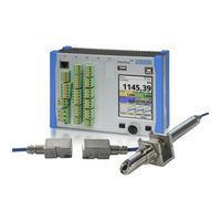
Nivus NivuFlow Mobile 600 Instruction Manual (149 pages)
Flow Measurement Transmitter
Brand:
Nivus
| Category:
Transmitter
| Size: 31.17 MB
Table of Contents
Copyrights and Property Rights
3
Document Modifications
4
Table of Contents
5
General
10
Signs and Definitions Used
10
Abbreviations Used
11
Colour Code for Wires and Single Conductors
11
1 About this Manual
10
Applicable Documentation
10
2 Connections and Operating Elements
11
Power Supply
11
Transmitter
11
Nivuflow Mobile Operating Elements
12
Rechargeable Batteries
12
Interfaces
13
Safety Instructions
14
3 Used Symbols and Signal Words
14
Valuation of the Accident Level
14
4 Safeguards and Precautions
15
Warning Notices on the Product (Option)
15
5 Liability Disclaimer
17
6 Use in Accordance with the Requirements
17
7 Ex Protection
18
8 User's Responsibilities
19
9 Personnel Requirements
19
Delivery, Storage and Transport
20
10 Delivery
20
11 Reception Inspection
20
12 Storage
21
13 Transport
21
14 Return
21
Product Specification
22
15 Product Construction and Overview
22
Connectable Sensors
23
16 Device Identification
23
Enclosure Dimensions
23
17 Specifications
25
18 Configuration/Device Types
26
Functional Description
27
19 Operating Ranges
27
Flow Velocity Detection
27
20 Functional Principle
27
Flow Calculation
29
Installation and Connection
30
21 General Information on Installation
30
Before Installation
30
Gaskets
30
Installation Place
30
PU Stickers on Enclosure Frame
30
Connection Sockets
31
22 Electrical Installation/Power Supply
31
Securing the Instrument
31
Rechargeable Battery Pack
32
Removing/Inserting the Rechargeable Battery Pack
32
Charging the Rechargeable Battery Pack
33
Operation/Charging Via an Alternative Power Supply
35
Operation/Charging with Direct Connection to Mains Power
35
Sensor Installation Basics
36
23 Sensor Installation in General
36
Installation of Clamp-On Sensors
37
Installation of Wet Sensors
38
Cable for Sensor Connection
39
24 Sensor Connection
39
Overvoltage Protection Measures
40
25 Single External Connection for Inputs/Outputs
41
26 Connecting the Connector Box for Inputs/Outputs
42
27 (T-Shape) Antenna for GPRS Data Remote Transmission
44
Putting into Operation
45
28 Notes to Users
45
29 Indication System of Status LED on Nivuflow Mobile
45
Android Operating System
46
General
46
30 Setting up Connection
46
Ios Operating System
49
Windows Operating System
52
Display Overview
55
31 Menu Operation/Overview
55
Saving Parameters
56
Menus
57
Start-Up Examples
58
32 Measurement with Clamp-On Sensors
58
General
58
Programming a 1-Path Diametrically Opposed Measurement
58
Simple Parameter Setting
58
Extended Parameter Setting
61
33 Measurement with Wet Sensors
61
Parameter Setting
62
34 General Programming
62
Change WLAN Password
62
Save Parameters
62
Change Instrument SSID
63
Lost Password
63
Automatic Data Transmission to USB Stick
64
35 Parameter Setting Using Quick Start
65
Functions of the First Menu Level
67
Main Menu
67
Menu - Application
67
36 Parameter Functions
67
Menu - Data
68
Menu - System
69
Menu - Communication
70
Menu - Display
70
Menu - Battery (12V)
71
Menu - Quick Start
71
Menu - Alert
72
Menu Measure Place
73
Name of Measurement Place
73
37 Parameters Menu Application
73
Number of Paths
74
Transit Time Mode
74
Channel Profiles
75
Medium
75
Medium Temperature
75
Wall Material
76
Damping
77
Lining
77
Low-Flow Suppression
77
Sludge Level
77
Menu V-Paths
78
Sensor Types in >Clamp-On< Transit Time Mode
78
Stability
78
Sensor Mounting Position
79
Sensor Types in >Wet< Transit Time Mode
79
Analog Inputs
80
Menu Inputs/Outputs (Analog and Digital)
80
V-Minimum and V-Maximum
80
Analog Outputs
81
Digital Inputs
83
Digital Outputs
84
Diagnostics Menu
85
38 Parameter Menu Data
85
Trend
86
Day Totals
87
Data Memory
89
Information
91
39 Parameter Menu System
91
Region Settings
91
Date Format
92
Operation) Language
92
Units
92
Data Units
93
Time/Date
94
Error Messages
95
Service
95
Feature Unlock
96
Parameter Reset
96
Powerdown
96
Restart
96
Service Level
96
Storage Mode
97
Update Bootloader
97
Update Nivuflow
97
40 Parameter Menu Communication
99
41 Parameter Menu Display
104
42 Parameter Menu Battery (12V)
105
Menu >Quick Start< / >Region Settings
106
43 Parameter Menu Quick Start
106
Menu >Quick Start< / >Measure Place
107
Menu >Quick Start< / >V-Path 1
107
Menu >Quick Start< / >Analog Input 1
108
Menu >Quick Start< / >Digital Input 1
108
Menu >Alert< / >Flow
109
44 Parameter Menu Alert
109
Menu >Alert< / >Velocity
110
Menu >Alert< / >Water Temperature
111
Menu >Alert< / >Analog Input 1
112
Menu >Alert< / >Battery (12V)
112
Menu >Alert< / >Analog Input 2
113
Menu >Alert< / >Analog Input 3
114
Menu >Alert< / >Digital Input
115
Diagnostics
116
45 Diagnostics Menu Principles
116
46 Diagnostics Menu V-Paths
117
47 Diagnostics Menu Inputs and Outputs
118
Important Information on the Simulation
118
48 Diagnostics Menu Signal Analysis
119
49 Simulation
124
Maintenance and Cleaning
125
50 Maintenance
125
Maintenance Interval
125
51 Cleaning
126
Customer Service Information
126
Sensors
126
Transmitter
126
52 Dismantling/Disposal
127
53 Installation of Spare Parts and Parts Subject to Wear and Tear
127
54 Accessories
127
Index
129
Credits and Licenses
132
55 List of References of the Licenses and Codes Used
132
Approvals and Certificates
133
Advertisement
Nivus NivuFlow Mobile 600 Instruction Manual (140 pages)
Flow Measurement Transmitter
Brand:
Nivus
| Category:
Transmitter
| Size: 15.53 MB
Table of Contents
Copyrights and Property Rights
3
Document Modifications
4
Table of Contents
5
General
11
Abbreviations Used
12
1 About this Manual
11
Applicable Documentation
11
2 Connections and Operating Elements
12
Power Supply
12
Signs and Definitions Used
12
Nivuflow Operating Elements
13
Tasks of Control Elements
13
Interfaces
14
Safety Instructions
15
3 General: Used Symbols and Signal Words
15
Valuation of the Accident Level
15
4 Safeguards and Precautions
16
Warning Notices on the Product (Option)
16
5 Warranty
17
6 Liability Disclaimer
17
7 Use in Accordance with the Requirements
18
8 User's Responsibilities
18
9 Personnel Requirements
19
Delivery, Storage and Transport
20
10 Delivery
20
Nivuflow 600
20
11 Reception Inspection
20
12 Storage
20
13 Transport
20
14 Return
20
Product Specification
21
15 Product Construction and Overview
21
Dimensions of Enclosure
22
Connectable Sensors
23
Device Identification
23
16 Specifications
24
17 Configuration
26
Device Types
26
Functional Description
27
18 Operating Ranges
27
Flow Velocity Detection
28
19 Functional Principle
28
Flow Calculation
29
Installation and Connection
30
20 General Installation Instructions
30
Avoidance of Electrostatic Discharge (ESD)
30
Installation and Mounting Versions
30
Choosing the Installation Place
31
Transmitter Fastening on DIN Rail in Control Cabinets
31
Field Enclosure Fastening and Preparing Electric Installation
32
21 Electrical Installation
34
Wiring to the Terminal Blocks
34
Plans of Terminal Connections
36
Power Supply DC
41
Switching on Voltage Supply
41
Power Supply AC
42
22 Installation and Connection of Sensors
43
Relays
43
Sensor Installation Principles
43
Installation of Clamp-On Sensors
44
Installation of Wet Sensors
44
Path Arrangements
44
Cable and Cable Length for Connecting the Sensors
45
Sensor Connection 1-Path Measurement / 2-Path Measurement
45
Sensor Connection to Nivuflow
45
Connection To/Via Extension Module NFE
47
Overvoltage Protection for Power Supply
48
23 Overvoltage Protection Measures
48
Overvoltage Protection for Communication Interfaces
50
Overvoltage Protection for Ma-Inputs/Outputs
50
Basic Protection - Equipotential Bonding Cable
51
Extended Protection - Overvoltage Protection "Sonicpro T
51
Overvoltage Protection for (Transit Time) Sensor Connectors
51
Operation Start-Up
54
24 Notes to Users
54
Display Overview
55
25 Operation Basics
55
Using the Control Elements
55
Use/Entry Using the Letter Block
56
Use/Entry Using the Numeric Keypad
57
Menus
58
Revision of Parameters
58
26 Measurement with Clamp-On Sensors
59
27 Measurement with Wet Sensors
60
Start-Up Examples
61
28 Programming a 1-Path Diametrically Opposed Measurement
61
Simple Parameter Setting
61
Extended Parameter Setting
64
Setting Parameters
65
29 General Programming
65
Change Password
65
Save Parameters
65
Application Menu / MP1 / MP2 / Combi
66
Main Menu
66
Overview: Functions Top Menu Level
66
30 Parameter Functions
66
Data Menu
67
System Menu
68
Communication Menu
69
Display Menu
69
31 Application / MP1 / MP2 / Combi Parameter Menu
70
Connections Menu
70
Setting Parameters in Measurement Place Menu
70
Active
71
Name of Measurement Place
71
Transit Time Mode
72
Channel Profiles
73
Medium
73
Medium Temperature
73
Number of Paths
73
Lining
74
Wall Material
74
Flow Velocity Analysis
75
Low-Flow Suppression
75
Preview
75
Sludge Level
75
Damping
76
Stability
76
Active
77
Setting Parameters in Measurement Place Combi Menu
77
Setting Parameters in V-Paths Menu
77
Sensor Types in >Clamp-On< Transit Time Mode
78
Sensor Types in >Wet< Transit Time Mode
78
Sensor Mounting Position
79
Setting Parameters in Inputs and Outputs (Analog and Digital) Menu
81
V-Minimum and V-Maximum
81
V-Path Error
81
Weighting and Hydraulic Factor
81
Analog Inputs
82
Analog Outputs
83
Digital Inputs
84
Digital Outputs
86
32 Data Parameter Menu
88
Setting Parameters in Diagnostics Menu
88
Trend
88
Day Totals
91
Total
91
USB Stick
93
Data Storage
96
Information
97
Operating Hours
97
33 System Parameter Menu
97
Date Format
98
Operation) Language
98
Region Settings
98
Units
98
Data Units
99
Time/Date
101
Error Messages
102
Service
102
Service Level
103
Change (System) Password
103
Reboot
103
Restart Measurement
104
Parameter Reset
104
Update Nivuflow
104
34 Communication Parameter Menu
105
35 Display Parameter Menu
107
36 Connections Parameter Menu
109
Main Display
110
37 General Overview
110
Display Flow in Measurement Places 1 and 2
112
Display Level in Measurement Places 1 and 2
112
Display Temperature in Measurement Places 1 and 2
113
Display Velocity in Measurement Places 1 and 2
113
Display Sum in Measurement Places 1 and 2
114
Display Trend/Hydrograph in Measurement Places 1 and 2
114
Display Flow in Measurement Place Combi
115
Display Measurement Place 1/2 in Measurement Place Combi
115
Display Total in Measurement Place Combi
116
Diagnostics
117
38 Diagnostics Menu Principles
117
39 Diagnostics V-Paths
117
40 Inputs and Outputs (Analog and Digital)
119
Analog Inputs
120
Analog Outputs
120
Digital Inputs
122
Digital Outputs
122
41 Signal Analysis
123
42 Simulation
128
Error Messages
130
43 Error Message Indicated, Cause of Failure and Troubleshooting
130
Maintenance and Cleaning
133
44 Maintenance
133
Customer Service Information
133
Maintenance Interval
133
45 Cleaning
134
46 Dismantling/Disposal
134
Sensors
134
Transmitter
134
47 Installation of Spare Parts and Parts Subject to Wear and Tear
135
Index
136
48 Accessories
135
Credits and Licenses
139
49 List of References of the Licenses and Codes Used
139
Approvals and Certificates
140
Nivus NivuFlow Mobile 600 Instruction Manual (125 pages)
Flow Measurement Transmitter
Brand:
Nivus
| Category:
Measuring Instruments
| Size: 7.22 MB
Table of Contents
Copyrights and Property Rights
3
Table of Contents
4
General
11
Signs and Definitions Used
11
1 About this Manual
11
Applicable Documentation
11
2 Connections and Operating Elements
12
Power Supply
12
Transmitter
12
Rechargeable Batteries
12
Nivuflow Operating Elements
13
Interfaces
13
Safety Instructions
14
3 In General: Used Symbols and Signal Words
14
Valuation of the Accident Level
14
4 Safeguards and Precautions
15
Warning Notices on the Product (Option)
15
5 Liability Disclaimer
16
6 Use in Accordance with the Requirements
16
7 User's Responsibilities
17
8 Personnel Requirements
17
Product Specification
18
9 Product Construction and Overview
18
Connectable Sensors
19
Device Identification
19
Enclosure Dimensions
19
10 Specifications
20
11 Configuration
21
Device Types and Accessories
21
Delivery
21
Reception Inspection
21
Storage
22
Transport
22
Return
22
Installation of Spare Parts and Parts Subject to Wear and Tear
23
Functional Description
24
12 Operating Ranges
24
13 Functional Principle
25
Flow Velocity Detection
25
Flow Calculation
27
Installation and Connection
28
14 General
28
Before Installation
28
PU Stickers on Enclosure Frame
28
Gaskets
28
Securing the Instrument
29
Connection Sockets
29
Installation Place
28
15 Electrical Installation/Power Supply
29
Rechargeable Battery Pack
30
Removing/Inserting the Rechargeable Battery Pack
30
Charging the Rechargeable Battery Pack
30
Operation/Charging with Direct Connection to Mains Power
32
Alternative Power Supply
32
16 Installation of Sensors
33
Sensor Installation Basics
33
Installation of Clamp-On Sensors
33
Installation of Wet Sensors
35
17 Sensor Connection
36
Cable for Sensor Connection
36
18 Single External Connection for Inputs/Outputs
37
19 Connecting the Connector Box for Inputs/Outputs
37
Putting into Operation
40
20 Notes to Users
40
21 Setting up Connection
40
General
40
Android os
41
Ios Operating System
45
Windows os
50
22 Menu Operation/Overview
53
Display Overview
53
Saving Parameters
54
Menus
55
Start-Up Examples
56
23 Measurement with Clamp-On Sensors
56
General
56
Programming a 1-Path Diametrically Opposed Measurement
56
Simple Parameter Setting
56
Extended Parameter Setting
59
24 Measurement with Wet Sensors
60
Parameter Setting
61
25 General Programming
61
Save Parameters
61
Change Instrument SSID
62
Change WLAN Password
62
Lost Password
62
Automatic Data Transmission to USB Stick
63
26 Parameter Setting Using Quick Start
64
27 Parameter Functions
67
Main Menu
67
Functions Of The First Menu Level
67
Menu Application
67
Menu - Data
68
Menu - System
69
Menu Communication
70
Menu - Display
70
Menu Battery (12V)
71
Menu - Quick Start
71
28 Application Parameters Menu
72
Menu Measure Place
72
Name of Measurement Place
73
Transit Time Mode
73
Number of Paths
74
Medium
74
Medium Temperature
74
Channel Profiles
75
Wall Material
76
Lining
76
Sludge Level
76
Low-Flow Suppression
76
Damping
77
Stability
77
Menu V-Paths
78
Sensor Types in >Clamp-On< Transit Time Mode
78
Sensor Types in >Wet< Transit Time Mode
79
Sensor Mounting Position
79
V-Minimum and V-Maximum
80
Menu Inputs/Outputs (Analog and Digital)
81
Analog Inputs
82
Analog Outputs
83
Digital Inputs
84
Digital Outputs
85
Diagnostics Menu
86
29 Parameter Menu Data
87
Trend
87
Day Totals
89
Data Memory
91
30 System Parameter Menu
94
Information
94
Region Settings
95
(Operation) Language
95
Date Format
95
Units
95
Units Memory
96
Time/Date
97
Error Messages
98
Service
99
Service Level
99
Restart
99
Powerdown
99
Parameter Reset
100
System Reset
100
Storage Mode
101
31 Parameter Menu Communication
102
32 Parameter Menu Display
103
33 Parameter Menu Battery (12V)
104
34 Parameter Menu Quick Start
105
Menu >Quick Start< / >Region Settings
105
Menu >Quick Start< / >Measure Place
106
Menu >Quick Start< / >V-Path 1
107
Diagnostics
108
35 Diagnostic Menu Principles
108
36 Menu Diagnostics V-Paths
109
37 Diagnostic Inputs/Outputs
110
Important Information on the Simulation
110
38 Diagnostic Menu Signal Analysis
113
39 Simulation
118
Maintenance and Cleaning
119
40 Maintenance
119
Customer Service Information
119
Maintenance Interval
119
41 Cleaning
120
Transmitter
120
Sensors
120
42 Dismantling/Disposal
120
43 Accessories
121
Index
122
Advertisement
Advertisement
Related Products
Nivus NivuFlow Mobile 600 Ex
Nivus NivuFlow 650
Nivus NivuFlow Mobile 550
Nivus NivuFlow Mobile 550 Ex
Nivus NivuFlow Mobile 750 Ex
Nivus NivuFlow 750
Nivus OCM F
Nivus Categories
Measuring Instruments
Transmitter
Surge Protector
Accessories
Data Loggers
More Nivus Manuals
Login
Sign In
OR
Sign in with Facebook
Sign in with Google
Upload manual
Upload from disk
Upload from URL