Table of Contents

Related Manuals for Nivus NivuLink Compact NLC0CLOG


Summary of Contents for Nivus NivuLink Compact NLC0CLOG
- Page 1 DATA TECHNOLOGY Instruction Manual NivuLink Compact NLC0CLOG NLC0CLOGP NLC0CLOGS NLC0CS70 NLC0CNF0 Firmware Version: 17 Revised Instruction Manual Rev. 03 / 21.09.2021 Original Manual: German, rev 03 as of 05.08.2021 measure analyse optimise...
- Page 2 Subsidiaries Nivus AG NIVUS Middle East (FZE) Burgstrasse 28 Building Q 1-1 ap. 055 8750 Glarus, Schweiz P.O. Box: 9217 Phone: +41 55 6452066 Sharjah Airport International Fax: +41 55 6452014 Free Zone swiss@nivus.com Tel.: +971 6 557 8224 www.nivus.de Fax: +971 6 557 8225 middle-east@nivus.com...
-
Page 3: Copyrights And Property Rights
Copyrights and Property Rights Copyrights and Property Rights The contents of this document including tables and drawings are proprietary to NIVUS GmbH and are not to be reproduced or copied without express written permission. Violations oblige to compensation. Important This instruction manual - even in parts - may exclusively be copied or translated in any other way with the express written consent of NIVUS GmbH. -
Page 4: Revision History
Revision History Revision History Rev. Date Modifications Editor 2021-09-21 Complete revision, the main changes are: Reason for Change Subsidiaries: Corrections P. 2 Additional Device Versions Chap. 4.1, Chap. 5.1, Chap. 7.2 NLC0CLOGP NLC0CLOGS WBM Firmware Update Chap. 9.4, Chap. 10 Functional Extensions all Device Versions Chap. -
Page 5: Table Of Contents
Table of Contents Table of Contents Copyrights and Property Rights ............... 3 Revision History ..................4 General Product Information ............9 General ....................9 2.1 About this Manual ..................9 2.2 Applicable Documentation ............... 9 2.3 Signs and Definitions used ..............10 2.3.1 Writing Conventions ................. - Page 6 Instruction Manual NivuLink Compact 5.4.4 System Status................... 25 5.4.5 PLC Program Status ................. 25 5.4.6 Internal Data Bus Status ..............26 5.4.7 Module status ................... 26 5.4.8 Connection Status to Communication Hub ........26 5.5 Mode Selector Switch ................27 5.6 Input Terminal Clamps ................
- Page 7 11.3.5 Configure the NLC for the Use of NivuFlow Transmitters ....70 NIVUS WebPortal ................71 12.1 Basic Information ................... 71 12.2 Verify Connection to NIVUS WebPortal ..........72 12.3 Process Variables .................. 72 12.3.1 Edit Process Variable ............... 73 12.3.2 Configuration Options or Process Variables ........
- Page 8 Instruction Manual NivuLink Compact Accessories and Extensions ............75 13.1 NIVUS Accessories and Extensions ............75 13.2 WAGO Accessories ................76 Maintenance and Cleaning ............. 77 14.1 Maintenance Interval ................77 14.2 Cleaning ....................77 14.3 Customer Service Information ............... 77 Dismantling ..................
-
Page 9: General Product Information
If you should have problems to understand information contained within this instruction ma- nual either contact the NIVUS GmbH or one of the distributors for further support. The mem- ber companies of the NIVUS group cannot be held responsible for damage to persons or ma- terial due to incorrectly understood information in this instruction. -
Page 10: Signs And Definitions Used
Instruction Manual NivuLink Compact 2.3 Signs and Definitions used 2.3.1 Writing Conventions Representation Meaning Remarks Cross-reference Reference to further or detailed informa- tion Refers to a docu- Refers to an accompanying documenta- mentation tion Path Path or file Path to a file or file name https://address/ URL Address Internet address, not linked... -
Page 11: Abbreviations Used
Please also refer to the following chapter Disclaimer. Limitation of Warranty In case of disregarding the safety notes and instructions in this document, the companies of the NIVUS-Group reserve the right to limit the warranty. NivuLink Compact - Rev. 03 / 21.09.2021 Page 11... -
Page 12: Disclaimer
For safety and warranty reasons, all work on the equipment that goes beyond the installation and connection measures may only be car- ried out by NIVUS personnel or by persons or companies authorised by NIVUS. •... -
Page 13: Safety Instructions
3 Safety Instructions 3 Safety Instructions 3.1 Used Symbols and Signal Words Information on the Valuation of Accident Levels: The general warning symbol indicates the risk of personal injuries or death. In the text sec- tion the general warning symbol is used in combination with the signal words described be- low. -
Page 14: Security Measures And Precautions
Instruction Manual NivuLink Compact 3.2 Security Measures and Precautions To install the unit in your plant and during operation observe the following safety in- formation: Danger of electric shock DANGER Prior to installation, repairs or maintenance works: • Always deactivate all power sources used for the unit. DANGER Risk of fire NivuLink Compact is an open system. - Page 15 3 Safety Instructions CAUTION Risk of equipment damage The units are not resistant to substances having seeping and insulating properties such as aerosols, silicones and triglycerides (as found in some hand creams). • If you cannot be sure that such substances are likely to occur in the environment of the device: install the unit into a housing that is resistant to the above substances.
-
Page 16: Intended Use
NIVUS GmbH is considered improper use. The companies of the NIVUS-Group are not liable for any damage resulting from this. The operator alone bears the risk. Controller and input terminals of the modular NivuLink Compact serve to capture digital and analogue signals from sensors and to transmit such signals to the NIVUS WebPortal or other higher systems. -
Page 17: Requirements For The Personnel
3 Safety Instructions Keep the Instruction Manual for future Reference Keep this Instruction Manual in a safe place and ensure that it is always available and can be consulted by the user of the product. Hand over the Instruction Manual When selling the NivuLink Compact this Instruction Manual must be handed over with it. -
Page 18: Delivery, Storing And Transport
Check the delivery for completeness and apparent intactness immediately after receipt . Re- port any transport damage immediately to the delivering carrier. Also send a written report to NIVUS GmbH in Eppingen. Incomplete deliveries must be addressed in writing within 2 weeks to your responsible re- presentative or directly to the head office in Eppingen. -
Page 19: Transport
Transport must be carried out in the original packaging. 4.5 Return Send the unit to the NIVUS main office in Eppingen with carriage paid and in the original packaging. Items that have not been sufficiently franked will not be accepted! 5 Product Specification 5.1 Device Versions... -
Page 20: Product Overview
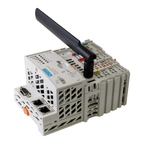
Instruction Manual NivuLink Compact 5.2 Product Overview Controller Serial interface Marking Options (Mini-WSB) LED Indicators – System Reset button (in hole) LED indicators – Mobile radio network status LED Indicators – Power Supply Feed-in section (fixed component of controller, cannot be removed) Analogue input clamp NLC07504530 (only for NLC0CLOG, NLC0CLOGP and NLC0CLOGS) 10 Digital input clamp NLC07501405 (only for NLC0CLOG, NLC0CLOGP and NLC0CLOGS) 11 Analogue output clamp NLC07505520 (only for NLC0CLOGP) -
Page 21: Device Id
5 Product Specification 5.3 Device ID 5.3.1 Labelling The front labelling includes: • device designation, • name of the display elements, connections and control elements, • serial number with hardware and firmware version. The side labelling includes: • manufacturer's identification, •... -
Page 22: Id Plate
Instruction Manual NivuLink Compact 5.3.2 ID Plate The ID plate is fixed to the controller enclosure and contains the following information: • Postal address of NIVUS GmbH • Article Number • ID number The first 4 digits of the ID number correspond with the manufacturing date (year and week no.) of the completed unit, e. -
Page 23: Led Indication Field Bus/System
5 Product Specification 5.4 LED Indication Field Bus/System Status-LED S4 System status Status-LED S3 PLC program status Status-LED S2 Internal data bus status Status-LED S1 Module status Data service status Without function Network status Status of connection to communica- tions hub Fig. -
Page 24: Data Service Status
SIM card secured by PIN Flashing red, flash code 1-4 SIM card secured by PUK Flashing red, flash code 2-1 Modem not available, contact NIVUS hotline Tab. 5-3 LED NET: Network status Page 24 NivuLink Compact - Rev. 03 / 21.09.2021... -
Page 25: System Status
Flashing yellow/green Load above threshold value 1 Yellow Runtime system in debug condition (break point, single step, single cycle) No runtime system loaded, contact NIVUS hotline Tab. 5-5 LED RUN: Program status NivuLink Compact - Rev. 03 / 21.09.2021 Page 25... -
Page 26: Internal Data Bus Status
5.4.8 Connection Status to Communication Hub Der Controller checks every 3 minutes whether there is a data connection to NICOS or to the NIVUS WebPortal available. The USR-LED indicates the connection status. Can be used for diagnostic purposes on site. -
Page 27: Mode Selector Switch
5 Product Specification 5.5 Mode Selector Switch Fig. 5-5 Mode selector switch Position Switch Function Mode Latching Normal operation e!RUNTIME applications running STOP Latching Stop All e!RUNTIME applications stopped RESET Momentary Reset warm boot: actions > 2 - < 7 seconds Reset cold boot: actions >... -
Page 28: Input Terminal Clamps
Instruction Manual NivuLink Compact 5.6 Input Terminal Clamps (Only for NLC0CLOG, NLC0CLOGP and NLC0CLOGS) Error AI 1 Error AI 3 AI 1 Ground AI 3 Ground Error AI 2 Error AI 4 Data contacts 10 AI 2 11 Ground 12 AI 4 13 Ground 14 Power jumper contacts All specified ground potentials relate to the same... -
Page 29: Output Terminal Clamps
5 Product Specification 5.7 Output Terminal Clamps (Only for NLC0CLOGP) Function AO 1 AO 1 Shield Function AO 2 Data contacts AO 2 24 V Shield 10 Power jumper contacts Fig. 5-8 Analogue output clamp NLC07505520 Status DO 1 … DO 8 DO 1 DO 3 DO 5... -
Page 30: Specifications
Instruction Manual NivuLink Compact 6 Specifications 6.1 Device Data Controller: Width 102.5 mm Height 100 mm Depth (as of carrier rail top edge) 71.9 mm Weight 288 g Tab. 6-1 Technical data – device data controller Analogue input clamp NLC07504530 (only for Art. NLC0CLOG, NLC0CLOGP and NLC0CLOGS) Width 12 mm... -
Page 31: System Data
Push-push mechanism, sealable cover lid Type of memory card SD and SDHC up to 32 GB (all guaranteed properties are valid only in connection with the NIVUS memory card NLC075808790.) Tab. 6-6 Technical data – System data 6.3 Power Supply DC 24 V (SELV/PELV, −25 …... -
Page 32: Clock
Instruction Manual NivuLink Compact Buffer for system power supply! The system power supply must be buffered to bridge power outages. As the power de- mand depends on the respective node configuration, buffering is not implemented inter- nally. To achieve power outages of 1 ms to 10 ms according to IEC61131-2, determine the buf- fering appropriate for your node configuration and structure it as an external circuit. -
Page 33: Mobile Phone Modem
6 Specifications 6.6 Mobile Phone Modem Communication Technology GSM / Edge / UMTS / HSPA+ / LTE LTE Category Cat 4 (150Mbps (DL) / 50Mbps (UL)) Frequency Band GSM Dual Band (B3 / B8), E-UTRA Bands (B1 / B3 / B5 / B7 /B8 / B20 / B38 / B40 / B41) Services GPRS connection to the Internet... -
Page 34: Analogue Input Clamp Nlc07504530
Instruction Manual NivuLink Compact 6.9 Analogue Input Clamp NLC07504530 (Only for Art. NLC0CLOG, NLC0CLOGP and NLC0CLOGS) Number of analogue inputs Total number of channels (input terminals) Signal type Current Current signal type DC 0 … 20 mA Sensor connection 4 x (2-wire) Max. -
Page 35: Digital Input Clamp Nlc07501405
6 Specifications 6.10 Digital Input Clamp NLC07501405 (Only for Art. NLC0CLOG, NLC0CLOGP and NLC0CLOGS) Number of digital inputs Total number of channels (input terminals) Signal type Voltage Current signal type DC 24 V Sensor connection 16 x (1-wire) Input characteristic positive-switching Input filter (digital) 3 ms... -
Page 36: Analogue Output Clamp Nlc07505520
Instruction Manual NivuLink Compact 6.11 Analogue Output Clamp NLC07505520 (Only for Art. NLC0CLOGP) Number of analogue outputs Total number of channels (output terminals) Signal type Current Current signal type DC 0 … 20 mA Actuator connection 2 x (2-wire) Resolution [Bit] 12 Bit Data width 2 x 16 Bit data;... -
Page 37: Digital Output Clamp Nlc07505300
6 Specifications 6.12 Digital Output Clamp NLC07505300 (Only for Art. NLC0CLOGP) Number of digital outputs Total number of channels (output termi- nals) Signal type Voltage Signal type voltage DC 24 V Actuator connection 8 x (1-wire) Output characteristics positive-switching Output current per channel 0.5 A Output current short-circuit proof... -
Page 38: Installation
Instruction Manual NivuLink Compact 7 Installation 7.1 Installation Position Along with horizontal and vertical installation, all other installation positions are allowed. Use an end stop clamp in the case of vertical mounting! In the case of vertical assembly an extra end stop has to be mounted underneath the field- bus node as an additional safeguard against slipping. - Page 39 7 Installation NLC0CLOGP Height 100 mm Width controller 102.5 mm Width 3 input clamps (2 x analogue, 1 x digital) 36 mm Width 2 output clamps (1 x analogue, 1 x digital) 24 mm Width bus terminal clamp 12 mm Total width 174.5 mm Fig.
- Page 40 Instruction Manual NivuLink Compact NLC0CLOGS Height 100 mm Width controller 102.5 mm Width 2 input clamps (1 x analogue, 1 x digital) 24 mm Width bus terminal clamp 12 mm Total width 138.5 mm Fig. 7-3 Dimensions NLC0CLOGS (top view) Page 40 NivuLink Compact - Rev.
- Page 41 7 Installation NLC0CS70 and NLC0CNF0 Height 100 mm Width controller 102.5 mm Width bus terminal clamp 12 mm Total width 114.5 mm Fig. 7-4 Dimensions NLC0CS70 and NLC0CNF0 (top view) Depth with antenna 117.0 mm Depth controller 71.9 mm Depth controller as of carrier rail top edge 64.7 mm Depth clamp 67.8 mm...
-
Page 42: Mounting Onto Carrier Rail
Instruction Manual NivuLink Compact 7.3 Mounting onto Carrier Rail All components of the system can be snapped directly onto a mounting rail according to EN 50022 (TS 35, DIN Rail 35). Do not use any third-party carrier rails without approval by WAGO! WAGO supplies standardised carrier rails that are optimal for use with NivuLink Compact. -
Page 43: Spacing
7 Installation 7.4 Spacing The following distances between adjacent components, cable conduits, enclosure and frame sides must be maintained for the complete fieldbus node: Fig. 7-6 Distances field bus node – adjacent objects The spacing • creates room for heat transfer, installation or wiring, •... -
Page 44: Mounting Sequence
Instruction Manual NivuLink Compact 7.5 Mounting Sequence Risk of personal injury CAUTION through sharp-edged blade contacts. • Handle terminal clamps with care. Basic mounting information: • Snap NivuLink Compact controller and terminals directly onto a carrier rail according to EN 50022 (TS 35). •... -
Page 45: Mounting Controller
7 Installation 7.6 Mounting Controller CAUTION Risk of equipment damage due to working on live systems. • Disconnect equipment from mains power prior to working on the devices. Top view locking disc Fix lock Release lock Nose of locking disc Releasing strap Fig. -
Page 46: Installation
The sensitive electronic components inside the unit can be damaged by static electricity which can impair the device's performance or even cause it to fail. NIVUS GmbH recommend the following steps to prevent damage to the device due to electrostatic discharge: •... -
Page 47: Connect Conductor To Cage Clamp
8 Installation 8.3 Connect Conductor to CAGE CLAMP® CAUTION Select conductor cross sections as required for current load! The current consumed for field-side supply may not exceed 10 A. The wire cross sections must be sufficient for the maximum current load for all of the input/output terminal clamps to be supplied with power. -
Page 48: Power Supply Concept
Instruction Manual NivuLink Compact 8.4 Power Supply Concept 8.4.1 Protection of the Electronics Power Supply CAUTION Power electronic components only with appropriate protection measures! Power the electronic components of the controller only through connectors 1 and 5 using a 2 A slow-blow fuse. Higher currents may damage the electronic components. Connector Name Description... -
Page 49: Equipotential Bonding
8 Installation 8.4.2 Equipotential bonding For equipotential bonding use a potential supply module! If you wish to use the lower power contact for equipotential bonding e.g. between screen connections and you need an extra terminal for such a potential use an additional WAGO Potential Supply Module 750-601/ 602/ 610 downstream of the WAGO Power Supply Filter 750-626. -
Page 50: Wiring Examples
Instruction Manual NivuLink Compact Observe during installation: • Always connect analogue inputs in "Z" shape AI 1 AI 2 Ground Ground AI 3 AI 4 Fig. 8-4 Connect analogue inputs 8.5.1.2 Wiring Examples Fig. 8-5 Connecting a 2-wire probe (e.g. pressure probe, i-Sensor) to NLC0CLOG Fig. -
Page 51: Screening
8 Installation 8.5.1.3 Screening Common The use of screened cables reduces electromagnetic influence and hence improves the sig- nal quality. Measurement errors, data transmission errors and errors due to overvoltage can be avoided. Connect cable screen to ground potential! Consistent screening is absolutely necessary to guarantee technical specifications regar- ding the measurement accuracy. - Page 52 Instruction Manual NivuLink Compact WAGO Screen Connection System The WAGO Screen Connection System consists of screen spring connections, buses and various mounting bases. These can be used for many different mounting tasks. Fig. 8-7 Example WAGO Screen Connection System Fig. 8-8 Using the WAGO Screen Connection System Page 52 NivuLink Compact - Rev.
-
Page 53: Digital Inputs
8 Installation 8.5.2 Digital Inputs DI 13 – DI 16: Digital inputs with counter function Fig. 8-9 Wiring diagram digital inputs Note: The potential must be the same as that of the field supply voltage. 8.5.3 Analogue Outputs (Only for Art. NLC0CLOGP) Fig. -
Page 54: Digital Outputs
Instruction Manual NivuLink Compact 8.5.4 Digital Outputs (Only for Art. NLC0CLOGP) Fig. 8-11 Wiring diagram digital outputs 8.6 NLC0CS70 Communication options of the NLC0CS70 device: Communication Partner ETHERNET Configuration Interface S7 PLC with defined address range in DB100 Port X1 See the following infor- mation Max. - Page 55 DB100_DBB3.7 toggles within one minute, i.e. changes the state between 0 and 1 (01010101…). If the status does not change for more than one minute, a connection error to the PLC is reported on the NIVUS WebPortal via Collection 0 Bit 6. NivuLink Compact - Rev. 03 / 21.09.2021...
-
Page 56: Nlc0Cnf0
• have connected the electronics and field-side power supply (see chap- ter 8.4), • have mounted the bus terminal clamp (NIVUS Art-No. NLC07506000, see Chapter 7.5), Page 56 NivuLink Compact - Rev. 03 / 21.09.2021... - Page 57 9 Commissioning • have performed appropriate potential equalisation at your machine/system (see Chapter 8.4.2) and • have performed screening properly (see chapter 8.5.1.3). Activate Controller and the connected Terminals: • Activate the power supply on the power adapter. The power supply LEDs (see Fig.
-
Page 58: Network Settings
There are 2 options to achieve this: Option 1 (recommended by NIVUS): 1. Determine the IP address of the host PC (see Chapter 9.3.2). 2. Adjust the IP address of the host PC to the pre-set IP address of the controller if re- quired (see Chapters 9.3.1... -
Page 59: Determine Ip Address Of The Host Pc
9 Commissioning 9.3.2 Determine IP Address of the Host PC In order to get access to the controller it is necessary to determine the IP address of the host PC. The procedure required for the Microsoft Windows® operating system is described be- low. -
Page 60: Adjusting The Ip Address Of The Host Pc
Instruction Manual NivuLink Compact 9.3.3 Adjusting the IP Address of the Host PC The following procedure describes how to adjust the IP address of the host PC to the IP address of the controller in the Microsoft Windows® operating system. Procedure: 1. -
Page 61: Deactivate / Restart Controller
9 Commissioning 9.4 Deactivate / Restart Controller Deactivate Controller: • Power supply:Deactivate. Restart Controller: 1. Set the mode switch to RUN or STOP. 2. Press the Reset key (RST) longer than 1 second but less than 8 seconds. Correct execution is indicated by all LEDs flashing green briefly. 1. -
Page 62: Configuration Via Web Based Management (Wbm)
Web-Based Management (WBM) serves to configure the controller. You can access the WBM using an Internet browser. NIVUS recommend using Google Chrome. In the following sections you can find any relevant information for the commissioning of the NivuLink Compact by using WBM. -
Page 63: Call Up Wbm
10 Configuration via Web Based Management (WBM) 10.2 Call Up WBM Prerequisite: • The controller is active (see Chapter 9.2). Procedure: 1. Connect the controller to your PC and the ETHERNET network by using ETHERNET interface X1. If X1 is occupied (e. g. for NF or DSL router): use a DIN rail switch. 2. -
Page 64: Wbm Start Screen
Instruction Manual NivuLink Compact If WBM should not start: • Make sure that your Internet browser settings enable to bypass the proxy server for local addresses. • Verify whether your PC is within the same subnet as the controller. 10.3 WBM Start Screen The figure below gives an example on the layout of the WBM browser screen. -
Page 65: Change Ip-Address Of The Nivulink Compact
10 Configuration via Web Based Management (WBM) 10.4 Change IP-Address of the NivuLink Compact You can change the pre-set IP address of the NivuLink Compact to that of your existing net- work if required. In such a case assign a new IP address to the X1 ETHERNET interface. Important Note If you change the IP address of the controller, communication with S7 PLCs, NivuFlow transmitters and NivuCam is not possible. -
Page 66: Communication With Nivuflow Transmitters
Instruction Manual NivuLink Compact 11 Communication with NivuFlow Transmitters You can use all NLC devices for communication with NivuFlow transmitters. The maxi- mum possible extent of use is optionally • 3 NivuFlow transmitters with 3 measuring points each • or 6 NivuFlow transmitters with 1 measuring point each The values below are transmitted: •... -
Page 67: Setting Parameters Nivuflow
11 Communication with NivuFlow Transmitters 11.2 Setting Parameters NivuFlow Set the TCP/IP parameters on the NivuFlow transmitters 1 - 6 as follows (for example, see the following illustration): Device IP Address Subnet Mask Gateway DNS primary DNS se- condary NivuFlow 1 192.168.1.11 255.255.255.0 192.168.1.111... -
Page 68: Configuration Nivulink Compact: Web Visualisation
Instruction Manual NivuLink Compact 11.3 Configuration NivuLink Compact: Web Visualisation 11.3.1 Call up the Web Visualisation Prerequisites: • The controller is active (see Chapter 9.2). • The controller is connected to your PC via ETHERNET interface X1 and the ETHER- NET network. -
Page 69: Login
Red = no connection Show: Opens the unit information with the current measurement data, provided there is a connection to the NivuFlow Resets the configuration, i.e. all connections between NLC and NIVUS WebPortal are dis- connected Opens the login mask Fig. -
Page 70: Configure The Nlc For The Use Of Nivuflow Transmitters
Close the browser tab Important Note Data transmission from the NivuFlow to the NIVUS WebPortal is only possible if there is a connection between the NivuLink Compact and the NIVUS WebPortal as well as between the NivuLink Compact and the NivuFlow. -
Page 71: Nivus Webportal
12 NIVUS WebPortal NIVUS WebPortal is a data management system for storage and provision of measurement data. The measured data are transmitted from NivuLink Compact to the NIVUS WebPortal as standard. This chapter provides all relevant information required to successfully operate the NivuLink Compact (NLC) in combination with the NIVUS WebPortal. -
Page 72: Verify Connection To Nivus Webportal
NivuLink Compact 12.2 Verify Connection to NIVUS WebPortal The USR-LED on the NivuLink Compact indicates the status of the connection to the NIVUS WebPortal (see Chap. 5.4.8). The procedure below describes how to determine the connec- tion status in the NIVUS WebPortal. -
Page 73: Edit Process Variable
12 NIVUS WebPortal 12.3.1 Edit Process Variable Prerequisite: • The NIVUS WebPortal is open and you are logged in as administrator. • Connection between NLC and NIVUS WebPortal is established. Procedure: 1. In measurement point overview select the measurement point linked with the NLC. -
Page 74: Configuration Options Or Process Variables
Select option window Opens a configura- Configure value, e.g. limit value tion window Deletes selected op- tion Checkbox Activate or deactivate Tab. 12-1 NIVUS WebPortal: overview on options to edit process variables Page 74 NivuLink Compact - Rev. 03 / 21.09.2021... -
Page 75: Accessories And Extensions
13 Accessories and Extensions 13 Accessories and Extensions 13.1 NIVUS Accessories and Extensions The following accessories and extensions can be purchased from NIVUS. Accessories: Art.-No. Description NLC075808790 SD memory card for NivuLink Control, 2 GB ZUB0ANT01 Antenna GSM & GPRS & LTE, omni-directional, SMA male, ben-... -
Page 76: Wago Accessories
Instruction Manual NivuLink Compact 13.2 WAGO Accessories The following accessories can be purchased from WAGO. WAGO Kontakttechnik GmbH & Co. KG Phone: +49 571 887 4433 orderservice.de@wago.com End Stops: Order-No. Description 249-116 End stop for DIN 35 rail, 6 mm wide 249-117 End stop for DIN 35 rail, 10 mm wide Tab. -
Page 77: Maintenance And Cleaning
In addition to annual maintenance NIVUS recommend having the measurement system com- pletely be inspected by a member company of the NIVUS group after 10 years the latest. Generally the system inspection is a basic measure that contributes to improve operational reliability and to increase the lifetime. -
Page 78: Dismantling
Instruction Manual NivuLink Compact 15 Dismantling CAUTION Risk of personal injury through sharp-edged blade contacts. • Handle input terminals and bus terminal clamps carefully. CAUTION Risk of equipment damage due to working on live systems. • Disconnect equipment from mains power prior to working on the devices. Top view locking disc Fix lock Release lock... -
Page 79: Disposal
Observe the local laws and regulations on disposal. NIVUS GmbH is registered with the EAR, therefore public collection and return points in Germany can be used for disposal. -
Page 80: Index
Disclaimer ..........12 Setting up communication ....... 66 Dismantling ..........78 NivuLink Compact, Overview ....20 Disposal ..........79 NIVUS WebPortal ........71 Duties of the Operator ......16 Access Data ..........71 Call Up ............ 71 Download handbook ....... 71 Process Variables ........ - Page 81 Index Device data ..........30 Digital input clamp ........35 Requirements for the Personnel .... 17 Digital output clamp ........ 37 Reset function Environmental conditions ......33 Cold Start ..........61 ETHERNET..........32 Warm Start ..........61 Field wiring ..........33 Reset Function ........
-
Page 82: Eu Declarations Of Conformity
The EU Declarations of Conformity in this chapter apply to the NivuLink Compact product fa- mily. Geräte, Erweiterungen und Zubehör der NivuLink-Compact-Familie werden von der WAGO Kontakttechnik GmbH & Co. KG hergestellt. The tables below assign the NIVUS article numbers to the according WAGO article numbers. NIVUS Art.-No. NIVUS Name WAGO Art.-No.
Need help?
Do you have a question about the NivuLink Compact NLC0CLOG and is the answer not in the manual?
Questions and answers