Advertisement
Quick Links
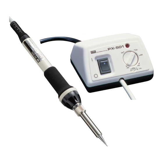
PX-501
取扱説明書
I NSTRUCTION MANUAL
PX-501
このたびは、 goot ステーション型温調は
んだこて PX-501(AS)/601(AS) をお買い上
げいただきまして誠に有難うございます。
正しくお使いいただくため、 この説明書を
よくお読みになった上でご使用ください。
AS シリーズは静電対策 (Anti-Static) モデルです
目次
■ 1
ご使用前に必ずお読みください。
■ 2
特長および特性・仕様
■ 3
各部の名称と働き
■ 4
ご使用方法
4-1
PX-501 の使用方法
4-2
PX-601 の使用方法
■ 5
保守と故障対策
5-1
こて先の交換方法
5-2
ヒーターの交換方法
5-3
温度校正の方法
5-4
リーク電流/絶縁抵抗の測定
5-5
故障と原因対策
■ 6 分解図/交換部品
2. 特長および特性・仕様
FEATURES / SPECIFICATIONS
PX-601(AS)
●温度設定
250〜450℃の間で温度設定ができます。 250℃で±10%、 300℃〜
450℃設定で±5%程度の温度差が生じる場合があります。 正確な温度を
設定する必要がある場合は、 こて先温度計で温度調節を行ってください。
測定方法 5-4 を必ずお読みください。
●リーク電流/絶縁抵抗測定端子付
リーク電流/絶縁抵抗の測定が容易にできる端子付。 デリケートな
作業にも安心してご使用いただけます。
●保護カバー
温度調整つまみ、 リーク電流/絶縁抵抗測定端子部にはロック機能
付の保護カバーを採用。 つまみ、 端子の保護と同時に確実な温度管
理作業が可能となります。 (PAT.)
●クイックスタート
電源 ON から設定温度まですばやい立ち上がりのクイックスタート
回路採用。 (PAT.)
PX-501(AS)
●温度設定
250 〜 450℃の間で温度設定ができます。250℃で ±10%、300℃〜
450℃設定で ±5%程度の温度差が生じる場合があります。正確な温度を
設定する必要がある場合は、こて先温度計で温度調節を行ってください。
●クイックスタート
電源 ON から設定温度まですばやい立ち上がりのクイックスタート
回路採用。 (PAT.)
ブロックダイヤグラム / BLOCK DIAGRAM
仕 様 / SPECIFICATIONS
型 番
PX-601(AS)
PX-501(AS)
定格電圧
100V 50/60Hz
消費電力
85W
こて部電圧/電力
100V AC /80W
設定温度範囲
250~450˚C
絶縁抵抗 (500V DC)
100MΩ 以上
本体
W48:H31:D130 ( mm)W100:H57:D85 ( mm)
サイズ
こて部
全長 195mm (コー ドアーマー除く)
本体
75g (コー ド除く)
266g(コー ド除く)
重量
こて部
41g (コー ド除く)
こて部〜制御部間コー ド長
1.2m (3 芯コー ド)
電源コー ド長
1.5m (3 芯コー ド ・ アースピンプラグ)
無負荷時温度リ ッ プル
± 5℃
リーク電圧
2mV 以下
アース抵抗
2 Ω以下
温度制御方式
センサーフ ィ ー ドバッ ク (ON-OFF 制御)
All manuals and user guides at all-guides.com
/ PX-601
(AS)
(AS)
PX-601
Thank you for buying the goot
PX-501
/601
. Before using,
(AS)
(AS)
please read this instruction manual
carefully.
AS Series (Anti-Static models)
INDEX
■1 RULES FOR SAFE OPERATION
■2 FEATURES / SPECIFICATIONS
■3 NAME OF PARTS AND DESCRIPTIONS
■4 OPERATING PROCEDURES
4-1 HOW TO OPERATE PX-501
4-2 HOW TO OPERATE PX-601
■5 MAINTENANCE AND
TROUBLESHOOTING GUIDE
5-1 TIP REPLACEMENT
5-2 HEATER REPLACEMENT
5-3 TEMPERATURE CALIBRATION
5-4 LEAKAGE CURRENT / INSULATION
RESISTANCE VALUE MEASUREMENT
5-5 TROUBLESHOOTING GUIDE
■6 DISASSEMBLY ILLUSTRATION AND
REPLACEMENT PARTS
● Temperature setting range
The temperature can be variably set from 250°C to 450°C .
Temperature differences may be observed. (±10% at 250°C
temperature setting,±5% at 300°C 450°Csetting ) Use tip
thermometer when the accurate temperature is required.
● Leakage current / insulation resistance measuring terminal.
Please refer to 5-4
(PX-601(AS))
The PX-601 is equipped with a measuring terminal allowing easy
measurement of leakage current and insulation resistance.This
ensures precision components will not be damaged when soldering.
● Protective cover (PX-601(AS))
A p rote c tive c ove r,s e c u re d wi th a s c rew, p reve nt s a ny
accidental temperature and other setting changes.(PAT.)
● Quick start
A quick heat up circuit (PAT.) increases the speed at which the
soldering station reaches set temperatures.
● Temperature setting range
The temperature can be variably set from 250°C to 450°C .
Temperature differences may be observed. (±10% at 250°C
temperature setting,±5% at 300°C 450°Csetting ) Use tip
thermometer when the accurate temperature is required.
● Quick start
A quick heat up circuit (PAT.) increases the speed at which the
soldering station reaches set temperatures.
TIP TEMPERATURE STABILITY
Set at 450℃
Set at 350℃
*
この特性表はこて先の先端に熱電対をつけて測定し、 作業は 5mm 角のランドへ連続しては
んだ付けし、 測定したものです。 (こて先 / PX-60RT-B)
*
Thermo-couple fitted to the tip. Solder melted constantly on 5X5 mm PCB trace
layout. (Tip : PX-60RT-B)
MODEL
PX-601(AS)
PX-501(AS)
Voltage
110, 220-240V AC
Power Consumption
85W
Soldering Unit Voltage
110, 220-240V AC
Temp. Setting Range
250-450°C
Insulation Resistance
Over 100MΩ
Control Unit
W48 : H31 : D130(mm)
W100 : H57 : D85(mm)
Dimensions
Soldering Unit
195mm
Control Unit
75g (w/o cord)
266g (w/o cord)
Weight
Soldering Unit
41g (w/o cord)
Control Unit to Soldering Unit Cord Length
1.2m
Power Cord Length
1.5m (3 core cord) / ground plug
Ripple Temp. without Load
±5˚C
Leak Voltage
Under 2mV
Ground Resistance
Under 2Ω
Temp. Control System
Sensor feed back (ON-OFF control)
1. 使用する前に必ずお読み下さい
RULES FOR SAFE OPERATION
警告 /
WARNING
●火傷の危険をなくすために
こての発熱部、 その近接部は高温になります。
使用中これらの部品に直接、 手や肌が触れな
い様にしてください。
●火災の危険をなくすために
燃えやすい物の近くで使用しないでください。
火災の原因になります。
●感電の危険をなくすために
必ず3ピンプラグのアースピンを接地してください。
メンテナンス、 ヒューズの交換、 または本体ケースを外す必
要が生じた時は、 必ず電源スイッチを切り、 電源プラグをコ
ンセントから抜いて行ってください。電源コードやこて部コ
ードにキズ、 損傷等がある場合は火災、 感電等の危険があり
ますのですぐに使用を中止し、 電源プラグを抜いてください。
警告 ASシリーズの取扱い /
WARNING FOR
●感電防止および静電対策の為に、電源プラグのアースピン
を必ずアース接地してください。アース接地をしない場合
は感電の危険があります。
●静電対策の為、特殊な仕様となっていますの
でご注意ください。特に導電性材料を使用し
ていますので、電源ラインとの接触で事故を
起こす場合がありますのでご注意ください。
注意 /
CAUTION
●
火災や火傷防止のため、 必ずこて台を使用してください。 こて台
は goot ST-77、 ST-27 をおすすめします。 当社製以外のこて台を
使用すると、 こてが破損する場合があります。
●
危険ですから小さなこどものそばでは使用しないで
ください。 また、 使用後はいたずら防止のため、 こど
もの手の届かない場所に保管してください。
●
定格以上の電圧を加えないでください。 ヒーターが
過熱し、 火災の危険があります。
●
風呂場など、 水分や湿気の多い場所では絶対に使用
しないでください。 感電する恐れがあります。
●
プラグはコンセントの電流定格を確かめてから、 根
元まで差し込んでください。 使用後、 必ずプラグをコ
ンセントから抜いてください。 コードではなく、 必ずプラグをつま
んで抜いてください。
ご使用に際して /
NOTE
●
使用後は水に漬けて急冷すると故障の原因になりますので、 自然
に冷やしてください。
●
こて先は使用状況により、 酸化物等が付着してはんだがのりにく
くなることがあります。 ご使用の際はこて先クリーナー等を併用
し、 常にこて先がクリーンな状態でお使いください。
●
こて先は特殊メッキを施してしてありますので、 表面の酸化物を
取り除く際はメッキを剥がさないようにしてください。
●
こて先やセラミックヒーターは衝撃で破損しますので、叩きつけ
たり落下させないように注意してください。
●
鉛フリーはんだを使用すると鉛入りはんだを使用した時と比べ
て、こて先の寿命が低下する場合があります。
太洋電機産業株式会社
TAIYO ELECTRIC IND.CO.,LTD.
ホームページ/電子メールのアドレス HomePage: www.goot.co.jp E-mail: info@goot.co.jp
"goot" ブランドは太洋電機産業株式会社の登録商標です。
"goot" is a registered trademark of TAIYO ELECTRIC IND.CO.,LTD.
3. 各部の名称と働き
NAME OF PARTS & DESCRIPTIONS
PX-501
PX-601
ステーション部
①電源スイッチ
主電源スイッチです。作業を中断する時、 長時間使用しない時
は必ず OFF にしてください。
②ヒーター通電ランプ
ヒーターが通電中に点灯します。 こて先温度が設定温度に達す
ると点滅し (ON-OFF 制御) 使用可能であることを知らせます。
③温度設定つまみ
こて先温度を設定します。
④温度校正用ボリューム
温度校正用ボリュームです。 ヒーター、 こて部を交換した際に
このボリュームで温度校正をおこなってください。
⑤リーク電流/絶縁抵抗測定用端子 (PX-601 のみ)
リーク電流、 絶縁抵抗を測定する端子です。 こて先とこの端子
間でリーク電流/絶縁抵抗を測定してください。
⑥スライドカバー (PX-601 のみ)
温度設定ボリュームで温度設定後、 容易に設定が変わらない様
に保護するカバーです。 作業中はカバーをしたままご使用くだ
さい。
⑦スライドカバーロックねじ (PX-601 のみ)
スライ ドカバーが動かないようにロックするためのねじです。
こて部
⑧グリップラバー
⑨アダプター固定ねじ
ヒーター交換を行う際にはこのねじを緩めてアダプターを外し
てください。
⑩ナッ ト
こて先交換の際にはこのナッ トを外して交換します。
⑪こて先
特殊コーティングを施した専用こて先です。豊富な替えこて先
を取り揃えています。 (6. 分解図・交換部品参照)
●
To avoid serious burns
Never touch the tip, heater barrel and collar
until they cool down. The soldering station
should never be left unattended while it is hot.
●
To prevent fires
K e e p t h e s o l d e r i n g s t a t i o n a w a y f ro m
flammable substances and materials in the
work area.
●
To prevent electric shock
Plug it into a grounded pin type receptacle to properly
ground it. Be sure to turn the main switch OFF and unplug
the unit before doing the maintenance, replacing parts
and/or removing the housing. Never use your soldering
iron if the power cord and/or soldering unit cord is
damaged, or fires or electric shock may occur.
AS SERIES
The PX-501AS, PX-601AS are anti-static models. Be sure to properly
ground the soldering station using a grounded receptacle to prevent
electrical shocks and anti-static. If it is not properly grounded
electrical shocks will occur.
As the soldering station uses conductive materials,
please be careful not to touch any electrical power
source or a serious injury will result.
● Be sure to use the goot ST-77, ST-27 soldering iron stand to
prevent serious burns or fires. If any other stand
is used, the soldering unit may be damaged.
●
Keep children and bystanders away from the
soldering station.
●
Connect to the specified power supply. The
power voltage for this soldering iron is indicated
on the back of control unit. Never plug the
soldering iron into any other voltage.
●
Do not use the soldering iron in damp or wet
locations or expose it to rain, including outside to
prevent electrical shocks.
●
After checking that the voltage is correct. Plug in fully in
the outlet unplug when not in use. (Pull out the plug when
unplugging. Never yank the cord.)
●
When oxidized particles stick to the tip, the wettability is
reduced. Keep the soldering iron tip clean using tip cleaner for
optimum performance.
●
Do not use water to cool the tip down or it may cause damage
to the heater. Allow it to cool naturally.
●
Do not use a file to clean the tip or the
long –life tip may be damaged.
●
Do not give a hard shock to your
soldering unit. Dropping on hard
shock could result in damage to the
heater and tip.
●
When compared to use with solder containing lead, tip life may
be shorter when using lead-free solder.
お客様相談窓口
東京 03(3832)1774
大阪 06(6644)3508
広島 084(951)9010
新潟 0256(35)5379
Customer service: Please contact your nearest distributor
JAN 2013 Printed in Japan A0690AM00
DNP
グリ ップラバー
GRIP RUBBER
Control Unit
①
Main power switch
Be sure to turn OFF when not in use.
②
Heater lamp
LED lamp lights when the heater is ON. When the set
temperature is reached, the lamp starts to flicker, signaling
that the soldering station is ready to use.
③
Temperature setting dial
Turn the dial to the desired temperature .
④
Temperature calibration knob
After replacing the tip and/or heater, temperature calibration
is required.
⑤
Measuring terminal (PX-601(AS))
For measuring leakage current and insulation resistance.
⑥
Protective cover (PX-601(AS))
Prevents any accidental temperature and other setting
changes.
⑦
Lock screw (PX-601(AS))
Prevents the protective cover from accidentally opening.
Soldering Unit
⑧
Grip rubber
⑨
Adapter fixing screw
Loosen the fixing screw and remove the adapter when
replacing the heater.
⑩
Collar
Loosen the collar when replacing the tip.
⑪
Tip
The tip is covered in a special plating. Tips with various
shapes are available.
Advertisement

Related Manuals for Goot PX-501


Summary of Contents for Goot PX-501
- Page 1 を必ずアース接地してください。アース接地をしない場合 ground the soldering station using a grounded receptacle to prevent は感電の危険があります。 electrical shocks and anti-static. If it is not properly grounded このたびは、 goot ステーション型温調は Thank you for buying the goot ●静電対策の為、特殊な仕様となっていますの electrical shocks will occur. んだこて PX-501(AS)/601(AS) をお買い上 PX-501 /601 . Before using,...
- Page 2 *3 ピン用のコンセントが無い場合は 3 ピン -2 ピン変換プラグ after replacing the fuse. P-10 ( 別売)をご使用ください。 6. 分解図・交換部品 / 4-1PX-501(AS) の使用方法 HOW TO OPERATE PX-501(AS) DISASSEMBLY ILLUSTRATION AND REPLACEMENT PARTS STEP 1. 温度設定つまみ③で希望温度に設定してください。 STEP 1. Set the temperature setting dial to the desired temperature.
Need help?
Do you have a question about the PX-501 and is the answer not in the manual?
Questions and answers