Table of Contents
Advertisement
Quick Links
DESCRIPTION
This bulletin describes the installation and operation of the NXTSD507HD (7") and NXTSD512HD
(12.1") touchscreen interfaces. An overview of navigation through the available data as well as device-
specific information is covered.
These optional devices allow for enhanced and expanded connectivity to the NXF4000 and PPC4000
parallel-positioning systems. This bulletin is intended to be a supplement to the specific bulletin for
any connected control. Those bulletins may be specified in this document. Please refer to those
bulletins for any specific information on installation, features, commissioning or operation of the
connected controls.
WARNING: Failure to properly install, operate, or commission the equipment
in this manual could result in significant property damage, severe injury, or
death. It is the responsibility of the owner or user to ensure that the
equipment described is installed, operated and commissioned in compliance
with this manual as well as the manuals of other system components, as
well with all applicable national and local codes.
WARNING: Boiler operation, maintenance, and troubleshooting shall only be
conducted by trained personnel. Persons troubleshooting lockouts or
resetting the control must respond properly to troubleshooting error codes as
described in this product bulletin. Jumpers being used to perform static test
on the system must only be used in a controlled manner and must be removed
prior to the operation of the control. Such tests may verify the external
controllers, limits, interlocks, actuators, valves, transformers, motors and
other devices are operating properly. Such tests must be conducted with
manual fuel valves in the closed position only. Replace all limits and interlocks
not operating properly, and do not bypass limits in interlocks. Failure to follow
these guidelines may result in an unsafe condition hazardous to life and
property.
© 2021 Carrier
NXTSD507HD, NXTSD512HD
Touchscreen Interface
Installation and Operation
TSD-4001
August 1, 2021
1
Advertisement
Table of Contents

Related Manuals for Carrier Fireye NXTSD507HD


Summary of Contents for Carrier Fireye NXTSD507HD
-
Page 1: Description
Replace all limits and interlocks not operating properly, and do not bypass limits in interlocks. Failure to follow these guidelines may result in an unsafe condition hazardous to life and property. © 2021 Carrier... -
Page 2: Table Of Contents
Miscellaneous ..............................31 Language ................................39 Screen Saver / Date ............................. 40 Network ................................41 Modbus Data Server ............................42 OVERVIEW SCREEN (BurnerLogix) ........................45 WIRING DIAGRAM SCREEN (BurnerLogix) ......................46 FAULT HISTORY SCREEN (BurnerLogix) ......................47 © 2021 Carrier... - Page 3 MOTOR SCREEN (ABB ACS550) ..........................54 SETTINGS SCREEN (ABB ACS550)........................55 BACKUP / RESTORE SCREEN (ABB ACS550) ..................... 56 REMOTE VIEWING VIA VNC PROTOCOL ......................57 CERTIFICATIONS NXTSD507HD AND NXTSD512HD ..................58 NOTICE ..................................58 WARRANTIES ................................58 © 2021 Carrier...
-
Page 4: System Information
Check the ratings in the following instructions to ensure the product is suitable for your application. Installation, commissioning or adjustment of this product MUST be carried out by personnel qualified by local, state, regional or national requirements. After installation is complete, check the product operation is as described in these instructions. © 2021 Carrier... -
Page 5: Technical Data Nxtsd507Hd
Indoor use only, IP67 face, IP40 rear Installation orientation: Landscape (horizontal) Unit dimensions faceplate: 201mm x 140mm (7.91 in. x 5.51 in.) Unit dimensions depth: 40mm (1.57 in.) Panel cutout dimensions: See mounting section for diagram Weight: 1.1 kg. (2.5 lb.) © 2021 Carrier... -
Page 6: Technical Data Nxtsd512Hd
Installation orientation: Landscape (horizontal) Unit dimensions faceplate: 313.4mm x 215.5mm (12.3 in. x 8.48 in.) Unit dimensions depth: 50mm (1.97 in.) Panel cutout dimensions: 300mm x 192mm (11.81 in. x 7.55 in.) Weight: 2.5 kg. (5.5 lb.) © 2021 Carrier... -
Page 7: Ordering Information
Modular connection cable to connect BurnerLogix to ED610, 8’ length. ED580-2 Modular connection cable to connect BurnerPRO to ED610, 2’ length. ED580-4 Modular connection cable to connect BurnerPRO to ED610, 4’ length. ED580-4 Modular connection cable to connect BurnerPRO to ED610, 8’ length. © 2021 Carrier... -
Page 8: Mounting Nxtsd507Hd
M4x0.7 thread and the posts are 25mm long. If a post and thumb nut are lost and need replacement, an M4x0.7 screw that is 10mm long can be used in combination with a washer. Post with knurled-head thumb nut © 2021 Carrier... -
Page 9: Cutout
A template is also provided on the following page that may be printed at 100% scale and used to provide a guide. © 2021 Carrier... -
Page 10: Template
Template © 2021 Carrier... -
Page 11: Mounting Nxtsd512Hd
A medium strength thread-locking compound (commonly referred to as “blue”) may be used to prevent loosening of the screws if the equipment is subject to vibration or will be in transit. Post with knurled-head thumb nut © 2021 Carrier... -
Page 12: Cutout
Cutout Use the following dimensions to mark the necessary cutout to mount the screen. The orientation of the screen is with the widest dimension horizontal. © 2021 Carrier... -
Page 13: Wiring
NXF-4100 for further clarification on terminal ratings, power supply considerations and any other issues that may not be covered in this bulletin. Refer to the table below for the required wiring connections between the connected controls and the NXF4000/PPC4000 terminal blocks screen. © 2021 Carrier... -
Page 14: Wiring
Not connected Black 18AWG Not connected Not connected Orange 22AWG 1(+), 2(+), 3(+) or 4(+) Brown 22AWG 1(-), 2(-), 3(-) or 4(-) Refer to Fireye bulletin BP-1004 for further clarification on setting up the required Modbus settings. © 2021 Carrier... - Page 15 WARNING: Use of third-party power supply is permitted, provided the power supply meets NEC CLASS 2 to protect against fire and electrical shock. WARNING: Use of third-party power supply is permitted, provided the power supply meets NEC CLASS 2 to protect against fire and electrical shock. © 2021 Carrier...
-
Page 16: Ethernet/Usb
The figures below show the connectors for Ethernet and USB. There is one Ethernet port for connecting to a network and two type-A USB ports for connecting to a keyboard, mouse or USB drive. A USB hub can be connected if needed to increase the capacity or accessibility of these ports. NXTSD507HD NXTSD512HD © 2021 Carrier... -
Page 17: Establishing Communication
PPC4000 has a different unit address when multiple controls are connected. The default unit address of 247 can be retained when there is only one control or if each is connected to a different serial port. The reason for unique unit addressing is to avoid conflicts. © 2021 Carrier... -
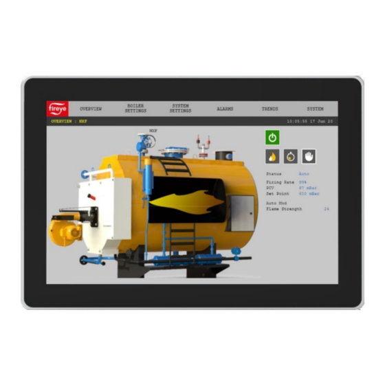
Page 18: Overview Screen (Nxf4000 And Ppc4000)
OVERVIEW. The FIREYE logo button will return to the device selection screen if multiple devices are connected. The first menu to the right of the FIREYE logo allows quickly changing the selected device, while the next menu allows navigation of parameters or options within the defined control. © 2021 Carrier... -
Page 19: Information Screen (Nxf4000 And Ppc4000)
All the same information from the home screen is available, but there are also additional tabs for more detailed status information. See Fireye bulletin NXF-4100 for additional information on NXF4000 or PPC4000 configuration and functionality. © 2021 Carrier... -
Page 20: General Settings (Nxf4000 And Ppc4000)
LOCK icon when trying to change a value. See Security control popup section SYSTEM SECURITY for additional information on how to log in. © 2021 Carrier... -
Page 21: System Settings
Pressing the right-most dropdown on the left menu bar and choosing SYSTEM SETTINGS will display the submenu options for system settings. Each of these submenu options will display a screen dedicated to a specific setting function. See Fireye bulletin NXF-4100 for additional information on NXF4000 or PPC4000 configuration and functionality. © 2021 Carrier... -
Page 22: Alarms
ALARMS Pressing the ALARMS button right menu bar will display the alarms submenu. © 2021 Carrier... -
Page 23: Active
Active alarms will appear on any screen as a red banner with a button to dismiss the alarm banner. The active alarm page accessible here will list any active alarms. Dismissing the alarm banner will not remove an active alarm from this list. © 2021 Carrier... -
Page 24: Log
The alarm log screen will show the list of alarms sorted by date. The date show is at the top of the screen and can be adjusted using the left and right arrows. Each entry is date and time stamped. Alarms for the past 30 days are stored. © 2021 Carrier... -
Page 25: Fault History
Fault History Pressing the right-most dropdown on the left menu bar and choosing MENU FAULT HISTORY will display the complete fault history from the NXF4000 or PPC4000. © 2021 Carrier... -
Page 26: Help
Pressing the right-most dropdown on the left menu bar and choosing MENU HELP will display the icon legend. This will help to identify what the icons designate if that is not known. See Fireye bulletin NXF-4100 for additional information on NXF4000 or PPC4000 configuration and functionality. © 2021 Carrier... -
Page 27: System
OPTIONS Miscellaneous Export for additional information. The SHUTDOWN menu option will perform a soft shutdown on the screen. If this is done, power will have to be recycled to power the screen back on. © 2021 Carrier... -
Page 28: Log
A system event log can be displayed to show not only all alarms but also every system event such as logins, etc. © 2021 Carrier... -
Page 29: Security
CONFIGURATION screen. This screen allows adding or deleting users, creating access permissions for each user as well as changing passwords. Access permission allows specific users to be able to take specific actions without having to enter a higher-level password. © 2021 Carrier... - Page 30 “Logged out” user rights to adjust parameters or click buttons. This would allow the user to reset a lockout without logging in. Note that any NXF4000 or PPC4000 parameter that requires local user security with the Commissioning, Adjust Ratio or Site passcode will still require those passcodes to be entered. © 2021 Carrier...
-
Page 31: Options
Options Pressing the OPTIONS button will allow the user to change screen options. There are multiple pages within the options – pressing the folder icon at the upper right corner will move between options pages. Miscellaneous © 2021 Carrier... - Page 32 BurnerLogix, BurnerPRO (generation four) or an ACS550, the baud rate and unit address must be manually entered. Note that the baud rates don’t have to match for devices on the same daisy chain as the baud rate is dynamically adjusted with each message sent. © 2021 Carrier...
- Page 33 If there is more than one device connected, the FIREYE logo button on the upper left corner will display an overview of all devices. Each device can then be navigated from here. © 2021 Carrier...
- Page 34 CLOSE (X) icon, then pressing the specific grid position/device. Grid boxes can be merged as well so that certain controls can be larger than others or not shown at all on the overview. All controls can also be viewed from the drop-down menu just the right of the FIREYE logo button. © 2021 Carrier...
- Page 35 For each graph, a maximum of 300 data points can be saved per pen with an interval from 1 to 600 seconds per capture. © 2021 Carrier...
- Page 36 Up to eight data points can be selected per graph. Once selected, they can be removed, or new points added if the total doesn’t exceed eight points. © 2021 Carrier...
- Page 37 Once one or more trend graphs have been configured, there will be a new menu item TRENDS that will list all the configured graphs on the submenu. © 2021 Carrier...
- Page 38 Eject USB Drive Selecting this option will unmount the USB drive and prompt that it is safe to remove. This is preferred over simply removing the drive, which may corrupt data or cause failure to recognise USB drives. © 2021 Carrier...
-
Page 39: Language
Language The selected language can be changed from this screen. © 2021 Carrier... -
Page 40: Screen Saver / Date
NXF4000 and PPC4000 units must have a year that is 2020 or later. This may result in errors that reference the device name, a parameter number and the message “Invalid Parameter”. If the device is named NXF, an example of this would be NXF.2319 Invalid Parameter. To correct, simply enter the correct date and time. © 2021 Carrier... -
Page 41: Network
Network The network settings (IP address, subnet mask, default gateway) can be set from here. These settings are used when connecting the Modbus TCP/IP server or when using the remote VNC viewing protocol. © 2021 Carrier... -
Page 42: Modbus Data Server
Modbus Data Server for how to change these settings. The Modbus server uses function code 3 for all reads and function code 6 or 16 for all writes. Writing multiple consecutive registers is allowed using function code 16. © 2021 Carrier... - Page 43 The resulting .csv files can be read with any text editor or a spreadsheet program such as Microsoft Excel. Below is an example of MBServerMap.csv, viewed using Microsoft Excel: In this case, the device named “Boiler 1” is a PPC4000 so this must also be known since there can be multiple devices present. © 2021 Carrier...
- Page 44 Register 40002 (representing “Current operational state”) can contain a value from 0 to 18. This number represents which functional state the NXF4000 or PPC4000 is in. There needs to be a definition for each value to get meaning from this register. To determine what each value means, the file EnumMap.csv is used. © 2021 Carrier...
-
Page 45: Overview Screen (Burnerlogix)
If the BurnerLogix is selected as a device, pressing the right-most dropdown on the left menu bar and choosing OVERVIEW will display the device overview screen. See Fireye bulletin BL-1001 for additional information on configuration and functionality of these controls. © 2021 Carrier... -
Page 46: Wiring Diagram Screen (Burnerlogix)
Selecting the correct programmer or model is necessary to ensure that the data shown is correct. See Fireye bulletin BL-1001 for additional information on configuration and functionality of these controls. © 2021 Carrier... -
Page 47: Fault History Screen (Burnerlogix)
If the BurnerLogix is selected as a device, pressing the right-most dropdown on the left menu bar and choosing MISC FAULT HISTORY will display the fault history screen. The internal fault history of the BurnerLogix flame safeguard is shown. © 2021 Carrier... -
Page 48: Settings Screen (Burnerlogix)
The main options are if the YZ300 annunciator is connected, as well as specifying the type of flame amplifier fitted. If the YZ300 is enabled, the specific messages for each input can be edited and this edit will show on both the YZ300 status as well as the display connected to the BurnerLogix. © 2021 Carrier... -
Page 49: Yz300 Screen (Burnerlogix)
YZ300 will display the YZ300 status screen. The first limit that does not have the green status lamp on is the source of the shutdown. In the example below, the limit “High Gas Pressure” is the first lamp out and is the source of the shutdown. © 2021 Carrier... -
Page 50: Overview Screen (Burnerpro)
If the BurnerPRO is selected as a device, pressing the right-most dropdown on the left menu bar and choosing OVERVIEW will display the device overview screen. See Fireye bulletin BP-1004 for additional information on configuration and functionality of these controls. © 2021 Carrier... -
Page 51: Wiring Diagram Screen (Burnerpro)
Selecting the correct programmer or model is necessary to ensure that the data shown is correct. See Fireye bulletin BP-1004 for additional information on configuration and functionality of these controls. © 2021 Carrier... -
Page 52: Settings Screen (Burnerpro)
MISC SETTINGS will display the settings screen. Options for the BurnerPRO can be set from this screen. These are the same options that can be set using the Config Wizard for BurnerPRO software. See Fireye bulletin BP-1004 for additional information on configuration and functionality of these controls. © 2021 Carrier... -
Page 53: Overview Screen (Abb Acs550)
If the ABB ACS550 VFD is selected as a device, pressing the right-most dropdown on the left menu bar and choosing OVERVIEW will display the device overview screen. See ABB ACS550 documentation for additional information on configuration and functionality of these controls. © 2021 Carrier... -
Page 54: Motor Screen (Abb Acs550)
If the ABB ACS550 VFD is selected as a device, pressing the right-most dropdown on the left menu bar and choosing MOTOR will display the motor data screen. See ABB ACS550 documentation for additional information on configuration and functionality of these controls. © 2021 Carrier... -
Page 55: Settings Screen (Abb Acs550)
SETTINGS will display the device settings screen. All the registers that require modification as shown in Fireye bulletin NXF-4100 can be directly modified from this screen. See ABB ACS550 documentation for additional information on configuration and functionality of these controls. © 2021 Carrier... -
Page 56: Backup / Restore Screen (Abb Acs550)
The folder icon located at the upper-right corner changes the dialog to download, where one of the saved configuration or the default Fireye 50Hz or 60Hz configuration can be loaded. © 2021 Carrier... -
Page 57: Remote Viewing Via Vnc Protocol
Note that since a VNC connection is the same at the actual screen or at a remote connection, control at the actual screen will also be disabled while a VNC viewer is connected. Individual change disabled Changes disabled popup © 2021 Carrier... -
Page 58: Certifications Nxtsd507Hd And Nxtsd512Hd
In no event shall Fireye be liable for consequential or special damages of any nature that may arise in connection with such product or part. Fireye, Inc. TSD-4001 3 Manchester Road August 1, 2020 Derry, NH 03038 www.fireye.com © 2021 Carrier...
Need help?
Do you have a question about the Fireye NXTSD507HD and is the answer not in the manual?
Questions and answers