Table of Contents
Advertisement
Quick Links
TABLE OF CONTENTS
SAFETY CONSIDERATIONS.........................................1
GENERAL..........................................................................1
ACCESSORIES.................................................................2
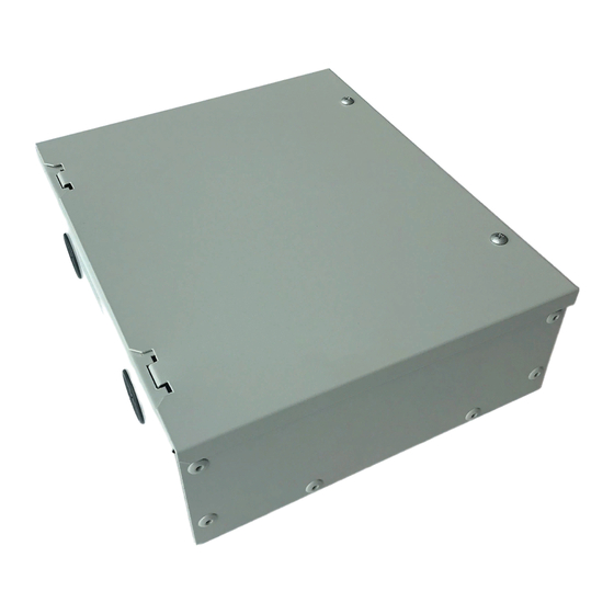
DIMENSIONS....................................................................2
DLS UNIT COMPATIBILITY.........................................2
SELECTING INSTALLATION POSITION..................3
RECOMMENDED CLEARANCES................................3
INSTALLATION...............................................................3
Installation Method..........................................................3
WIRING DIAGRAM.........................................................4
POWER WIRING..............................................................5
COMMUNICATION WIRING........................................5
AUX HEAT SIGNAL INPUT............................................2
DIP SWITCH SETTINGS.................................................5
OPERATING INSTRUCTIONS......................................6
Step -1 - Getting Started..................................................6
Step - 2 - Discovering Ductless Indoor Unit...................6
Step - 3 - Configuring the Ductless Indoor Unit..............7
COMMON QUESTIONS..................................................8
Manufacturer reserves the right to discontinue, or change at any time, specifications or designs without notice and without incurring obligations.
Catalog No. 20-40VM900010-01
Installation and Operating Instructions
Part Number 40VM900010
Printed in U.S.A.
40VM900010 DLS VRF Interface
VRF (Variable Refrigerant Flow) System
SAFETY CONSIDERATIONS
Page
Read and follow manufacturer instructions carefully. Follow all
local electrical codes during installation. All wiring must
conform to local and national electrical codes. Improper wiring
or installation may damage thermostat.
Understand the signal words - DANGER, WARNING, and
CAUTION. DANGER identifies the most serious hazards,
which will result in severe personal injury or death.
WARNING signifies hazards that could result in personal
injury or death. CAUTION is used to identify unsafe practices,
which would result in minor personal injury or product and
property damage.
Recognize safety information. This is the safety-alert symbol
(
). When this symbol is displayed on the unit and in
instructions or manuals, be alert to the potential for personal
injury. Installing, starting up, and servicing equipment can be
hazardous due to system pressure, electrical components, and
equipment location.
Note that changes or modifications of this product are not
expressly approved by the party responsible for compliance
and could void the user's authority to operate the equipment.
NOTE: This equipment has been tested and found to comply
with the limits for a Class B digital device, pursuant to Part 15
of the FCC rules. these limits are designed to provide
reasonable protection against harmful interference in a
residential installation. This equipment generates, uses, and can
radiate radio frequency energy and, if not installed and used in
accordance with the instructions, may cause harmful
interference to radio communications. However, there is no
guarantee that interference will not occur in a particular
installation.
If this equipment does cause harmful interference to radio or
television reception, which can be determined by turning the
equipment off and on, the user is encouraged to try to correct
the interference by one or more of the following measures:
Reorient or relocate the receiving antenna.
Increase the separation between the equipment and the
receiver.
Connect the equipment into an outlet on a circuit different from
that to which the receiver is connected.
Consult dealer or an experienced radio/TV technician for help.
GENERAL
The DLS VRF Interface is a communication device that allows
you to connect ductless indoor units into VRF touch screen
central controller. Ductless indoor units, any style, will be
shown as high wall unit icon on the touch screen central
controller. Ductless indoor unit can be controlled using VRF
wired controller.
Form 40VM-10SI Rev 1
Indoor Unit Interface
Pg 1
10-20
Replaces: 40VM-10SI
Advertisement
Table of Contents

Related Manuals for Carrier DLS VRF


Summary of Contents for Carrier DLS VRF
- Page 1 Consult dealer or an experienced radio/TV technician for help. GENERAL The DLS VRF Interface is a communication device that allows you to connect ductless indoor units into VRF touch screen central controller. Ductless indoor units, any style, will be shown as high wall unit icon on the touch screen central controller.
- Page 2 NOTE: All Dimensions are in inches. Fig. 1 —Dimensional Drawing DLS UNIT COMPATIBILITY Table 2 —Relevant DLS Units (Compatibility) Requires Purchase of Adapter Board and Model Number Sizes Voltage XYE Bus Compatible with DLS VRF Interface Display Board 115V 40MHHC 12,18,24 230V 115V 40MHHQ 12,18,24...
- Page 3 Read this manual carefully before installing the interface Installation Method and keep the manual for future reference. The DLS VRF 1. Use screwdriver to remove screw (2) of the box cover. Interface should be installed as close as possible to the ductless indoor unit.
- Page 4 WIRING DIAGRAM TRANSFORMER BLACK YELLOW LED1 YELLOW DEBUG ENC2 ENC1 SW7 CN54 X E Y X E Y HB HA BLACK Control port of L1 L2 auxiliary heater etc. TERMINAL ( Voltage range: 0-24V AC/DC) ( Current range: 0-1A) POWER INPUT NOTES: 1.
- Page 5 A system has 10 VRF indoor units and 2 DLS indoor units with DLS VRF Interfaces. There is no automatic addressing function for the DLS VRF Interface. If the VRF indoor units are addressed 0-9, the DLS indoor units will be 10 and 11 following the settings in Table 4.
- Page 6 Step – 2 – Discovering Ductless Indoor Unit 1. Connect ductless indoor unit to touch screen central 1. Press the “Install” icon on the bottom of the screen as controller using DLS VRF Interface as instructed in the shown below in Fig. 9. installation manual.
- Page 7 4. Once the ductless indoor units and VRF systems are found, they will appear on the screen as shown in Fig. 12 (example). Fig. 15 —Renaming the Unit 4. To include indoor unit capacity, press on capacity box. Edit screen will appear with a keyboard as shown below in Fig.
- Page 8 Q. How many DLS VRF Interfaces I can connect to the touch screen central controller? • Set temperature A. You can connect up to a total of (48) DLS VRF • Set airflow Interfaces to touch screen central controller, (8) DLS •...
Need help?
Do you have a question about the DLS VRF and is the answer not in the manual?
Questions and answers