Table of Contents
Advertisement
KSAIC0301230
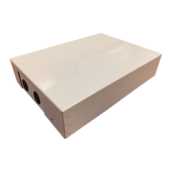
Fig. 1 - 24V Interface
Read and become familiar with these instructions before beginning
the installation.
TABLE OF CONTENTS
SAFETY CONSIDERATIONS.....................................................................1
INTRODUCTION .........................................................................................2
ACCESSORIES.............................................................................................2
DIMENSIONS...............................................................................................3
CLEARANCES .............................................................................................3
INSTALLATION ..........................................................................................4
SYSTEM CONFIGURATION SCENARIOS...............................................4
38MHR) WITH APPROVED DUCTLESS INDOOR UNITS .....................5
SCENARIO 2: SINGLE ZONE OUTDOOR UNITS (38MBR) WITH
APPROVED DUCTLESS INDOOR UNITS................................................6
APPROVED DUCTLESS INDOOR UNITS................................................7
APPROVED RESIDENTIAL 24V FAN COILS FV4..................................9
WIRING.........................................................................................................11
DIP SWITCHES CONFIGURATION ..........................................................12
ERROR CODES ............................................................................................13
WIRING DIAGRAM ....................................................................................14
APPENDIX 1 - COMPATIBILITY AND FAN SPEED WIRING ..............15
APPENDIX 2 - PIPING ADAPTER BUSHINGS/REDUCERS ..................16
APPENDIX 3 - FV4C TRANSFORMER .....................................................16
CONVENTIONAL FAN COILS ..................................................................16
APPENDIX 5 - FV4C AIRFLOW DELIVERY ...........................................16
for Ductless Systems and Hybrid Solutions
Installation Instructions
PAGE
Specifications subject to change without notice.
SAFETY CONSIDERATIONS
Read these instructions thoroughly and follow all warnings or
cautions included in the literature and attached to the unit. Consult the
local building codes and National Electrical Code (NEC) for special
requirements. Recognize safety information.
This is the safety-alert symbol
and in instructions or manuals, be alert to the potential for personal injury.
Understand these signal words: DANGER, WARNING, and CAUTION.
These words are used with the safety-alert symbol.
DANGER identifies the most serious hazards which may result in
severe personal injury or death. WARNING signifies hazards which
could also result in personal injury or death. CAUTION is used to
identify unsafe practices which may result in minor personal injury or
product and property damage. NOTE is used to highlight suggestions
which result in enhanced installation, reliability, or operation.
WARNING
ELECTRICAL SHOCK HAZARD
Failure to follow this warning could result in personal injury or death.
Before beginning any modification or installation of this kit, ensure the
main electrical disconnect is in the OFF position.
Ensure the power is not connected to the fan coil unit. On some systems, both the
fan coil and the outdoor unit may be on the same disconnect. Tag the disconnect
switch with a suitable warning label. There may be more than one disconnect.
CAUTION
EQUIPMENT DAMAGE HAZARD
Failure to follow this warning may result in equipment damage.
DO NOT install the wired controller in an area subjected to excessive steam, oil or
sulfide gas. Doing so may cause the controller to deform and/or fail.
CAUTION
INSTALLATION
Entrust a licensed contractor to install the unit. Installation by unskilled
persons may lead to improper installation, electric shock, or fire.
Reinstallation must be performed by authorized professionals. Non-
compliance may lead to electric shock or fire.
NOTES: Images are for illustration purposes only. Actual models
may differ slightly.
24V Interface Kit
. When you see this symbol on the unit
Advertisement
Table of Contents

Related Manuals for Carrier KSAIC0301230


Summary of Contents for Carrier KSAIC0301230
-
Page 1: Table Of Contents
KSAIC0301230 24V Interface Kit for Ductless Systems and Hybrid Solutions Installation Instructions SAFETY CONSIDERATIONS Read these instructions thoroughly and follow all warnings or cautions included in the literature and attached to the unit. Consult the local building codes and National Electrical Code (NEC) for special requirements. -
Page 2: Introduction
INTRODUCTION ACCESSORIES The 24V Interface provides further flexibility, functionality and The system is shipped with the following accessories (see Table 1). control allowing a single zone or a multi-zone ductless system to be Use all of the installation parts and accessories to install the system. controlled by any 3rd party single-stage conventional thermostat* Improper installation may result in, electrical shock and fire, or cause keeping the Inverter compressor operating as a variable-speed system,... -
Page 3: Dimensions
DIMENSIONS 1.3” 8.7” (32mm) (220mm) 0.6” (15mm) 7.8” 6.9” (200mm) (176mm) 11.1” (283mm) 2.5” (63mm) Fig. 2 — 24V Interface Structure Size CLEARANCES Table 3 — 24V Interface Clearance Dimensions Clearances Unit Minimum Value In (mm) Sides 5.9 (150) Front 24 (610)* Top and Bottom 3 (76.2) -
Page 4: Installation
INSTALLATION Installation Location Back plate The 24V INTERFACE KIT is rated for outdoor and indoor mounting (depending on the application). It is recommended that the kit installation be as close as possible to the indoor unit and the Screws (M4×20) thermostat. -
Page 5: Scenario 1: Single Zone Outdoor Units (38Mpra, 38Ma*R, 38Mhr) With Approved Ductless Indoor Units
SCENARIO 1: SINGLE ZONE OUTDOOR NOTES: Follow the indoor and outdoor unit's general installation instructions. UNITS (38MPRA, 38MA*R, 38MHR) WITH *For the Ducted units, in order to initially setup the static pressure, the APPROVED DUCTLESS INDOOR UNITS 24V interface must be bridged. Temporarily connect the communication wires L1, L2, S and G from the indoor to the outdoor unit until the static pressure settings are complete (refer to the •... -
Page 6: Approved Ductless Indoor Units
SCENARIO 2: SINGLE ZONE OUTDOOR NOTES: Follow the indoor and outdoor unit's general installation instructions. UNITS (38MBR) WITH APPROVED *For Ducted units, in order to initially setup the static pressure, the DUCTLESS INDOOR UNITS 24V interface must be bridged. Temporarily connect the communication wires, S1 and S2, from the indoor unit to the outdoor unit until the static pressure settings are complete (see the Ducted •... -
Page 7: Scenario 3: Multi-Zone Outdoor Units (38Mgr) With Approved Ductless Indoor Units
SCENARIO 3: MULTI-ZONE OUTDOOR NOTES: A set one 24V interface and one thermostat is required per indoor unit UNITS (38MGR) WITH APPROVED head. It is not required to use the 24V interface on every single indoor unit head in the system. Follow the indoor and outdoor unit's general DUCTLESS INDOOR UNITS installation instructions. -
Page 8: Scenario 4: Single Zone Outdoor Unit 38Ma*R With Approved Multi-Family 24V Fan Coils Fma/Fmc/Fmu
SCENARIO 4: SINGLE ZONE OUTDOOR NOTES: Follow the indoor and outdoor unit's general installation instructions. UNIT 38MA*R WITH APPROVED MULTI- The T1 (Return air temperature) sensor should be near or on the unit FAMILY 24V FAN COILS FMA/FMC/FMU on the air inlet side. The thermistor should be installed pointing down into the duct between 2.5ft. -
Page 9: Scenario 5: Single Zone Outdoor Unit 38Ma*R With Approved Residential 24V Fan Coils Fv4
SCENARIO 5: SINGLE ZONE OUTDOOR 9. Configure the dip switches on the 24V Interface for proper operation: UNIT 38MA*R WITH APPROVED For Heat Pump – all switches OFF except SW1-1 = ON RESIDENTIAL 24V FAN COILS FV4 For Cooling Only – all switches OFF except SW1-1 = ON and SW2-1 = ON. - Page 10 TXV REPLACEMENT PROCESS FOR 4. Remove the tail bulb from the suction line by cutting the stainless steel band. PIPING ADAPTER FOR FV4CNF002L00 AND 5. Assemble the line set to the piping adapter kit (40MD000003). FV4CN(B,F)003L Obtain through RCD. a. Refer to “APPENDIX 2 - PIPING ADAPTER BUSHINGS/ REDUCERS”...
-
Page 11: Wiring
WIRING All wires must be sized per NEC (National Electrical Code) or CEC (Canadian Electrical Code) and local codes. Use the Electrical Data table MCA (minimum circuit amps) and MOCP (maximum over current protection) to correctly size the wires and the disconnect fuse or breakers respectively. -
Page 12: Dip Switches Configuration
DIP SWITCHES CONFIGURATION DIP Switch 2-1 Use for selection of the system: Cooling Only or Heat Pump. The 24V INTERFACE KIT must be configured to operate properly with the system components with which it is installed. To successfully Table 10 — DIP Switch 2-1 configure the system, adjust the DIP Switches to match the SW2-1 Result... -
Page 13: Error Codes
ERROR CODES For ease of service, the 24V Interface is equipped with a diagnostic code display LED on the control board (ensure the 24V interface is installed with the directional arrow pointing up to successfully read the error code). Refer to the indoor or outdoor unit’s service manual as listed in Table 16 for a troubleshooting breakdown. -
Page 14: Wiring Diagram
WIRING DIAGRAM Dry Mode NOTE: If the SW4-1 is ON, the SW4-2 takes effect, otherwise the SW1-2 takes effect. BUS BAR Fan Low/Medium/High Fig. 21 — Wiring Diagram GLOSSARY: • Remote Control (CN14): This input may be used to turn the indoor unit on and off remotely by switch or dry contact. If not used, the terminals must have a jumper in place for the unit to operate. -
Page 15: Appendix 1 - Compatibility And Fan Speed Wiring
Number Speed Tap Number FMA4X1800AL 38MAQB12R--3 Tap 1 FMA4X1800AL 38MAQB18R--3 Tap 2 FMA4 Vertical 208/230-1 KSAIC0301230 FMA4X2400AL 38MAQB24R--3 Tap 5 Fan Coil FMA4X3000AL 38MAQB30R--3 Tap 2 FMA4X3000AL 38MAQB36R--3 Tap 4 Table 18 — Compatibility with FMC4 Cased Horizontal Fan Coils... -
Page 16: Appendix 2 - Piping Adapter Bushings/Reducers
APPENDIX 2 PIPING ADAPTER BUSHINGS/REDUCERS Model Size Bushings/Reducers Required (Field Supplied) 3/4” - 1/2” Suction only 12-18 3/8” - 1/4” Liquid 3/4” - 5/8” Suction only 24-36 3/8” - 1/4” Liquid 12-18 3/8” - 1/4” Liquid and 3/4” - 1/2” Suction 24-36 3/4”...
Need help?
Do you have a question about the KSAIC0301230 and is the answer not in the manual?
Questions and answers