Riello RS Series Installation And User Manual
On grid solar pv inverter
Hide thumbs
Also See for RS Series:
- User manual ,
- Installation, use and maintenance instructions (72 pages) ,
- Installation and user manual (47 pages)
Table of Contents
Advertisement
Advertisement
Table of Contents

Related Manuals for Riello RS Series


Summary of Contents for Riello RS Series
- Page 3 Thank you so much for choosing RS 6.0 T - 10.0 T - 15.0 T, the latest generation of grid-tied PV string inverters (hereinafter referred to as the “inverter”) designed and developed by Riello Solartech. Our company is specialised in the development and production of photovoltaic inverters. The solar inverters in this series are high- quality products, carefully designed and constructed with the aim of ensuring high performance.
- Page 4 Check the relevant safety and performance of the inverter; rectify any faults which may compromise the safe operation of the inverter before restarting it. Additional Information To avoid any other unforeseeable risk, contact Riello immediately if any safety issue emerges during operation. NOTICE - 2 -...
- Page 5 ROTECTING THE ENVIRONMENT Our company has devoted extensive resources to the analysis of environmental aspects in the development of our products. All our products pursue the objectives set out in the environmental management system policy, developed by our company in accordance with current legislation.
-
Page 6: Table Of Contents
ONTENTS PRESENTATION _________________________________________________________________________ 5 Product presentation _________________________________________________________________________ 5 INSTALLATION _________________________________________________________________________ 9 Preliminary checks ___________________________________________________________________________ 9 Electrical installation _________________________________________________________________________ 17 USE _________________________________________________________________________________ 26 System Operation ___________________________________________________________________________ 26 User Interface ______________________________________________________________________________ 28 Maintenance _______________________________________________________________________________ 31 Troubleshooting ____________________________________________________________________________ 32 Storage ____________________________________________________________________________________ 34 Disposing of the product ______________________________________________________________________ 34 APPENDIX ____________________________________________________________________________ 35 Technical Specifications ______________________________________________________________________ 35 - 4 -... -
Page 7: Presentation
PRESENTATION RODUCT PRESENTATION This chapter introduces the inverter and describes its functional model, network application, appearance, dimensions and working process, etc. Functional Model Function This series consists of a three-phase grid-tied PV string inverter (transformerless) which converts the DC power generated by PV strings into AC power and feeds the power into the power grid. - Page 8 Outline and Dimensions Front view Side view Bottom view Connections Area (1) DC isolation breaker (2) PV string connectors (3) Wi-Fi antenna connector (4) Communications interface 1 (COM1) (5) Communications interface 2 (COM2) (6) AC output connection (7) Vent valve (8) External protection ground connector - 6 -...
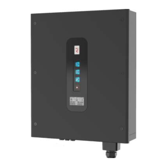
- Page 9 Indicator Panel View LED and LCD Area (1) PV indicator (2) Grid indicator (3) COM indicator (4) Warning indicator (5) LCD - 7 -...
- Page 10 Working Process Basic principle description RS 6.0 T / 10.0 T receive inputs from 2 strings of PV panels. RS 15.0 T receive inputs from 3 strings of PV panels, with the 2nd and 3rd routes terminals merging into one independent MPPT. Then, the inputs are grouped into two independent MPPT routes inside the inverter to track the maximum power point of the PV panels.
-
Page 11: Installation
INSTALLATION RELIMINARY CHECKS Do not install the inverter on flammable building materials or in an area where flammable or explosive DANGER materials are stored. Do not install the inverter in a place where personnel are likely to come into contact with its enclosure and CAUTION heat sinks, to avoid electrical shock or burns. - Page 12 Moving the inverter After checking the outer packaging, move the PV inverter to the designated installation position horizontally. Grip the handles on both sides of the inverter, as shown in the figure below. The inverter is relatively heavy! To prevent device damage and personal injury, arrange two people to move the CAUTION inverter and handle with care.
- Page 13 Disposal If the inverter service life has expired, dispose of the device in accordance with local rules for disposal of electrical equipment waste. Do not dispose of PV inverter with household waste. TÜV Certification The PV inverter is compliant with the TÜV requirements. Installation Requirements These apply to wall-mounted installation, as described below in detail.
- Page 14 Installation Space Requirements • It is recommended that the inverter be installed at eye level to facilitate operation and maintenance. • Reserve enough clearance around the inverter to ensure sufficient space for installation and heat dissipation, as shown in the figure below. Front view Side view (UoM: mm)
- Page 15 Installation in triangle pattern (UoM: mm) Installation in stacked mode (UoM: mm) The clearance between multiple inverters must be increased to ensure proper heat dissipation when they are NOTICE installed in a hot area. - 13 -...
- Page 16 Installation Mode Requirements Install the inverter upright or with a maximum backward tilt angle of 15 degrees to facilitate heat dissipation. Below are some correct/wrong installation modes. The correct installation mode Upright Backward tilt The wrong installation mode Upside-down Horizontal Incorrect installation will lead to failure of the inverter operation.
- Page 17 Step 3 Level the hole positions using a level and mark the hole positions using a marker. (UoM: mm) Step 4 Drill holes using a hammer drill and install expansion bolts, as shown in the figure below. Before drilling the hole in the wall, ensure that no electrical wiring and/or water piping inside the wall will be DANGER damaged.
- Page 18 Installing the Inverter Follow the procedures described below: Step 1 The installer must hold the handle at both sides of the inverter and then lift the inverter and place it standing. Step 2 Mount the inverter on the rear panel and keep the two parts aligned with each another. Step 3 Tighten the M6 hexagon screw at the right side of the inverter to a torque of 3 Nm.
-
Page 19: Electrical Installation
LECTRICAL INSTALLATION Preliminary operations It is advisable to install a circuit breaker on the AC side (see “Recommended circuit breaker” in the technical specifications • table). • Turn the DC switch to off. • Open the AC switch downstream of the inverter. Before performing any electrical connections, ensure that both the DC and AC switches are OFF. - Page 20 Step 3 Remove the ground screws from the ground point. Step 4 Secure the PGND cable (done with steps 1 and 2) using the ground screw and tighten the screw to a torque of 1.2 Nm using a socket wrench. Connecting the AC Output Cables Preparation The AC power cable and AC terminals have to be prepared.
- Page 21 Procedure for Connecting AC Cables Step 1 Remove an appropriate length of the jacket and insulation layer from the AC output cable using a wire stripper, as shown in figure below. Step 2 Insert the exposed core wires into the crimp area of the supplied insulated end sleeve terminals, crimp them using specific tools.
- Page 22 Step 5 Fasten the AC waterproof cover by four hexagon screws supplied; tighten the screws to a torque of 0.8Nm. Step 6 Use a torque wrench to tighten cable gland with 5Nm. Connecting the PV Strings The PV strings connection must comply with the following prerequisites; otherwise, an electric shock may DANGER occur.
- Page 23 Connectors for PV strings: positive and negative DC input connectors are used, as shown below. Positive connector components Negative connector components Procedures for connecting the PV strings Step 1 Remove an appropriate length of the insulation layer from the positive and negative power cables using a wire stripper, as shown in the figure below.
- Page 24 Fasten the Wi-Fi antenna (included in the box) to the inverter, screwing it onto the relative connector. Communication Port 1 (COM1) The COM1 port consist of a DB9 connector and allows to connect any optional accessories. For more information about the available accessories please, visit the https://riello-solartech.it website. - 22 -...
- Page 25 Communication Port 2 (COM2) The COM2 port includes the following features: Remote off contact and External signal contact The Remote off and External signal contacts must be connected and used if required by the local regulation. Connecting Remote off and External signal cables If the local regulation requires the Remote off and External signals please, follow the instructions below.
- Page 26 For more information please, refer to the https://riello-solartech.it/ website. RS485 communication mode for single inverter:...
- Page 27 Step 5 Connect the 6pin Signal terminal to its female terminal of the inverter’s COM2 and fasten the COM2 waterproof cover using the screws removed before. Tighten the waterproof cover screws to a torque of 0.8Nm as well as the locking caps. To prevent corrosion, apply silica gel or fireproof mud to the terminal or interface after NOTE connecting external PGND cables, AC cables, RS485 port.
-
Page 28: Use
YSTEM PERATION Powering the Inverter On Step 1: Switch on the AC circuit breaker. Step 2: Turn on the DC switch on the inverter. Step 3: Observe the statuses of the LED indicator lights and the LCD display on the inverter by referring to the table in the user interface chapter. - Page 29 After that Autotest is executed is possible download the result pressing the relative button in the bottom of the page. For Android devices, a file called Autotest(date).csv will be saved in the root of the mobile phone. For Apple devices it is possible to share the report via e-mail.
-
Page 30: User Interface
NTERFACE The indicator panel of the inverter is composed of LED indicators and a LCD. The LED indicators include the PV, Grid, COM and Warning indicators. LED status LED indicator Status Description Voltage of PV strings meet the conditions for feed-in operation. PV Indicator blink Voltage of PV strings does not meet the conditions for feed-in operation. - Page 31 2) Notice/Alarm When a warning is present on the inverter, the icon will be ON with the specific warning code: the first bit of the code could be (C), it stands for warning type, and the second bit is warning code, please refer to warning code in “LED/LCD (A)/ (b)/ Status and Warning Code Table”.
- Page 32 Grid over-voltage Grid under-voltage Grid over-frequency Grid under-frequency Grid unbalanced PV over-voltage PV under-voltage PV strings abnormal Inverter over-temperature Fan lock Abnormal insulation resistance Abnormal leakage current Strings reverse Control power low Output DC over-current Inverter relay abnormal Abnormal leakage current HCT System fault BUS voltage imbalance BUS over-voltage...
-
Page 33: Maintenance
AINTENANCE Before commissioning or performing maintenance on the inverter and its peripheral distribution unit, switch WARNING off all the charged terminals of the inverter and wait at least 10 minutes after the inverter is powered off. Routine Maintenance Maintenance Check item Check content Maintain content interval... -
Page 34: Troubleshooting
ROUBLESHOOTING When the inverter has an anomaly, its basic common warning and fault handling methods are shown in the following table. Alarm Alarm name Alarm explanation code Grid AC over- The grid voltage exceeds the 1. If the alarm occurs occasionally, it means that the grid is voltage allowed range. - Page 35 1. If the alarm occurs occasionally, this is due to temporary abnormal grid voltage and the inverter can automatically recover Inverter relay its normal operating status, so no action is needed. The output relay cannot be closed. abnormal 2. If the alarm occurs repeatedly or lasts a long time, check if the output neutral and live lines are inversely connected.
-
Page 36: Storage
Removing the Inverter Perform the following procedures to remove the inverter: Step 1: Turn off the inverter (see dedicated chapter). Step 2: Disconnect all cables from the inverter, including any communication cables, DC input and AC output power cables, and PGND cables, as shown in the following figure. -
Page 37: Appendix
APPENDIX ECHNICAL PECIFICATIONS Model RS 6.0 T RS 10.0 T RS 15.0 T Efficiency Max efficiency 97.9% European efficiency 97.3% 97.4% 97.5% Input (PV) Max input voltage 1000 V Rated input voltage 620 V Max input current 22A (11A/11A) 33A (11A/22A) Max short-circuit current 30A (15A/15A) 45A (15A/30A) - Page 38 HMI & COM Display Wireless & APP + LED, LCD Communication Wi-Fi (integrated), RS485 (integrated) Certification Safety IEC62109-1, IEC62109-2 EN 61000-6-1, EN 61000-6-2, EN 61000-6-3, EN 61000-6-4 Grid code CEI 0-16, CEI 0-21, RD1699 Warranty 5 Years / 10 Years (optional) Notes: * The grid power voltage range can be set according to national voltage standards.
- Page 39 0MNPS36K0RUENUA...
Need help?
Do you have a question about the RS Series and is the answer not in the manual?
Questions and answers
Hi, Since 5-4 our Riello inverter is not working correct; normally it shows the energy that we consume on the inverter ; now it show the energy produced, but it is not coming to our house? It looks like it is going to the grid?
The Riello RS Series inverter is a grid-tied PV string inverter designed to convert solar energy into AC power and feed it into the power grid. It displays energy produced because its purpose is to measure and report the amount of solar energy generated by the PV system. It may send energy to the grid instead of the house if:
1. The inverter is configured for grid feed-in, which is its intended design.
2. The house is not consuming all the generated power, so the excess is sent to the grid.
3. There may be no energy management system prioritizing house consumption before grid export.
This behavior is normal for grid-tied inverters.
This answer is automatically generated