Riello RS Series Installation And User Manual
Hide thumbs
Also See for RS Series:
- User manual ,
- Installation, use and maintenance instructions (72 pages) ,
- Installation and user manual (39 pages)
Table of Contents
Advertisement
Quick Links
Advertisement
Table of Contents

Subscribe to Our Youtube Channel
Related Manuals for Riello RS Series


Summary of Contents for Riello RS Series
- Page 3 Note: this user manual is subject to change (specific please in kind prevail) without prior notice. The latest version of the user manual and additional information on the product are available on http://www.riello-solartech.com, and/or by consulting your dealer. Symbol Conventions...
- Page 4 Check the relevant safety and performance of the inverter; rectify any faults which may compromise the safe operation of the inverter before restarting the latter. Additional Information To avoid any other unforeseeable risk, contact Riello immediately if any safety issue emerges during operation. NOTICE - 2 -...
- Page 5 ROTECTING THE ENVIRONMENT Our company has devoted extensive resources to the analysis of environmental aspects in the development of our products. All our products pursue the objectives set out in the environmental management system policy, developed by our company in accordance with current legislation.
-
Page 6: Table Of Contents
ONTENTS PRESENTATION _________________________________________________________________________ 5 Product presentation _________________________________________________________________________ 5 INSTALLATION _________________________________________________________________________ 9 Preliminary checks ___________________________________________________________________________ 9 Electrical installation _________________________________________________________________________ 17 USE _________________________________________________________________________________ 23 System Operation ___________________________________________________________________________ 23 User Interface ______________________________________________________________________________ 23 Maintenance _______________________________________________________________________________ 25 Troubleshooting ____________________________________________________________________________ 26 Storage ____________________________________________________________________________________ 28 Disposal of the inverter _______________________________________________________________________ 28 CONFIGURATION &... -
Page 7: Presentation
PRESENTATION RODUCT PRESENTATION This chapter introduces the inverter and describes its functional model, network application, appearance, dimensions and working process, etc. Functional Model Function This series consists of a single-phase grid-tied PV string inverter (transformerless) which converts the DC power generated by PV strings into AC power and feeds the power into the power grid. - Page 8 Outline and Dimensions RS 1.5-2.0 3.0 PV inverter with single MPPT input (UoM: mm) RS 4.0/5.0/6.0 PV inverter with double MPPT input (UoM: mm) Bottom view RS 1.5/2.0/3.0 Bottom view RS 4.0/5.0/6.0 - 6 -...
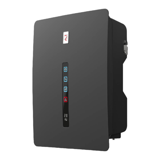
- Page 9 Connections Area (1) Vent valve (2) DC isolation breaker (3) PV string terminal (4) AC output connector (5) Communications interface (6) External protection ground interface Indicator Panel View LED and LCD Area (1) PV indicator (2) Grid indicator (3) COM indicator (4) Warning indicator (5) LCD - 7 -...
- Page 10 Working Process Basic principle description The RS 1.5/2.0/3.0 PV inverters with single MPPT input receives inputs from only one string of PV panels. The RS 4.0/5.0/6.0 PV inverters with double MPPT input receive inputs from two strings of PV panels. Then the inputs are grouped into one or two independent MPPT routes inside the inverter to track the maximum power point of the PV panels.
-
Page 11: Installation
INSTALLATION RELIMINARY CHECKS Do not install the inverter on flammable building materials or in an area where flammable or explosive DANGER materials are stored. Do not install the inverter in a place where personnel are likely to come into contact with its enclosure and CAUTION heat sinks, to avoid electrical shock or burns. - Page 12 Moving the inverter After checking the outer packaging, move the PV inverter to the designated installation position horizontally. Grip the handles on both sides of the inverter, as shown in the figure below. Do not place the PV inverter with its wiring terminals in contact with the floor, because the power ports and signal ports at the bottom of the device are not designed to bear the weight of the inverter.
- Page 13 Installation Requirements These apply to wall-mounted installation, as described below in detail. Determining the Installation Position Basic Requirements • The inverter is protected to IP65 and can be installed indoors or outdoors. • The installation method and position must be appropriate for the weight and dimensions of the inverter. •...
- Page 14 Installation Space Requirements • It is recommended that the inverter be installed at eye level to facilitate operation and maintenance. • Reserve enough clearance around the inverter to ensure sufficient space for installation and heat dissipation, as shown in the figure below. Front view Side view When installing multiple inverters, install them along the same line if sufficient space is available, or in a triangle pattern or stacked if...
- Page 15 Installation in triangle pattern (UoM: mm) 10 00 Installation in stacked mode (UoM: mm) The clearance between multiple inverters must be increased to ensure proper heat dissipation when they are NOTICE installed in a hot area. - 13 -...
- Page 16 Installation Mode Requirements Install the inverter upright or with a maximum backward tilt angle of 15 degrees to facilitate heat dissipation. Below are some correct/wrong installation modes. The correct installation mode Upright Backward tilt The wrong installation mode Upside-down Horizontal Incorrect installation will lead to failure of the inverter operation.
- Page 17 Step 3 Level the hole positions using a level and mark the hole positions using a marker. level Step 4 Drill holes using a hammer drill and install expansion bolts, as shown in the figure below. Before drilling the hole in the wall, ensure that no electrical wiring and/or water piping inside the wall will be DANGER damaged.
- Page 18 Installing the Inverter Follow the procedures described below: Step 1 The installer must hold the handle at both sides of the inverter and then lift the inverter and place it standing. Step 2 Mount the inverter on the rear panel and keep the two parts aligned with one another. Step 3 Tighten the two hexagon screws at both sides of the inverter to a torque of 1.2 Nm and 3 Nm respectively.
-
Page 19: Electrical Installation
LECTRICAL INSTALLATION Preliminary operations • It is advisable to install a circuit breaker on the AC side (see “Recommended circuit breaker” in the technical specifications table). • Turn the DC switch to off. • Open the AC switch downstream of the inverter. Before performing any electrical connections, ensure that both the DC and AC switches are OFF. - Page 20 Step 3 Remove the ground screws from the ground points. Step 4 Secure the PGND cable (done with steps 1 and 2) using the ground screw and tighten the screw to a torque of 1.2 Nm using a socket wrench. Connecting the AC Output Cables Preparation The AC power cable and AC terminals have been prepared.
- Page 21 Procedure for Connecting AC Cables Step 1 Remove an appropriate length of the jacket and insulation layer from the AC output cable using a wire stripper, as shown in figure below. 8 ~1 5 3 6 ~4 0 Step 2 Insert the exposed core wires through the nut of the AC terminal sleeve in the middle, with the L terminal for the line wire, the N terminal for the neutral wire and the G terminal for the earth wire, then tighten the screw.
- Page 22 Connecting the PV Strings The PV strings connection must comply with the following prerequisites; otherwise, an electric shock may DANGER occur. PV modules generate electrical energy when exposed to sunlight and can create an electric shock hazard. Therefore, when connecting the PV modules, shield them with opaque cloth. Before connecting the DC input power cables, ensure that the voltage on the DC side is within the safe range and that the DC SWITCH on the inverter is OFF.
- Page 23 Procedures for connecting the PV strings Step 1 Remove an appropriate length of the insulation layer from the positive and negative power cables using a wire stripper, as shown in the figure below. Po si ti ve me ta l co nn e cto r Ne ga ti ve me ta l co nn e cto r Step 2 Insert the exposed areas of the positive and negative power cables into the metal terminals of the positive and negative connectors respectively and crimp them using a crimping tool, as shown below.
- Page 24 A module is available including the RS485 standard, besides contacts and power limiter functions. This module must be installed to the inverter communication interface. For more details refer to www.riello-solartech.com. Installation Verification Once the inverted has been installed, check the following items: •...
-
Page 25: Use
YSTEM PERATION Powering the Inverter On Step 1: Switch on the AC circuit breaker. Step 2: Turn on the DC switch on the inverter. Step 3: Observe the statuses of the LED indicator lights on the inverter by referring to the table in the user interface chapter. When the LED status lights show that the inverter has entered the grid connection mode, it means that the inverter is operating properly. - Page 26 LED/LCD Status and Warning Code Table Grid Warning Display Indicator Indicator Indicator Indicator Normal status (with Wi-Fi Internet Instantaneous connection OK) power generated Starting up (inverter tries to connect 0.0 kW to grid) Wi-Fi connection Router OK – Internet Fail Wi-Fi connection Router OK –...
-
Page 27: Maintenance
AINTENANCE Before performing maintenance on and commissioning the inverter and its peripheral distribution unit, switch off all the charged terminals of the inverter and wait at least 10 minutes after the inverter is powered WARNING off. Routine Maintenance Maintenance Check item Check content Maintain content interval... -
Page 28: Troubleshooting
ROUBLESHOOTING When the inverter has an exception, its basic common warning and exception handling methods are shown in the following table. Alarm Alarm name Alarm explanation code Grid AC over- The grid voltage exceeds the 1. If the alarm occurs occasionally, it means that the grid is voltage allowed range. - Page 29 1. If the alarm occurs occasionally, this is due to temporary abnormal grid voltage and the inverter can automatically recover Inverter relay The output relay cannot be its normal operating status, so no action is needed. abnormal closed. 2. If the alarm occurs repeatedly or lasts a long time, check if the output neutral and live lines are inversely connected.
-
Page 30: Storage
Removing the Inverter Perform the following procedures to remove the inverter: Step 1: Turn off the inverter (see dedicated chapter). Step 2: Disconnect all cables from the inverter, including any communication cables, DC input and AC output power cables, and PGND cables, as shown in the following figure. -
Page 31: Configuration & Monitoring
The second Wi-Fi channel allows the connection with the own home router for sending information to the Riello Solartech cloud that will be visualised on the “RS Monitoring” supervision web portal. - Page 32 Start the RS Connect app and select "Connect Inverter" The following screen will appear; select the inverter from the list. NOTE: for some devices, it is necessary to enable the position function. Select the inverter by clicking on the serial number. At this point, the MAIN screen will appear.
- Page 33 From the Main page the following menus can be accessed: History / Production / Maintenance / Settings / Autotest/ Power Limiter History This page shows the list of last 128 events and alarms that have occurred. Production This page shows the daily / monthly / yearly energy production graphs. - 31 -...
- Page 34 Maintenance This menu is reserved for technical service personnel. Not available for standard users. Settings This menu is used to set: Date and time Wi-Fi connection with own router RS484 connection configuration Advanced settings are reserved for technical service personnel. Not available for standard users. Autotest This menu allows for easily starting the AUTOTEST process by simply pressing on START button.
- Page 35 Cloud Connection via App To use this feature, you must first create an account and register your own solar plant on the Riello Solartech cloud portal at www.riello-rsmonitoring.com. Start the RS Connect app and login with the account name and password (the same ones used to register with the Riello Solartech cloud portal).
-
Page 36: Rs Monitoring" Cloud Portal
The processing of this data, in addition to weather and environmental data, allows for keeping the systems totally under control. By registering at the web portal www.riello-rsmonitoring.com.it. it is possible to monitor the production and consumption trends of one or more photovoltaic systems by logging in with a single account. Furthermore, it is possible to activate the reception of fault alarm messages and those related to production. - Page 37 Access to the RS Monitoring portal To access the RS Monitoring portal after initial registration, a user will need to connect to the URL riello-rsmonitoring.com, and log in by entering their Username and Password (see Figure 1). If the user is not yet registered, they will need to do so by clicking on the “Sign Up!” link at the bottom of the page.
- Page 38 All users must register by entering the following information: Username (Account User Name, represented by their email address) Password (Account User Password) Full Name (e.g. Name and Surname) Default language Authorisation for data processing (Privacy) After registration, the user will receive a confirmation email containing their Username and Password for access to the RS Monitoring portal.
- Page 39 Add Plant In the Add Plant section, a user can create their own plant or acquire one created by another user (e.g. their installer). Create Plant The Create Plant screen allows a user to initialise their field. The user must: •...
- Page 40 • Dashboard With the Smart Dashboard, customers and maintenance staff of a particular photovoltaic plant will have access in real time, and at all times, to information relating to the nominal power on the DC and AC sides; the daily, weekly, monthly, yearly and total energy, and also the status of the devices (when necessary, there will be a notice next to each alarm icon).
- Page 41 • Data The Data section allows the user to display all the information regarding their plant on a field or single inverter level. Figure 5: Data Section Plant data This page allows the user to display the information on a plant level, showing in real time the power or energy of the plant (calculated as the sum of the powers/energies of the inverters associated with it) for the current day;...
- Page 42 History The History log section will provide the customer with information regarding the exact moment when an IN or OUT alarm is triggered for the inverters of the plant; by selecting a specific time period, one can view the information on the screen (by clicking on Load Log) or download an excel file which contains this data (by clicking on Download Events Log).
- Page 43 Service Alert and Management of Alarms The RS Monitoring system is equipped with an ALERT Service, which is detailed and configurable, so that users can be informed at all times via email about any errors or malfunctions of the plant. The management of alarms is divided into the following groups: GROUP 1 - Absence of communication: This error is generated when packages are not sent by an inverter for more than 8 hours.
-
Page 44: Appendix
APPENDIX ECHNICAL PECIFICATIONS Model RS 1.5 RS 2.0 RS 3.0 RS 4.0 RS 5.0 RS 6.0 Efficiency 97.4% Max efficiency 97.6% 97.6% 97.5% 97.4% 97.4% 96.8% European efficiency 96.1% 96.6% 96.8% 96.9% 97.1% Input (PV) 600 V Max input voltage 360 V Rated input voltage 22 A (2x11 A) - Page 45 HMI & COM Wireless & app + LED, LCD Display Wi-Fi (integrated), RS485 (optional) Communication Certification IEC62109-1, IEC62109-2 Safety EN 61000-6-1, EN 61000-6-2, EN 61000-6-3, EN 61000-6-4 CEI 0-21, RD1699 Grid code 5 Years/10 Years (optional) Warranty Notes: * The grid power voltage range can be set according to national voltage standards. ** The power grid frequency range can be set according to national grid standards.
- Page 47 0MNPS11K5RUENUB...
Need help?
Do you have a question about the RS Series and is the answer not in the manual?
Questions and answers