Table of Contents
Advertisement
Quick Links
Advertisement
Table of Contents

Related Manuals for Riello RS 3.6 HYBRID


Summary of Contents for Riello RS 3.6 HYBRID
- Page 3 Note: this user manual is subject to change without prior notice. The latest version of the user manual and additional information on the product are available on http://www.riello-solartech.com, and/or by consulting your dealer. Symbol Conventions The safety symbols used in this manual, which highlight potential safety risks and important safety information, are listed below:...
- Page 4 AFETY PRECAUTIONS Personnel Safety • The PV inverter must be installed, electrically connected, operated and maintained by a specially trained technician. • The qualified technician must be familiar with the safety regulations concerning the electrical system, the working process of the PV power generation system and the standards of the local power grid. •...
- Page 5 Disconnect all energy sources before connecting and/or disconnecting the Battery terminals. • Both positive and negative poles must be isolated from earth. Additional Information To avoid any other unforeseeable risk, contact Riello immediately if any safety issue emerges during operation. NOTICE RISK OF VOLTAGE FEEDBACK Before operating on this circuit...
- Page 6 ROTECTING THE ENVIRONMENT This product does not contain hazardous materials such as CFCs, HCFCs or asbestos. Product packaging is made from RECYCLABLE MATERIALS. The disposal of individual components must be performed in accordance with current legislation in the country where the product is used. Refer to the following table for material identification: ESCRIPTION ATERIAL Packaging box...
-
Page 7: Table Of Contents
ONTENTS PRESENTATION _______________________________________________________________________- 6 - Product presentation _______________________________________________________________________ - 6 - INSTALLATION _______________________________________________________________________- 9 - Preliminary checks _________________________________________________________________________ - 9 - Electrical installation _______________________________________________________________________ - 19 - USE ______________________________________________________________________________ - 31 - System operation _________________________________________________________________________ - 31 - User interface ____________________________________________________________________________ - 33 - Working mode ____________________________________________________________________________ - 36 - Using the app _____________________________________________________________________________ - 42 - Maintenance _____________________________________________________________________________ - 52 -... -
Page 8: Presentation
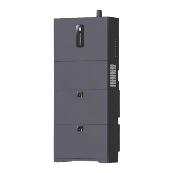
PRESENTATION RODUCT PRESENTATION Our hybrid storage system (ESS - Energy Storage System) is designed to supply energy continuously to the loads connected to it using, depending on the different power supply situations, photovoltaic energy, mains power and/or the energy stored in the dedicated battery modules. - Page 9 Battery configuration and capacity One or more batteries RS BATLIO 5120 can be stacked to expand the capacity. Each battery pack has its own intergated power control module, the system supports a maximum of six battery packs in parallel, with the following capacity. 5.12kWh 10.24kWh 15.36kWh...
- Page 10 Connections area of Inverter DC Switch Battery connections PV Switch PV connectors Backup output connector Ground connection Grid input connector Communication ports Slot for Wi-Fi/Ethernet module connection Connections area of Battery Pack Battery indicators Battery connections side screw ON/OFF Button Battery connectors Communication ports DC Breaker...
-
Page 11: Installation
INSTALLATION RELIMINARY CHECKS Checking the packaging contents • Upon receiving the inverter and/or batteries, check that the packaging materials are intact. • After unpacking, check that the deliverables are complete, intact and consistent with your order list. • Examine the PV inverter, batteries and their fittings for any damage such as scraps and cracks. If any of the damage mentioned above is found, contact the dealer immediately. - Page 12 Packing Assy of battery Battery Mounting brackets (2x) Connection strap for grounding M6 Expansion screws (2x) M4 Security screws (6x) Locating pins (4x) Battery cables (BAT+/BAT-) Link communication cable (BAT to BAT) Packing Assy of RS Hybrid Side Mounting Kit (XES2RS01A, optional) Base support Top cover...
- Page 13 Moving the inverter After checking the outer packaging, move the PV inverter to the designated installation position horizontally, as shown in the figure below. The inverter is relatively heavy! To prevent device damage and personal injury, arrange two people or a CAUTION lifting mechanism to move the inverter and handle with care.
- Page 14 Installation Requirements Basic Requirements • The inverter and batteries are IP66 compliant and can be installed both indoors and outdoors. • The installation site must be inaccessible to unauthorized personnel due to the high heat sink temperature. • Do not install the PV inverter in areas containing highly flammable materials or gases. •...
- Page 15 Installation Base support installation Step 1 Fix the two brackets for the support base on the rear side of the base with 6x M4 security screws supplied (tighten with a torque of 1.2Nm). Install the 4 alignment pins provided on the top side of the base. Step 2 Place the base against the wall.
- Page 16 System installation (typical configuration with 2 batteries and inverter) Step 1 Align the first battery pack with the base support according to the locating pins. After alignment, press down the battery tightly to make sure it fits into place. Step 2 Install four locating pins (supplied with the battery module) on top of the battery. Step 3 Temporarily rest the retaining brackets in their respective positions on the battery module.
- Page 17 Step 5 Install the expansion tubes on the wall. Step 6 Fasten the brackets to the battery with 4x M4 security screws supplied (tighten with a torque of 1.2Nm) and secure the brackets to the wall using the 2 expansion screws supplied (tighten with a torque of 2-2.5Nm). Step 7 Install the following battery pack according to step 1 and 2.
- Page 18 Step 10 Remove the mounting bracket, cover the batteries with the shipping bag to avoid dust contamination and then drill the six holes Ø= 10mm, depth = 60mm in the previously marked positions. Step 11 Install expansion tubes as described in step 5. Secure the wall bracket to the battery with the 2 jam screws. Fasten 6x M6 expansion screws and the M4 security screw to secure the bracket in its position.
- Page 19 Step 13 Install the M4 security screw on the side of inverter (tighten with a torque of 1.2Nm). - 17 -...
- Page 20 Side installation For the side installation of the battery module, the “Side mounting kit” is needed. NOTE Step 1 To install the support base and the battery modules, follow the instructions reported in the previous chapter (steps 1-8), for all the battery modules to be installed (max 4 battery modules on a single tower). Step 2 Place the top cover on the upper battery module as shown in the picture below.
-
Page 21: Electrical Installation
RS 3.6 HYBRID. • It is advisable to install a circuit breaker on the critical load side with rated current higher than 40A for RS 6.0 HYBRID, 32A for RS 3.6 HYBRID. • Turn off the PV switch and battery switch. - Page 22 Connecting Protection Ground (PGND) cables Preparation The ground cable and OT terminals have to be prepared. A protective earth (PE) terminal is equipped at the side of the inverter. Please be sure to connect this PE terminal to the PE bar for reliable grounding. It is recommended to install AWG 10~12 (4~6 mm yellow-green lines as PE cables, in all cases the PE cables must have at least the same cross-section as the AC output cables.
- Page 23 Step 3 Plug the connector’s end terminal into the body being careful to align the arrows until it clicks, then tighten the nut. Grid (RS 6.0 HYBRID) Grid (RS 3.6 HYBRID) Backup (all models) Connection to the inverter Insert the connectors in the corresponding ports until a click is heard.
- Page 24 Connecting the batteries The following image shows the battery connection diagram. Beware of the polarity! The positive and negative cables can be swapped, and reverse polarity will damage the WARNING inverter! When connecting lithium batteries, ensure that all DC switches are off. Never close the DC switches before WARNING connecting all LINK cables and powering up the BMS of every battery.
- Page 25 Connecting the PV strings The PV strings connection must comply with the following prerequisites; otherwise, an electric shock may DANGER occur. PV modules generate electrical energy when exposed to sunlight and can create an electric shock hazard. DANGER Therefore, when connecting the PV modules, shield them with opaque cloth. Before connecting the DC input power cables, ensure that the voltage on the DC side is within the safe range and that the DC SWITCH on the inverters is OFF.
- Page 26 Step 2 Insert the exposed areas of the positive and negative cables into the metal terminals of the positive and negative connectors respectively and crimp them using a crimping tool. Step 3 Insert the crimped positive and negative cables into the corresponding positive and negative connectors. Tighten the waterproof nuts on each connector with an appropriate tool.
- Page 27 Connecting the CT or Energy Meter (optional) The inverter can operate using a Current Transformer (CT, supplied) or an Energy Meter (optional, not supplied), alternatively. Before the connection to the grid, install a separate AC breaker with a current capacity of at least 60A between the grid and the CT/Energy Meter.
- Page 28 Energy Meter Connection The inverter supports the DDSU666 Energy Meter manufactured by CHINT, which is not included in the box. The next figure shows the terminals needed to connect the Energy Meter to the system. The following image shows how the energy meter is to be connected to the system. Connection to the inverter The Energy Meter connects to the inverter using the same RJ45 cable as the Current Transformer (CT).
- Page 29 Connecting the Battery Management System It is mandatory to connect the battery BMS (Battery Management System) to the inverter to properly charge and discharge the battery. The BMS gets connected to a dedicated RJ45 connector, whose pinout is shown below. RJ45 Connection Pinout Signal RS485_A...
- Page 30 Communication interfaces The image below shows the communication interfaces in the communication port on the bottom of the inverter. Interface Description For firmware upgrade PARAL 4-pin interface for multiple inverters operation with switch for terminating resistor. RS485 4-pin interface for RS485 communication RJ45 interface for Demand Response Mode (for Australia applications) CT/METER Interface for Energy Meter or Current Transformer (CT)
- Page 31 Connecting the Wi-Fi Module Step 1 Loosen the two screws that keep the cover installed on top of the inverter. Step 2 Insert the Wi-Fi module into the port. Step 3 Secure the module with 2 M4 screws (included). Installing the cable cover Install the cable cover onto the inverter’s bracket by pushing it into position.
- Page 32 Installation self-check It is mandatory to verify the inverter installation. This is to avoid electric shock, fire risks, other injuries or faults. Once the inverter has been installed, check the following items: • Ensure that the inverter is firmly installed. •...
-
Page 33: Use
YSTEM OPERATION Powering the inverter on The image below shows the start-up procedure for the hybrid inverter system. Step 1 Close the PV switch on the inverter. Step 2 Close the DC switch (batteries) on the inverter. Step 3 Close the DC switch on every battery pack. Step 4 Push the power button on one battery pack for 1~2 seconds. - Page 34 Powering the inverter off The image below shows the power-off procedure for the hybrid inverter system. Step 1 Connect the smartphone App via Bluetooth. Refer to the appropriate section for details. Power off the inverter in the quick setup section. Step 2 Open the backup AC breaker.
-
Page 35: User Interface
SER INTERFACE The indicator panel of the inverter is composed of six LED indicators. The LED indicators include the PV, BAT, GRID, BACKUP, COM and ALARM indicators. Status Description Indicator PV Input is available and normal. Blinking PV Input is available but abnormal. PV Input is unavailable. - Page 36 LED Status and Warning Code Table Alarm name Alarm LED State Code GRID BACKUP ALARM PV abnormal No PV PV over voltage PV under voltage PV irradiation weak PV string reverse PV string abnormal On grid Grid absent Grid over voltage Grid under voltage Grid over frequency Grid under frequency...
- Page 37 Battery pack LED Each battery pack is equipped with 8 LEDs showing the status and charge of the pack itself. Items Normal Alarm Battery Level Indicator Descriptions Status Shutdown All OFF Same as normal Standby According to battery level discharge Normal According to battery level, the highest LED blinks.
-
Page 38: Working Mode
ORKING MODE The inverter supports several different working modes, described below. 1) Self-used mode Under self-used mode, the priority of PV energy will be Load > Battery > Grid, that means the energy produced by PV gives priority to local loads, excess energy is used for charging the battery, and the remaining energy is fed into the grid. This is the default mode to increase self-consumption rate. - Page 39 No PV power When there is no PV power from the strings, the inverter will first discharge the battery energy to power the loads. If the demand is not met, then it will consume power from the grid. 2) Feed-in Priority mode Under feed-in priority mode, the priority of PV energy will be Load >...
- Page 40 Limited PV Energy When PV energy is limited and cannot meet the feed-in grid power, the battery will discharge to meet it. No PV input When there is no PV input, the inverter will first discharge the battery energy for powering the loads. If the demand is not met then the inverter will draw power from the grid.
- Page 41 3) Time-based control mode Under this mode, the user can control the charging and discharging of the inverter. The following parameters can be set: • Charge and discharge frequency: one time or daily • Charging start time: 0 to 24 hours •...
- Page 42 Allow AC charging Wealthy PV power When PV energy is wealthy, PV charges the battery first, then meets the load and if there is any excess energy it will be fed into the grid. Limited PV power When the PV energy is not enough to charge the battery, the grid energy will charge the battery as supplement. Meanwhile, the loads are powered from the grid energy.
- Page 43 5) Off Grid mode Under this mode only critical loads are supplied to ensure that important loads continue to work without power failure. Under this mode, the inverter can’t work without the battery. This mode is automatically enabled when the inverter detects an AC grid malfunction and the EPS output is enabled in the App.
-
Page 44: Using The App
SING THE APP Download the app Step 1 Scan the QR code on the inverter to download the App. Step 2 Download the App from the App Store or Google Play Store. Step 3 Open the App. To ensure proper working of the App and the inverter, grant the access to all permissions by accepting the pop-up windows. - Page 45 Local Setting • Access permission Before using the local setting, the App should access some permissions. You need to grant access to all permissions by clicking allow on every pop-up windows. • Connect inverter Enable Bluetooth on your device, then open the App. Press Local Connection to go to the connect page.
- Page 46 • Quick setup Connect the device to the router that will be used to make the inverter connect to internet. Step 1 Go to Quick Settings page. Step 2 Ensure the Wi-Fi SSID is correct. Step 3 Manually insert the Wi-Fi password. Step 4 Click “start the configuration”.
- Page 47 Set parameters for grid power, in this case the Power control method, Meter location, Power flow direction and maximum feed in grid power. Step 1 Click each item to enter the parameters requested according to installation. Step 2 Click Next. Step 3 If needed, press Previous to go back to the previous page.
- Page 48 • Chart Under this menu, the user can check the relevant data curve of energy (Daily, Monthly and Annual). The App can retain informations for a limited period of time, based on the type of visualization: Daily Data: 7 days Monthly Data: 36 months Yearly Data: 10 years Daily data...
- Page 49 Different colour curves represent different energy data. Click the icon to show and hide the corresponding curve. Click the curves to display a small pop-up showing precise data information. The user can also press the date to choose the day to check, or as an alternative click the left and right arrows near to the date to change the day one by one.
- Page 50 • Local Connection Homepage The Homepage shows basic information about the inverter and alarms, if any. Click to display all active warnings and alarms; if the alarm has been taken care of, the user can also mark the alarm itself as “Inactive”. •...
- Page 51 • Console Access Management Go to Console > Access Management page. In this page the user can change the login credentials and permissions. Communication Setting Go to Console > Communication Setting page. In this page the user can set or change the parameters of communication settings and it is divided in three subpages: Basic Setting, RS485 Setting and Ethernet Setting.
- Page 52 Autotest Go to Console > Autotest page. This menu allows for easily starting the Autotest process by simply pressing on Start button. After that Autotest is executed is possible download the result pressing the dedicated DOWNLOAD button in the bottom of the page*. A file called Autotest(date).csv will be saved in the root of the mobile phone.
- Page 53 Power Limit Go to Console > Power Limit page. In this page the user can set or change the parameters of power limit. Other settings Go to Console > Other setting page. In this page, the user can synchronize the date and time of the inverter with the device.
-
Page 54: Maintenance
AINTENANCE Before commissioning or performing maintenance on the inverter and its peripheral distribution unit, switch WARNING off all the charged terminals of the inverter and wait at least 5 minutes after the inverter is powered off. Routine maintenance Maintenance Check item Check content Maintain content interval... -
Page 55: Troubleshooting
ROUBLESHOOTING The following table shows inverter’s basic common warning and fault handling methods. Alarm Alarm name Alarm explanation Measures recommended code If the alarm occurs occasionally, it means that the grid is operating abnormally; the inverter can automatically restore its normal operating status after the grid returns normal. - Page 56 Alarm Alarm name Alarm explanation Measures recommended code The PV module input Ensure that the maximum voltage of every single string does not exceed PV over voltage is higher than the maximum MPPT voltage. If this is not the case, change the PV string voltage the allowed range.
- Page 57 Alarm Alarm name Alarm explanation Measures recommended code Unbalance If the alarm occurs occasionally, the inverter can automatically recover. DC-link No action is needed. voltage If the alarm occurs repeatedly, contact the customer service centre. If the alarm occurs occasionally, the inverter can automatically recover. DC-link over No action is needed.
- Page 58 Alarm Alarm name Alarm explanation Measures recommended code If the alarm occurs occasionally, the inverter can automatically recover. No action is needed. The battery Battery under If the alarm occurs repeatedly, check whether: temperature exceeds temperature The battery is not mounted exposed to extreme cold weather. the allowable range.
-
Page 59: Storage
Removing the inverter To remove the inverter, follow the steps below. Step 1: Turn off the inverter (see dedicated chapter) Step 2: Remove all cables from the inverter, including any communication cables, PV input, battery cables, AC output power cables and PGND cables, as shown in the following figure. -
Page 60: Disposing Of The Product
ISPOSING OF THE PRODUCT Users take the responsibility for the disposal of the inverter. Dispose the inverter in accordance with relevant local regulations and standards to avoid property losses WARNING or casualties. Some parts of the inverter may cause environmental pollution. Please dispose of them in accordance with NOTICE the disposal regulations for electronic waste applicable at the installation site. -
Page 61: Appendix
APPENDIX ECHNICAL SPECIFICATIONS NVERTER Item Specification Comments Model RS 3.6 HYBRID RS 6.0 HYBRID Inverter Type Hybrid inverter Max. Efficiency (PV to AC) 95.7% 96.6% Max. Efficiency (AC to BAT) 92.3% 92.7% Max. Efficiency (BAT to AC) 92.6% 92.8% Rated Battery Voltage 51.2 Vdc... - Page 62 Item Specification Comments Model RS 3.6 HYBRID RS 6.0 HYBRID Transfer Time 10ms (typ), 20ms (max) THDv < 3% At rated resistive load General -25°C ~ 60°C Up to 40°C without derating Operating Temperature Range -30°C ~ 65°C Storage Temperature Range...
-
Page 63: Battery
ATTERY Item Specification Comments Model RS BATLIO 5120 Battery Type LFP (LiFePO4) Rated Battery Voltage 51.2Vdc Battery Voltage Range 44.8Vdc ~ 58.4Vdc Battery Module Energy 5.12kWh Max. Charge/Discharge Current 100A / 100A Max. No. of Module in Parallel Operating Temperature Range for Charge 0°C ~ 45°C Operating Temperature Range for Discharge -20°C ~ 55°C... - Page 64 0MNES23K6RUENUA...
Need help?
Do you have a question about the RS 3.6 HYBRID and is the answer not in the manual?
Questions and answers