Table of Contents
Advertisement
Quick Links
Advertisement
Table of Contents

Subscribe to Our Youtube Channel
Related Manuals for Sierra Wireless oMG 500


Summary of Contents for Sierra Wireless oMG 500
- Page 1 500 Installation Guide oMG-ED-130507 October 2, 2015...
- Page 2 Data may be delayed, corrupted (i.e., have errors) or be totally lost. Although significant delays or losses of data are rare when wireless devices such as the Sierra Wireless modem are used in a normal manner with a well-constructed network, the Sierra Wireless modem should not be used in situations where failure to transmit or receive data could result in damage of any kind to the user or any other party, including but not limited to personal injury, death, or loss of property.
- Page 3 This product may contain technology developed by or for Sierra Wireless Inc. ® This product may include technology licensed from QUALCOMM This product is manufactured or sold by Sierra Wireless Inc. or its affiliates under one or more patents licensed from InterDigital Group and MMP Portfolio Licensing. Copyright ©...
- Page 4 500 Installation Guide Document History Version Date Updates October 2, 2015 Enhanced LED blink pattern table February 27, 2015 Updated to SWI Template. oMG-ED-130507 Rev 1.2 October 2, 2015...
-
Page 5: Table Of Contents
Contents 1. INTRODUCTION ....................8 1.1. Who Should Read This Guide ................... 8 1.2. What is the oMG 500 ......................8 1.3. Before Installing ......................... 8 1.4. Installation Overview ......................8 1.5. Related Publications ......................8 2. SYSTEM DESCRIPTION ..................10 2.1. - Page 6 List of Figures Figure 1 - oMG 500 ..........................10 Figure 2 - Power Cable ......................... 10 Figure 3 - Multi-radio External Antenna ....................10 Figure 4 - Rear Panel Connectors ......................11 Figure 5 - Status Indicators ........................12 Figure 6 - Bottom View—Dimensions and Clearance ................
- Page 7 List of Tables Table 1 - Rear Panel Controls and Connectors ..................11 Table 2 - Description of Status Indicator LEDs ..................12 Table 3 - Wires in the Power Cord ......................16 oMG-ED-130507 Rev 1.2 October 2, 2015...
-
Page 8: Introduction
The oMG 500 can be installed in any type of vehicle. Sierra Wireless has designed the oMG system to be simple to install. To install the oMG 500, you need to mount the base unit and the WAN antenna and connect the base unit to a 12V DC or 24V DC power source. - Page 9 500 Installation Guide Introduction Title and Publication Number Description Describes how to install SIM cards required when oMG-ED-120202 SIM Card Installation Guide embedded cellular modems are used oMG-ED-130507 Rev 1.2 October 2, 2015...
-
Page 10: System Description
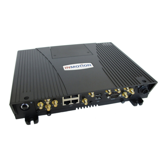
This section identifies the system components and describes the external interfaces of the system. 2.1. System Components The images below show the typical system components of the oMG 500. Figure 1 - oMG 500 Figure 2 - Power Cable Figure 3 - Multi-radio External Antenna The base unit contains the CPU, hard drive, and communication interface cards. -
Page 11: External Interfaces And Connectors
Figure 4 shows the external interfaces and connectors on the rear panel of the base unit. Note: there are different build options and configurations for the oMG 500 and your unit may not look exactly like this. For a full reference of all build options see the Sierra Wireless Knowledgebase. -
Page 12: Status Indicators
2.2.2. Status Indicators The oMG 500 has three external LEDs that indicate system status. These are located on the front-left corner of the top of the case. Figure 5 shows these indicators. Figure 5 - Status Indicators Table 2 describes the status LEDs and how to interpret them. - Page 13 500 Installation Guide System Description Software update is in progress. (DO Three rapid flashes, then off for one NOT REBOOT OR POWER DOWN second (repeating) THE oMG) On solid Network connection is up and normal Error status: either no card or network...
-
Page 14: Installing The Omg In A Vehicle
This section describes the procedure for installing the system along with important considerations and specific details where appropriate. 3.1. Basic Procedure The installation process for the oMG 500 varies depending on the specific application. The basic procedure includes the following steps: 1. Mount the base unit. 2. Mount the antenna. -
Page 15: Figure 6 - Bottom View-Dimensions And Clearance
500 Installation Guide Installing the oMG in a Vehicle Figure 6 - Bottom View—Dimensions and Clearance Figure 7 - Side View—Dimensions oMG-ED-130507 Rev 1.2 October 2, 2015... -
Page 16: Orientation
While the vehicle ignition is off, the oMG 500 is in sleep mode and draws less than 2 mA of current. When the ignition is turned on, the system starts its power-up sequence. When the ignition is turned off again, the system performs its controlled shutdown sequence before it resumes its sleep mode. -
Page 17: Connecting To The Omg 500
Connecting to the oMG 500 Figure 9 shows the power port on the rear panel of the oMG 500. To align the pins correctly, align the key on the power cord connector with the corresponding indentation on the port and fully insert the connector. -
Page 18: Figure 10 - Example Of Cable Stress Relief
500 Installation Guide Installing the oMG in a Vehicle Figure 10 - Example of Cable Stress Relief oMG-ED-130507 Rev 1.2 October 2, 2015... -
Page 19: Testing The Omg System After Installation
4. TESTING THE OMG SYSTEM AFTER INSTALLATION After completing the installation of the oMG 500 in a vehicle, perform the turn-up test described below to verify that the system operates properly. This procedure is typically performed by an IT specialist with experience in: •...
Need help?
Do you have a question about the oMG 500 and is the answer not in the manual?
Questions and answers