Table of Contents
Advertisement
Quick Links
Operation Manual
Charge/Discharge System
Charge/discharge System Controller
PFX2500 Series
PFX2512
PART NO. Z1-010-050, I0048801
Mar 2022
Description
Connecting and
Configuring Devices
PC Connection and
Hardware Configuration
Panel Operation and
Protection Function
Specifications
Volt/Thermometer Unit
OP02-PFX
8Slot Unit
SL01-PFX
Voltmeter Unit
OP03-PFX
Cleaning the Dust Filter
Characteristics of Digital
CC/CV Control
Explanation of Functions
Connecting to a Bias
Power Supply
Reference Data
Troubleshooting
1
2
3
4
5
6
7
App.
Options
Advertisement
Table of Contents

Related Manuals for Kikusui PFX2512


Summary of Contents for Kikusui PFX2512
- Page 1 PC Connection and Operation Manual Hardware Configuration Panel Operation and Protection Function Charge/Discharge System Specifications Charge/discharge System Controller PFX2500 Series Volt/Thermometer Unit PFX2512 OP02-PFX 8Slot Unit SL01-PFX Voltmeter Unit OP03-PFX App. Options Cleaning the Dust Filter Characteristics of Digital CC/CV Control...
-
Page 2: About This Manual
The specifications of this product and the contents of operation execute the tests, and analyze the test results. manual are subject to change without prior notice. The software application that you use to control the PFX2512 Charge/Discharge System Controller is BPChecker3000. © 2009 Kikusui Electronics Corporation This application is sold separately. -
Page 3: Checking The Package Contents
We recommend that you save all packing materials, in case the • DUT cable (+•–) (for connecting the DUT): 80 mm PFX2512 needs to be transported at a later date. • Sensing cable (voltage / temperature sensing cable) • I/F cable for PWR-01 DC power supply •... -
Page 4: Safety Symbols
In the EU, this product cannot be disposed of as domestic household waste. When disposing of this product, follow the Waste Electrical and Electronic Equipment (WEEE) Directive. In areas outside of the EU, dispose of it as per the instructions of the local authorities. PFX2512... -
Page 5: Safety Precautions
• This product is not designed or manufactured for general home or consumer use. Service Line • Kikusui service engineers will perform internal service of the Voltage product. If the product needs adjustment or repairs, contact Input power supply your Kikusui distributor or agent. -
Page 6: Precautions When Moving The Product
This may cause corrosion of various conductors or reduce the quality of the connector contacts inside the product, and this could lead to malfunction, failure, and possibly fire. • Do not install the product in a dusty location. PFX2512... -
Page 7: Notations Used In This Manual
Memo Notations used in this manual Indicates useful information. • In this manual, the PFX2512 Charge/Discharge System Controller is also referred to as the PFX2512 or the PFX2500 series. • Application software BPChecker3000 is also referred to as BPChecker3000. • The PWR-01 Series Regulated DC Power Supply is also referred to as the PWR-01. -
Page 8: Table Of Contents
Performing Stable System Operation 18 Component Names99 Combination for Performing Charge/Discharge Connecting the Power Cord 101 Tests 19 Connecting to the PFX2512 102 Procedure from System Configuration to Charge/ Connecting to a PC 103 Discharge Testing 25 Installing the Voltmeter Unit OP03-PFX 106... -
Page 9: Search By Topic9
• How do I perform discharge tests with p. 131 voltages that are lower than the minimum discharge operating voltage? Maintenance ➔“ Cleaning the Dust Filter” p. 125 • How do I clean the dust filter? Troubleshooting See “Troubleshooting” on page 135. PFX2512... -
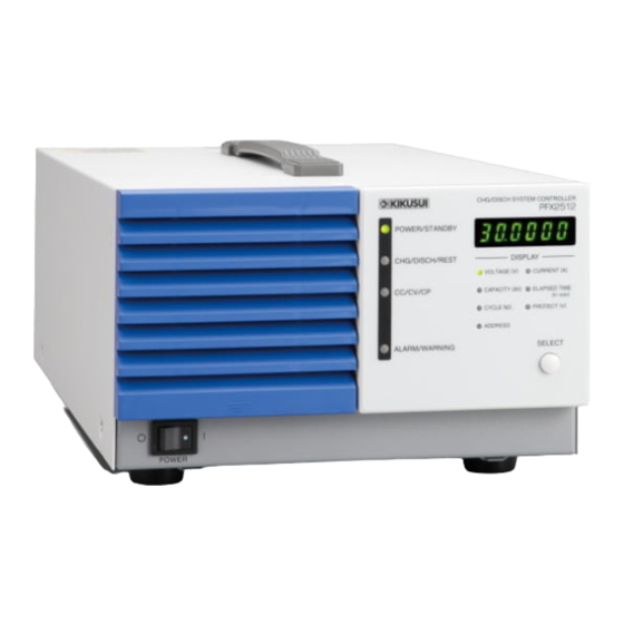
Page 10: Component Names10
It Illuminates when the current value is displayed. (when it is selected by the SELECT key) p. 66 12 ELAPSED TIME (h-min) LED It Illuminates when the elapsed time is displayed. (when it is selected by the SELECT key) PFX2512... - Page 11 28 AC INPUT connector AC inlet p. 54 LAN connector A connector for communicating with BPChecker3000 The terminal cover for protecting the input/output terminal is being attached to the terminal when the PFX2512 is shipped from the factory. PFX2512...
- Page 12 This page is intentionally blank. PFX2512...
-
Page 13: General Description
General Description This chapter describes the product, the devices that can be connected to the product, and the procedure from charge / discharge test preparation to test execution. -
Page 14: Product Overview
● Protection functions The PFX2512 has a built-in path switch (load switch). The path switch is equipped with a high- speed shutoff function that quickly detaches DC power supplies and electronic loads when an error is detected. - Page 15 High-speed charge / discharge switching control enables you to perform complicated charge / discharge tests with step times as short as 100 ms. The PFX2512 can be used to create a wide variety of test and simulation patterns for standard tests.
-
Page 16: System Configuration
Current detection Charge / Discharge System configulation (Example) The PFX2512 functional block is mainly made up of a DUT voltage / current / temperature measurement section, a digital constant current / constant voltage control section, a power supply / electronic load I / F section, a host communication control section, and a load switch. - Page 17 RS485 USB-RS485 converter The 1 channel of the charge and discharge system consists of one unit of each PFX2512, DC power supply, and Electronic load. The figure shown above is an example of system configuration for 2 channels of the charge and discharge system.
-
Page 18: Performing Stable System Operation
Performing Stable System Operation Ideal system shutdown when a power outage or sudden interruption occurs (executed automatically) The PFX2512 charge/discharge system Suggestions for the PC executing turns off. tests The PC remains on using the power from Install a UPS. Be sure to the UPS. -
Page 19: Combination For Performing Charge/Discharge Tests
Combination for Performing Charge/Discharge Tests With the PFX2512, the following combination can be used to perform charge / discharge tests. Model IDs are assigned to different combinations of devices used for charge / discharge tests. To p. 59 execute a charge / discharge test, you need to set an appropriate model ID according to the combination of devices to be connected. - Page 20 It may not be possible to use up to the power specified here due to loss in cables. Factory default settings A separate cable is required. For details, contact your Kikusui agent or distributor. Combinations whose model IDs have not been determined are planned to be available through version updates.
- Page 21 Voltage drops occur as a result of charge currents flowing through DUT cables, connection cables, PFX2512 current path circuits, and so on. Loss in cables is the power loss during charging due to this voltage drop. The maximum power that can be used for charging is the resultant value after subtracting the loss in cables.
- Page 22 Combination for Performing Charge/Discharge Tests Charge operation range of the DC power supply [PWR-01L] Voltage (V) DUT cable: At nominal cross-sectional area 14 mm PFX2512 Operating range PWR1201L PWR801L PWR401L Current (A) Charge operation range of the DC power supply [PWR-01ML]...
- Page 23 (Cutoff voltage) value Current (A) axis Constant current (CC Current) Discharge operating range of each electronic Load [PLZ-4W] Voltage (V) DUT cable: At nominal cross-sectional area 14 mm PFX2512 operating range PLZ1004W 2 units parallel operation PLZ1004W PLZ334W PLZ164W PLZ-4W...
- Page 24 Discharge operating range of each electronic Load [PLZ-5W] Voltage (V) DUT cable: At nominal cross-sectional area 14 mm PFX2512 operating range PLZ1205W 2 units parallel operation PLZ1205W PLZ405W PLZ205W PLZ-5W Minimum operating voltage Current (A) PFX2512...
-
Page 25: Procedure From System Configuration To Charge/Discharge Testing
Procedure from System Configuration to Charge/Discharge Testing To perform a charge / discharge test, configure a system with the PFX2512, DC power supplies, electronic loads, and PC, and control the system using application software BPChecker3000. The following procedure describes the main steps to configure a system, set test conditions, and start and stop tests. - Page 26 Start Io Config on BPChecker3000 to configure the hardware. Help Io Config Specify the channel that you want to configure on Io Config, and then set the PFX2512 p. 59 model ID. If you want to use temperature chambers, set the temperature chamber driver, VISA resource, and the number of temperature chambers.
-
Page 27: Connecting And Configuring Devices
Connecting and Configuring Devices This chapter describes how to connect and configure the devices. -
Page 28: Connecting The Power Cord
If obtaining an appropriate power cord is difficult, consult your Kikusui agent or distributor. • A power cord with a plug can be used to disconnect the PFX2512 from the AC line in an emergency. Connect the plug to an easily accessible power outlet so that the plug can be removed from the outlet at any time. - Page 29 • Only use the breaker with this PFX2512. • Keep the breaker readily accessible at all times. • Indicate that the circuit breaker is dedicated for use with this PFX2512 and that it is used to disconnect the product from the AC power line.
-
Page 30: Connecting The Devices
The PFX2512 does not come with cables for connecting to the DUT (battery). Prepare the necessary cables for each device. There is an optional TL08-PFX cable set that contains cables for connecting the PFX2512 to the DUT p. 123 (battery). - Page 31 Select the appropriate cable. p. 30 Attach an M6 solderless terminal to the PFX2512 end of the cable. If the DUT will be subject to high temperature, such as by placing it in a temperature chamber, pay CAUTION attention to the allowable temperature of the DUT cable. If the heat resistance of the DUT cable and the like is insufficient, the DUT will be in a dangerous situation due to poor insulation, increased contact resistance, and so on.
- Page 32 Discharge System Controller (PFX2512), 1 set the DC power supply (PWR1201ML), and 2sets of the Electronic load (PLZ1205W) in parallel operation. As for the parallel operation of the Electronic load units (PLZ1205W), locate the master unit with a position nearest to the PFX2512. DUT cable...
-
Page 33: Connecting To Dc Power Supplies
Connecting to DC Power Supplies Connect the PFX2512 to the DC power supply using the cable with the solderless terminal and the p. 25 I/F cable. This section explains an example of connecting a Kikusui PWR-01 Regulated DC Power Supply (L type, ML type) using the optional SC007-PFX I/F cable for the PWR-01. - Page 34 Cable diameter halves of the OUTPUT (including the insulation) terminal cover have ø8 to ø17 different shapes. Top half of the cover Example of the load cable position Insert the adapter tabs into the two cuts in the top half PFX2512...
- Page 35 Place the top half of the OUTPUT terminal cover over the bottom half, and screw them together. Make sure that the screws are securely fastened. After you have lined up the top and bottom halves of the cover, use the screws to fix the cover in place. Screw (M3) PFX2512...
- Page 36 Memo connector of the PFX2512. If you reverse the cable Insert the end with a ferrite core into the PFX2512. ends, it will not work. Insert it securely using the lock lever. Check that it does not fall out. Lock lever...
-
Page 37: Connecting To The Electronic Load
Connecting to the Electronic Load Connect the PFX2512 to the Electronic load using the cable with the solderless terminal and the I/F p. 25 cable. This section explains an example of connecting a Kikusui PLZ-5W Electronic Load using the optional SC005-PFX I/F cable for the PLZ-5W. - Page 38 (2) If solderless terminal is small solderless terminal PLZ1205W example Place the bottom half of the cover for the load input terminals on the rear panel underneath the cables connected to the load input terminals. PLZ1205W example PFX2512...
- Page 39 Push the cover for the load input terminals on the rear panel against the panel, and fasten it with the included screws. Make sure that the screws are securely fastened. M3×18 PFX2512...
- Page 40 PFX2512. If you reverse the cable Insert the end with a ferrite core into the PFX2512. ends, it will not work. Confirm that the lock lever is pulled down and it is firmly connected.
-
Page 41: Preparing To Connect The Dut (Battery)
Preparing to Connect the DUT (Battery) The PFX2512 does not come with cables for connecting to the DUT (battery). Prepare the following cables according to the DUT (battery). There is an optional TL08-PFX cable that contains cables for connecting PFX2512 and the DUT p. - Page 42 Temperature measurement terminal. Connect the included thermistor. –T Temperature measurement terminal. Connect the included thermistor. Shield grounding terminal. This is connected to the PFX2512 chassis. Do not connect the shield electric potential anywhere on the DUT (battery). Using AWG 24 to 20 (0.20 mm to 0.52 mm...
-
Page 43: Connecting The Dut (Battery)
• After connecting the devices, connect the PFX2512 to the DUT (battery). Connect the PFX2512 side first. • When installing a fuse between the PFX2512 and DUT (battery), be sure to turn off the POWER switch, and turn off the circuit breaker of distribution. - Page 44 Connecting the DUT (Battery) Connecting the PFX2512 to the DUT (Battery) Check that the PFX2512 is ready to execute tests (power-on state). You can connect or disconnect DUT cables and sensing connectors even when the power switch is on. But, make sure that a charge/discharge test is not in progress.
-
Page 45: Configuring The Devices
Configuring the PFX2512 You can change the following settings using the S1 switch on the rear panel. If you change a setting, turn the PFX2512 off and then back on. • Channel numbers • Vibration sensor Signal name... - Page 46 (set the switch to 1). • If you want to set the vibration sensor to on (set the switch to 1), install the PFX2512 as upright as possible in a location without vibration or the like. If the installation is inappropriate, the SHOCK DETECT alarm may be activated preventing you from performing tests.
-
Page 47: Configuring The Dc Power Supply
• No adjustment is necessary between connected devices. Setting Protection Functions If the PFX2512 is disconnected from the DUT (battery) as a result of a DUT protection circuit or fuse being activated during a charge/discharge test, high voltage may be generated temporarily depending on the connected power supply. - Page 48 If the DC power supply’s OVP or OCP is activated during a charge/discharge test, PS/B alarm occurs p. 70 on the PFX2512, and the output is turned off. Turn off the DC power supply, and eliminate the cause of the alarm. Then, turn on the DC power supply, and clear the alarm from BPChecker3000.
-
Page 49: Configuring The Electronic Load
To protect the connected devices, set the protection function of the electronic load. Configure external analog control to enable the electronic load to be controlled from the PFX2512. When the Electronic load is connected in parallel operation, assign the master unit and the slave unit. - Page 50 If the Electronic load OCP or other alarm is activated during a charge / discharge test, CD/B alarm p. 70 occurs on the PFX2512, and the load is turned off. Press ENTER on the Electronic load and eliminate the cause of the alarm. Then, clear the alarm from BPChecker3000.
- Page 51 In Menu setting, power cycle the PLZ-4W after finishing the menu setup. The new setting is confirmed by power cycling the PLZ-4W. For details on the setup procedure, see the operation manual of the electronic load that you are using. PFX2512...
- Page 52 Hold down LOCK (SHIFT+LOCAL) to lock or unlock the panel. While the panel is locked, a key icon is shown in the display. For details on the setup procedure, see the operation manual of the electronic load that you are using. PFX2512...
-
Page 53: Pc Connection And Hardware Configuration
PC Connection and Hardware Configuration This chapter explains hardware configuration using application software BPChecker3000 for connecting to a PC and performing charge / discharge tests. -
Page 54: Connecting To A Pc
Connecting to a PC PFX2512 is controlled using application software BPChecker3000. PFX2512is connected to a PC through the LAN interface and assigned an IP address. The following three connection methods are available. The LAN cable can be a straight cable or a crossover cable. - Page 55 You can connect directly (a single unit) or connect through a switching hub (multiple units). Connecting directly to a PC (only when using a single unit) If you will use only a single unit, use a LAN cable to connect it to the PC. PFX2512 PFX2512 To the LAN port...
-
Page 56: Assigning Ip Addresses
You have to set the IP address and subnet mask on the PC that you are using to values that match the IP address range of the PFX2512. If the PC’s IP address and subnet mask are not set correctly, you will not be able to connect to the PFX2512. - Page 57 If you have other channels you want to use, repeat step 4 to step 5 . When you finish configuring all the channels, turn the PFX2512 off and then back on. To verify whether the IP address has been set correctly, check using the PFX2512 panel. p. 58 PFX2512...
-
Page 58: Checking The Ip Address
Checking the IP address The indication on the display varies depending on how the IP address is assigned. Turn on the router or switching hub, PC, and then the PFX2512. Memo The voltage display appears on the PFX2512. If you do not turn the... -
Page 59: Setting The Model Id
Setting the Model ID Set the model ID, which identifies the combination of DC power supply and electronic load that are p. 19 connected to the PFX2512, in the PFX2512. model ID DC power supply Electronic Load Maximum Maximum discharge power... - Page 60 The Setting of Model ID dialog box closes, and the model ID is displayed. Click Send. The model ID is sent to the selected PFX2512. Setting of the model ID is complete. You can check whether the ID has been assigned correctly by clicking Search under Select Ch.
-
Page 61: Configuring Temperature Chambers
Turn on the router or switching hub, PC, and then the PFX2512. Start IO Config. Click the channel selection search button, check that the PFX2512 you want to configure is displayed, and then click Connect. If a different channel is displayed, select the appropriate channel. - Page 62 This page is intentionally blank. PFX2512...
-
Page 63: Panel Operation And Protection Function
Panel Operation and Protection Function This chapter explains how to turn on the power and how to select displays; provides an overview of external control and monitoring; and describes the protection function and warning function. -
Page 64: Turning The Power On And Off
Example of firmware version 1.00 A few seconds later Example of channel number 1 If the POWER switch is turned on for the first time after purchase, the PFX2512 starts up using p. 19 factory default settings. If the ALARM/WARNING LED is lit, an alarm or protection function may be activated. - Page 65 Risk of malfunction. CAUTION • After you turn the PFX2512 POWER switch off, wait at least 10 seconds before you turn it back on. Do not turn the power on and off repeatedly. • Do not turn off the POWER switch while a charge/discharge test is in progress.
-
Page 66: Selecting The Display
LAN interface Overview of External Control In addition to controlling the PFX2512 from the front panel, the EXT CONT terminal on the rear panel can be used to perform the following controls. • External monitoring of the operating status •... - Page 67 Not used Do not connect anything to this pin. Shorting this pin with the external alarm common causes the PFX2512 to enter external alarm mode and the test to be aborted. Status common pins 4 and 8 are at the same electric potential.
-
Page 68: Protection Function And Warning Function
An error in the two hundreds (Err. 2xx) indicates an internal error. It can be caused by power supply line or communication noise. Restart the PFX2512 and BPChecker3000 to see if the error clears. If such errors occur frequently, check the error number, and contact your Kikusui agent or distributor. - Page 69 Protection Function and Warning Function Setting: “PFX” indicates that it is set on the PFX2512. “BPC” indicates that it is set with BPChecker3000. “Fixed” indicates that it is always detected. Panel Cause of alarm and description Behavior Setting display Err.001...
- Page 70 Clearing warnings Remove the root cause of the warning. If the warning still occurs even after you have corrected all the causes of the warnings, the PFX2512 may be malfunctioning. Stop using the PFX2512 immediately, and contact your Kikusui agent or distributor.
-
Page 71: Specifications
Specifications This chapter provides PFX2512’s specifications and outline drawing. -
Page 72: Pfx2512 Functional Specifications
PFX2512 Functional Specifications • Static: General term to indicate CC charge, CC - CV charge, CC discharge, CC - CV discharge, CP discharge, and CP - CV discharge • Pattern: General term to indicate pattern charge/discharge and I-V characteristics charge/... - Page 73 PFX2512 Functional Specifications Discharge function Static Constant current Setting Constant current value (Current) discharge Cutoff Specified time after discharge start (Discharge Time) condition Battery voltage (Cutoff Voltage) Capacity calculation voltage (Capacity Voltage) Battery temperature (Max Temp) Discharge capacity (Discharge Ah)
- Page 74 PFX2512 Functional Specifications Pattern charge/discharge function (seamless charge/discharge control) Pattern Pattern constant Setting Step constant current value (Step Current) current discharge Step time (Step Time) CC Pattern Cutoff Time since pattern charge/discharge start (Total Time) condition or Number of loops (Loop Count) limit Limit voltage (Limit;...
- Page 75 PFX2512 Functional Specifications Measurement function Voltmeter and ammeter Static Battery voltage Average voltage every 100 ms (Voltage) Charge/discharge current Average current every 100 ms (Current) Battery temperature Simple thermometer function using a thermistor (Temperature) Capacity Integration of the measured current (average current) and the elapsed time...
- Page 76 Direct detection using a hardware comparator Output off PFX2512 Overheat protection (OHP) Detects abnormal temperature in the path switch When the temperature returns normal, the PFX2512 returns to the idle state. Overcharge / overdischarge capacity Detects overcharge capacity using current integration judgment; turns protection (OAH)
- Page 77 PFX2512 Functional Specifications Other functions Range switching Voltage range -1.0000 to 6.0000 The display resolution is 100 μV. 60 V -6.0000 to 60.0000 Pattern charge/discharge function Response within 50 ms (TYP) (seamless charge/discharge control) Can control DC power supplies and electronic loads at the same time in order to seamlessly switch between charge and discharge.
-
Page 78: Pfx2512 Electric Specifications
PFX2512 Electric Specifications Unless specified otherwise, the specifications are for the following settings and conditions. • The warm-up time is 30 minutes. • TYP (typical) values do not guarantee the performance. • reading: Indicates the readout value. • set: Indicates the setting value. - Page 79 PFX2512 Electric Specifications Setting accuracy Static Constant current 0.000 A to 50.000 A Range charge/discharge Accuracy Resolution 1 mA Constant voltage 60 V range 0.000 V to 60.000 V Range charge/discharge 6 V range 0.000 V to 6.000 V Accuracy...
- Page 80 PFX2512 Electric Specifications Measurement accuracy Static Charge/ Range 0.0000 A to 50.0000 A discharge ±(0.15 % of reading + 0.02 % of rating) Accuracy current measurement Resolution 0.1 mA Voltage Range 60 V range -6.0000 V to 60.0000 V measurement 6 V range -1.0000 V to 6.0000 V...
- Page 81 PFX2512 Electric Specifications Measurement accuracy (continued) High-speed sampling Current -50.0000 A to 50.0000 A Range measurement Accuracy 1 ms sampling ±(0.2 % of reading + 0.5 % of rating) 2 8 9 10 ms sampling ±(0.15 % of reading + 0.05 % of rating) 100 ms sampling ±(0.15 % of reading + 0.02 % of rating)
- Page 82 PFX2512 Electric Specifications Protection functions Overvoltage (overcharge) protection Software OVP Setting range 0 % to 105 % of rating Setting 60 V range Depends on the voltmeter accuracy accuracy 6 V range Depends on the voltmeter accuracy Resolution 1 mV Activation time 150 ms max.
- Page 83 (length: approx. 3 m, connector area: with cover, with core). This is a Class I equipment. Be sure to ground the PFX2512's protective conductor terminal. The safety of this product is only guaranteed when the product is properly grounded.
- Page 84 PFX2512 Electric Specifications This is a Class A equipment. The PFX2512 is intended for use in an industrial environment. This product may cause interference if used in residential areas. Such use must be avoided unless the user takes special measures to reduce electromagnetic emissions to prevent interference to the reception of radio and television broadcasts.
-
Page 85: Volt / Thermometer Unit Op02-Pfx (Option)
Volt / Thermometer Unit OP02-PFX (Option) This chapter describes how to install the optional Volt/Thermometer Unit OP02-PFX and how to connect the DUT (battery) to the unit and contains the unit’s specifications. -
Page 86: Installing The Volt/Thermometer Unit Op02-Pfx
Volt / Thermometer Unit (Option) Installing the Volt/Thermometer Unit OP02-PFX By installing an Volt/Thermometer Unit OP02-PFX in an option slot on the PFX2512, you can increase the number of voltmeter and thermometer measurement points. If OP02-PFX units are installed in all option slots, voltage and temperature measurement points can be expanded to 12 points. - Page 87 Installing the Volt/Thermometer Unit OP02-PFX Remove the cover. PFX2512 Insert the board. PFX2512 Installing an OP02-PFX Connector area To remove an installed OP02-PFX, unfasten the screws, and pull the board out by holding the input terminal area. PFX2512 Hold here...
-
Page 88: Preparing To Connect The Dut (Battery)
PFX2512 and the DUT (battery) is shown The TL09-PFX option consists of a dedicated voltage sensing cable and thermocouple for p. 123 connecting the DUT (battery) to a PFX2512 in which an OP02-PFX is installed. PFX2512... - Page 89 Preparing to Connect the DUT (Battery) ■ Input terminal (connector MC1.5/10-G: Phoenix Contact) When the PFX2512 is shipped from the factory, connectors are attached to the input terminals. If they are damaged or lost, 84-61-7910 contact your Kikusui agent or distributor.
- Page 90 Voltage sensing connection terminal 4 Voltage sensing connection terminal 3 Voltage sensing connection terminal 2 Voltage sensing connection terminal 1 Voltage sensing Attached Up to 5 m in length connector side connector plug Shield potential of the rear panel PFX2512...
-
Page 91: Connecting The Dut (Battery)
( p. 130 • CC-CV, CP, and CP Pattern are controlled by the PFX2512 voltage sensing function. Be sure to connect the PFX2512 voltage sensing cables to the DUT. • Risk of damaging the DUT. -
Page 92: Volt/Thermometer Unit Op02-Pfx Specifications
Volt/Thermometer Unit OP02-PFX Specifications Items not listed are the same as those of the PFX2512. • reading: Indicates the readout value. • set: Indicates the setting value. • rating: Indicates the rated. • Static: General term to indicate CC charge, CC - CV charge, CC discharge, CC - CV discharge, CP discharge, and CP - CV discharge •... - Page 93 Cell measurement function Static Cell voltage Average voltage every 100 ms (Cell Voltage) Cell Temperature Thermometer function using a thermocouple, updated every second (Cell Temperature) PFX2512...
- Page 94 ±(0.05 % of reading + 0.02 % of rating) Measurement accuracy Resolution 0.1 mV Measured value Average voltage every 100 ms Measurement interval 100 ms You can apply a voltage from -20 V to 22 V. ° ° Ambient temperature at 18 C to 28 PFX2512...
- Page 95 Screws 2 pcs. Handling of the product 1 copy When installed in the PFX2512. Shared with the voltage/temperature sensing input terminal. Indicates the terminals for connecting the DUT (the DUT’s positive terminal and the DUT’s negative terminal). This indicates the resistance between measurement terminals.
- Page 96 This page is intentionally blank. PFX2512...
-
Page 97: 8Slot Unit Sl01-Pfx (Option) Voltmeter Unit Op03-Pfx (Option)
8Slot Unit SL01-PFX (Option) Voltmeter Unit OP03-PFX (Option) This chapter describes how to connect the optional 8Slot Unit SL01-PFX, how to install the Voltmeter Unit OP03-PFX, and how to connect the DUT (battery) and contains the specifications. -
Page 98: Sl01-Pfx 8Slot Unit
If Voltmeter Units OP03-PFX are installed in all SL01-PFX slots, voltage measurement points can be expanded to 64 points. Further, by installing Volt / Thermometer Units OP02-PFX in the PFX2512, you can increase the number of measurement points to 72. -
Page 99: Component Names99
Component Names Front panel SLOT UNIT SL01 - PFX POWER/ ALARM No. Name Function — Louver For cooling. Lights when the power is on (POWER: green) and when a slot alarm is detected p. 112 POWER/ALARM LED (ALARM: red) PFX2512... - Page 100 — Not used. A connector for using multiple units. SYNC OUT connector p. 102 SYNC IN connector Connector for the EX01-PFX (PFX2512 main unit) Voltmeter Unit p. 106 An option board for expanding the number of voltage measurement points (OP03-PFX) p.
-
Page 101: Connecting The Power Cord
3 m or less in length. If obtaining a power cord is difficult, contact your Kikusui agent or distributor. • The power cord with a plug can be used to disconnect the SL01-PFX from the AC power line in an emergency. -
Page 102: Connecting To The Pfx2512
SL01-PFX SYNC IN connector Install the EX01-PFX in the leftmost available option slot of the PFX2512. If OP02-PFX units are installed, install the EX01-PFX in the leftmost available slot to the right of the OP02-PFX units. Check that all devices that you will connect are turned off. -
Page 103: Connecting To A Pc
Connecting to a PC Insert the other end of the 14-core flat cable into the SYNC OUT connector of the EX01-PFX installed in the option slot of the PFX2512. Use the lock lever to secure it. Check that it does not fall out. - Page 104 Assigning the IP address automatically (connecting through a router) If you connect through a router that has a DHCP server feature, the IP address is assigned p. 54 automatically. Connection EX01-PFX PFX2512 Router PFX2512 to the LAN port SYNC OUT connector...
- Page 105 If the IP address is already decided, you can connect using a fixed IP address. p. 56 The IP address is set to the number obtained by adding 20 to the xxx section of the PFX2512’s IP address xxx. xxx. xxx. xxx.
-
Page 106: Installing The Voltmeter Unit Op03-Pfx
Using the screws included with the OP03-PFX, fix the board to the panel. Be sure to use the included screws. The first time that you install OP03-PFX units after purchase, use the Help Io Config, Test Condition Editor of BPChecker3000 to set the number of OP02-PFX units. Test Condition Editor PFX2512... - Page 107 Insert the board. SL01-PFX Installing an OP03-PFX Connector area To remove an installed OP03-PFX, unfasten the screws, and pull the board out by holding the input terminal area. SL01-PFX Hold here Removing an OP03-PFX Hold here Input terminal area PFX2512...
-
Page 108: Preparing To Connect The Dut (Battery)
Example of connecting the DUT (battery) to an SL01-PFX after installing an Voltmeter Unit OP03-PFX The TL11-PFX / TL12-PFX [CE compliant product] option consists of a dedicated voltage sensing cable and thermocouple for connecting the DUT (battery) to a PFX2512 in which an p. 123 , p. 123 OP03-PFX is installed. - Page 109 Preparing to Connect the DUT (Battery) ■ Input terminal (connector MC1.5/10-G: Phoenix Contact) When the PFX2512 is shipped from the factory, connectors are attached to the input terminals. If they are damaged or lost, 84-61-7910 contact your Kikusui agent or distributor.
- Page 110 ・7 Voltage sensing connection terminal 3 ・6 2・6 Voltage sensing connection terminal 2 ・5 1・5 Voltage sensing connection terminal 1 Voltage sensing Attached Up to 5 m in length connector side connector plug Shield potential of the rear panel PFX2512...
-
Page 111: Connecting The Dut (Battery)
( p. 130 • CC-CV, CP, and CP Pattern are controlled by the PFX2512 voltage sensing function. Be sure to connect the PFX2512 cell voltage sensing cables to the DUT. • Risk of damaging the DUT. If you leave the cell voltage sensing cables connected to the DUT, the DUT will continue to discharge a minute current. -
Page 112: Turning The Sl01-Pfx On And Off
Finally, the display enters voltage display mode. The PFX2512 is ready to execute tests (POWER state) and can receive commands from BPChecker3000. If the POWER switch is turned on for the first time after purchase, the PFX2512 starts up using p. 59 factory default settings. - Page 113 Risk of malfunction. CAUTION • After you turn the PFX2512 POWER switch off, wait at least 10 seconds before you turn it back on. Do not turn the power on and off repeatedly. • Do not turn off the POWER switch while a charge/discharge test is in progress.
-
Page 114: 8Slot Unit Sl01-Pfx Specifications
1 copy OP02-PFX cannot be installed. IP address setting is either a fixed IP address (address that results by adding 20 to the PFX2512 address is automatically assigned) or an IP address automatically assigned by a DHCP server. Connects to an extension board. - Page 115 Installed in the SL01-PFX by factory default. Outline drawing 4-M3 screw holes, max. depth 6 mm 275 (10.83) 70 (2.76) (0.24 inch) MAX410 (16.14) 214.5 (8.44) 400 (15.75) MAX20 (0.79) Unit mm (inch) PFX2512...
-
Page 116: Voltmeter Unit Op03-Pfx Specifications
Voltmeter Unit OP03-PFX Specifications Items not listed are the same as those of the PFX2512. • reading: Indicates the readout value. • set: Indicates the setting value. • rating: Indicates the rated. • Static: General term to indicate CC charge, CC - CV charge, CC discharge, CC - CV discharge, CP discharge, and CP - CV discharge •... - Page 117 The maximum and minimum cell voltages are calculated for the cells in the object under measurement, and charging finishes when the difference between these two values exceeds the set value. Cell measurement function Static Cell voltage Average voltage every 100 ms (Cell Voltage) PFX2512...
- Page 118 ±(0.05 % of reading + 0.02 % of rating) Measurement accuracy Resolution 0.1 mV Measured value Average voltage every 100 ms Measurement interval 100 ms You can apply a voltage from -20 V to 22 V. ° ° Ambient temperature at 18 C to 28 PFX2512...
- Page 119 Handling of the product 1 copy When installed in a SL01-PFX Shared with the voltage sensing input terminal. Indicates the terminals for connecting the DUT (the DUT’s positive terminal and the DUT’s negative terminal). This indicates the resistance between measurement terminals. PFX2512...
-
Page 120: Mounting To The Rack
Mounting to the rack You can mount SL01-PFX to a rack. To rack mount the SL01-PFX, you need a rack mounting option. For information about options, contact your Kikusui agent or distributor. Rack mount option Name Model Note Rack mount frame... -
Page 121: A Options
Appendix A Options B Cleaning the Dust Filter C Characteristics of Digital CC/CV Control D Explanation of Functions E Connecting to a Bias power supply F Reference Data G Troubleshooting... - Page 122 To reinstall the handle that has been removed, use screw locking agent (e.g., 1401B by ThreeBond International, Inc.) to prevent screws from loosening. We recommend that you keep all pieces that you have removed from the PFX2512. You will need these pieces if you remove the PFX2512 from the rack.
- Page 123 Options Load cable TL08-PFX This is a dedicated load cable for connecting the PFX2512 and the DUT (battery). Because the cables and sensing cables that are necessary for making this connection are already assembled, connection is easy. Sensing cable set TL09-PFX (for OP02-PFX)
- Page 124 8Slot Unit SL01-PFX This is an expansion slot for the measurement function. You can increase the number of voltage measurement points by connecting to a PFX2512 using the included EX01-PFX. It is used by installing OP03-PFX units (sold separately). Up to 8 boards can be installed.
-
Page 125: B Cleaning The Dust Filter
• If the dust filter is clogged, the product’s internal cooling capabilities will be reduced. • When the PFX2512 is in operation, air is sucked through the dust filter to cool the inside of the device. If moisture is present in the dust filter, the temperature or humidity inside the PFX2512 increases. - Page 126 Characteristics of Digital CC/CV Control The constant current (CC)/constant voltage (CV) control on the PFX2512 is performed digitally. This section describes the characteristics and operation principle of digital CC/CV control so that you can efficiently conduct evaluation tests. ● Digital CC/CV control is not susceptible to the performance of the connected DC power supplies or electronic loads and constantly enables high-accuracy CC/CV control.
- Page 127 IEC standards. This is a useful feature for the step operations that are required when you are simulating charge/discharge tests. Seamless charge/discharge switching Traditional charge/discharge switching Charge Charge Charge Charge 1 to 3 s 1 to 3 s Discharge Discharge App. PFX2512...
-
Page 128: D Explanation Of Functions
PFX2512 Charge/Discharge System Controller. Description of the measurement function The PFX2512 is equipped with a 24-bit resolution delta-sigma high-speed A/D converter for taking measurements. It can measure at high speed and with high accuracy over a wide measurement range of 60 V/50 A at a resolution of 100 μV/100 μA without changing the range. - Page 129 Detection may be difficult for poor contact and other situations. In other words, the function does not check the connection status completely. Voltage measurement of the voltage sensing cable Voltage measurement of the DUT cable DUT (battery) voltage An alarm occurs at 100 mV or higher. Approx. 200 ms App. PFX2512...
- Page 130 7.4 V The unbalance detection function only works The function is affected by the resistance on cells of the same type and same voltage. between the cells and the protection switch resistance, and it cannot measure the correct cell voltages. PFX2512...
- Page 131 The current capacity of the PFX2512 is 50 A, so when you connect a 5 V bias power supply, configure the settings so that the power capacity is at least 5 V x 50 A=250 W.
- Page 132 (AWG6) or more, 50 cm or less, See Table “Nominal cross-sectional area of wires and allowable currents (reference)” (p. 28 Cable to connect the PLZ-4W DUT cable included with the PFX2512 and the bias power supply PFX2512 We recommend that you make this cable...
- Page 133 Reference Data Reference Data PFX2512 pattern charge/discharge The data is acquired under the following conditions. System requirements Charge/discharge system controller PFX2512 Power supply PWR800L Electronic Load PLZ1004W The DUT (battery) Use a 14 mm cable with a length of 5 m to connect to a 25.9 V, 40 Ah Li-ion battery module.
- Page 134 The rising and falling waveforms of the pattern current (measured by the current probe) Setting conditions 2 values CC pattern charge/discharge 50 A (CHG) Step 1 CHG: 50 A 500 ms Step 2 DISCHG: 50 A 500 ms 0 A -50 A (DISCH) PFX2512...
-
Page 135: G Troubleshooting
If errors are large even under different conditions, the product — adjustment may be off. Contact your Kikusui agent or distributor. The voltage display is unstable. If the connected DUT is not a battery or if the DUT is connected yet to —... - Page 136 The first time that you use the product after purchase, use been expanded. p. 86 BPChecker3000 to customize the model ID. Io Config Help p. 106 Did you set the number of OP02-PFX or OP03-PFX boards? Set the number of boards using BPChecker3000. Test Help Condition Editor PFX2512...
- Page 137 68 greatly distorted, this alarm may be triggered by mistake, or measurements may fluctuate. Install a line filter or the like if necessary. The PFX2512 overheat protection function of the power circuit may is displayed on the have been activated.
- Page 138 Check the system connections. This alarm also occurs if window. the PFX2512 power supply is cut off temporarily. For details on how to p. 68 restore the system after a power outage, see the BPChecker3000 help file.
- Page 139 BPChecker3000 help file. Test Executive Help The PC and PFX2512 suddenly If both the PC and PFX2512 stop, restart the PFX2512 first and then the stopped. For details, see “When a power failure occurs on the host PC side or on —...
- Page 140 Troubleshooting This page is intentionally blank. PFX2512...
- Page 141 Index accessories ..................3 Firmware version ................2 alarm front panel clearing ................70 PFX2512 ................10 Application software ..............16 SL01-PFX ................99 BPChecker3000 ................16 I/F cable for DC power supply SC07-PFX ......124 connection ..............54 I/F cable for Electronic load SC05-PFX .........124 IP address setting PC ..................
- Page 142 ............127 Power cord ..................28 power cord ..................28 POWER switch ..............64 rack mount frame .............120 rear panel PFX2512 ................11 SL01-PFX ................ 100 seamless charge/discharge ............ 127 sensing cable connection ...............44 construction ..............42 sensing cable set TL09-PFX ............ 123 sensing cable set TL11-PFX ............
- Page 144 In either case, please contact your Kikusui agent or distributor. At that time, inform your agent or distributor of the “Part No.” written on the front cover of this manual.
Need help?
Do you have a question about the PFX2512 and is the answer not in the manual?
Questions and answers