Table of Contents
Advertisement
User's Manual
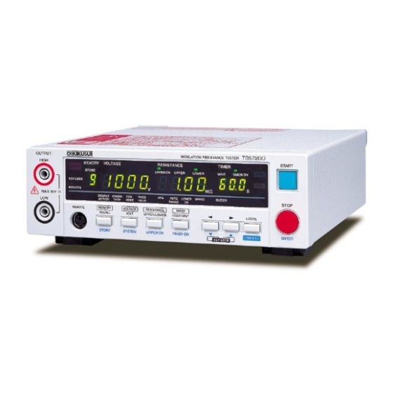
Insulation Resistance Tester
TOS7200
DANGER
This Tester generates high voltage!
Any incorrect handling may cause death.
Read Chapter 3 "Safety Precautions during Testing"
in this manual to prevent accident.
Keep this manual near the tester for easy access
of the operator.
No. IB028912
Jul. 2018
1. Preface 11
Connectors 39
Advertisement
Table of Contents

Subscribe to Our Youtube Channel
Related Manuals for Kikusui TOS7200


Summary of Contents for Kikusui TOS7200
-
Page 1: Table Of Contents
No. IB028912 Jul. 2018 User’s Manual 1. Preface 11 Insulation Resistance Tester 2. Preparation 14 TOS7200 3. Safety Precautions during Testing 19 4. Basic Operation 23 5. Using Terminals and Connectors 39 6. Maintenance 49 7. Specifications 51 DANGER This Tester generates high voltage! Any incorrect handling may cause death. -
Page 2: About The Tos7200 Manuals
Unpacking computer. TOS7200 Manuals are intended for users of the Insulation Upon receiving the product, confirm that the necessary Resistance Tester and their instructors. Explanations are given accessories are included and have not been damaged in transit. -
Page 3: To Supervisor In Charge Of Operation
• the test leadwires connected to the output terminal • the Device Under Test (DUT) • any part of the Tester, which is electrically connected to the output terminal, and • the same part as above immediately after the output has been cut off. TOS7200... -
Page 4: Safety Precautions
When moving or transporting the product to the installation location, be sure to observe the “Precautions to Be Taken When Moving the Product” in the Safety information manual. Item specific to this product are given below. • Retract the legs. TOS7200... -
Page 5: Contents
Ending the test ....31 Outline of the TOS7200 ... . . 11 PASS judgment . - Page 6 General specifications ....55 Dimensions..... . . 56 Index........57 TOS7200...
-
Page 7: Front Panel
The location of the cursor is indicated by a blinking 7-segment LED on the display unit. This blinking will stop if no keystroke is entered for 5 seconds or more. TOS7200... -
Page 8: Display
(during testing). When the result of a pass/fail judgment is PASS, this LED lights. p. 31 PASS lamp When the result of a pass/fail judgment is FAIL, this LED lights. p. 32 FAIL lamp TOS7200... - Page 9 Lights up when the tester is in KEYLOCK state. p. 37 Lights up when the tester is remotely controlled through the RS232C REMOTE LED — interface. When lit, all inputs except the STOP switch are not accepted. To return to local mode, press LOCAL (SHIFT). TOS7200...
-
Page 10: Rear Panel
This terminal outputs the voltage that corresponds to the measured p. 48 resistance value. OUTPUT terminals These terminals output the test voltage. They are connected in parallel to the OUTPUT terminals on the front p. 16 panel. For details, see the communication interface manual. TOS7200... -
Page 11: Preface
Preface Outline of the TOS7200 The TOS7200 is an insulation resistance tester that is available in a wide range of electric and electronic components and equipment, and allows any test voltage to be set. Because it features the window comparator and timer function, the tester is capable of efficiently conducting insulation resistance tests based on various safety standards. -
Page 12: Rc01-Tos/Rc02-Tos Remote-Control
When the OPERATE switch is ON and the tester is in ready status, pressing this switch starts testing. • STOP switch This switch is used to shut off the output voltage or cancel a FAIL judgment. It serves the same function as the STOP switch on the front panel of the tester. TOS7200... - Page 13 RC01-TOS: 200 mm (W)×70 mm(H)×39 mm (D) RC02-TOS: 330 mm (W)×70 mm (H)×39 mm (D) Connection of a remote-control box to the tester requires the use of a DIN-Mini DIN adapter. For DD-5P/6P DIN-Mini DIN adapter [84250], contact your Kikusui distributor/agent. TOS7200...
-
Page 14: Preparation
If the supplied power cord cannot be used because the rated voltage or the plug shape is incompatible, have a qualified engineer replace it with an appropriate power cord that is 3 m or less in length. If obtaining a power cord is difficult, contact your Kikusui agent or distributor. -
Page 15: Turning On The Power
When the power is turned on, the DANGER lamp lights, but no voltage is generated. Turning the POWER switch off. The POWER switch to turn the TOS7200 off. The panel settings that were in use immediately before the POWER switch was turned off are saved. -
Page 16: Connecting The Test Leadwires
Press the STOP switch. Confirm that the DANGER lamp is off. Connect the high voltage side test leadwire to the HIGH terminal. Short-circuit the low voltage side and high voltage side test leadwires to confirm that no high voltage is output. TOS7200... -
Page 17: Connecting To The Dut
VOLTAGE VOLTAGE RESISTANCE RESISTANCE TIMER TIMER TOS7200 AC LINE Grounded DUT Insulation resistance test across the AC LINE and chassis of the DUT Risk of electric shock. Never touch a test leadwire, the DUT, the HIGH terminal, or the WARNING LOW terminal during a test (or while the DANGER lamp is lit). -
Page 18: Connecting To An Ungrounded Dut
Ungrounded DUT Disconnecting Test Leads from the DUT Check that the DANGER lamp is off. Remove the high voltage side test leadwire from the TOS7200 HIGH terminal. Remove the high voltage side test leadwire from the DUT. Remove the low voltage side test leadwire. -
Page 19: Safety Precautions During Testing
• When a test is started without the test leadwires connected to each other in the UPPER OFF condition, a FAIL judgment must not be made. • When a test is started with the test leadwires short-circuited in a LOWER ON condition, a FAIL judgment must be made. TOS7200... -
Page 20: Precautions On Testing
• Provide means to assure that the test setup does not become the test voltage is being delivered by inadvertent operation. • Provide means to assure that none can touch the DUT, test leadwires, HIGH terminal, and LOW terminal when the test voltage is being delivered. TOS7200... -
Page 21: Warning For Residual High Voltages
You may do either (a) or (b) first. But be sure to do both. (a) Turn OFF the power switch of the Tester. (b) Disconnect the AC power cord of the Tester from the AC line receptacle. TOS7200 ... -
Page 22: Prohibited Operations
Tester when it has failed. • Keep the Tester away of other people until you call our service engineer for help. WARNING • Immediately call your Kikusui distributor/agent. It is hazardous for an unqualified person to attempt to troubleshoot any Tester problem. TOS7200... -
Page 23: Basic Operation
1.1 mA causes the LOWER LED to blink, notifying the operator that a test cannot be conducted. In such cases, lower the test voltage or raise the lower resistance. (p.24) TOS7200... -
Page 24: Setting Limits
1.1 mA causes the LOWER LED to blink, notifying the operator that a test cannot be conducted. In such a case, lower the test voltage or raise the lower resistance. TOS7200... -
Page 25: Setting The Upper Resistance (Upper)
UPPER LED to blink, notifying the operator that the test cannot be conducted. (The upper resistance is set to 100 MΩ at factory shipment.) In such cases, raise the upper resistance, lower the lower resistance, or set the lower judgment to OFF. TOS7200... -
Page 26: Turning The Judgment Function On And Off
±(2 % of setting + 2 V), the measured voltage value displayed on the voltmeter blinks, notifying the operator of a drop in the test voltage. • A lower judgment cannot be made until the wait time has elapsed since the start of a test. TOS7200... -
Page 27: Turning The Upper Judgment Function On And Off
If you turn on the upper judgment function when a fixed range is selected, the UPPER ON LED blinks to indicate that you cannot start the test. Set the range to auto, or turn off the upper judgment function. TOS7200... -
Page 28: Setting The Timer Function
If it is not lit, the test time is displayed. If it is lit, the value displayed is the wait time. In such a case, press the TEST/WAIT key again to turn off the WAIT LED. Press the key to move the cursor to the digit at which a value is to be set. TOS7200... -
Page 29: Setting The Wait Time (Wait Time)
If necessary, change the value of another digit to set the desired wait time. Setting the test time shorter than the wait time with the timer function set to ON causes the TIMER ON LED to blink, notifying the operator that the test cannot be conducted. TOS7200... -
Page 30: Starting And Ending A Test
When the timer is OFF: The elapsed test duration is indicated. (Note that if the test time exceeds 999 seconds, “999” blinks.) • The WAIT LED blinks during the wait time. DANGER lamp lit Measured resistance value Example of Display during a Test TOS7200... -
Page 31: Ending The Test
(p.29) elapses from the start of a test. • During the wait time, the WAIT LED blinks. START HV ON TEST Test Time Output voltage PASS READY Example of the Timing Chart of PASS Judgment TOS7200... -
Page 32: Fail Judgment
STOP switch is pressed.) • The measurement results will be displayed until the STOP switch is pressed. START HV ON TEST Output voltage FAIL STOP READY Example of a Timing Chart of Output Shutoff Caused by FAIL Judgment TOS7200... -
Page 33: System Setting
Check that the DANGER lamp is turned off. With the SHIFT key held down, press the SYSTEM key. The TOS7200 enters system setting mode. Press the key to move the cursor to the digit at which a value is to be set. -
Page 34: Description Of Each Item
When PASS HOLD is set to ON, a PASS judgment is held until the STOP switch is pressed. 7-segment LED Setting PASS HOLD is OFF ← At initialization PASS HOLD is ON Average count (AVG) The number of averaging times is fixed to “100”. 7-segment LED Setting Number of averaging times: 100 (Fixed) TOS7200... - Page 35 10 steps of 0 to 9. The buzzer volume is set to “5” at initialization. The volume of the buzzer sounded in the event of a PASS judgment is approximately half of that sounded in the event of a FAIL judgment. TOS7200...
-
Page 36: Panel Memory
The memory number LED blinks, indicating that the cursor is positioned at that LED. With the SHIFT key held down, press the key to select a memory number. The panel settings stored in that memory location will then appear. TOS7200... -
Page 37: Key Lock
When the timer function is activated, setting the test duration to a value equal to or less than the wait time causes the TIMER ON LED to blink. FIX ∩ UPPER ON If the fixed range is selected with upper judgment is activated, the UPPER ON LED blinks. TOS7200... -
Page 38: Initialize
System setting Item Set value Double action (DOUBLE ACTION) Momentary (MOMENTARY) Fail mode (FAIL MODE) Pass hold (PASS HOLD) Average count (AVG) 1 (fixed) Auto-range (AUTO RANGE) Lower judgment function (LOWER ON) Communications rate (SPEED) 19200 bps Buzzer volume (BUZZER) TOS7200... -
Page 39: Using Terminals And Connectors
This connector outputs a voltage compressed logarithmically that corresponds to the measured resistance value, in the range of 0 V to 4 V. RS232C communication interface connector You can remotely control the TOS7200 through the RS232C interface. For details, see the communication interface manual on the included CD-ROM. TOS7200... -
Page 40: Remote Terminal
If the test voltage is short-circuited to a signal wire, the entire internal circuit may be destroyed. Connection of a remote-control box to the tester requires the use of a DIN-Mini DIN adapter. For DD-5P/6P DIN-Mini DIN adapters [84250], contact your Kikusui distributor/agent. TOS7200... -
Page 41: Performing Remote Control
• When FAIL MODE in the system setting (p.33) has been activated, a FAIL judgment cannot be canceled by the input of a stop signal via the REMOTE terminal. In such cases, use the STOP switch on the front panel to cancel the judgment. TOS7200... -
Page 42: Signal I/O Connector
• Keep the signal wire at least 50 cm away from the high-voltage test lead and the DUT. • Do not short the output voltage circuit. • If you use the TOS7200 with incomplete connections, burn outs caused by heating may occur when the output is turned on. -
Page 43: Specifications For The Signal I/O Connector
ON during standby START Input terminal for the START signal STOP Input terminal for the STOP signal ENABLE Remote control enable signal input terminal Circuit common (chassis potential) Input signals cannot be directly controlled using logic IC such as HC. TOS7200... -
Page 44: Example Of Use
Use a logic element such as a transistor in place of a switch in the above example. Consideration should be given to pulling up the transistor’s collector current, ic, by 5 mA or more. Example of Control Using a Logic Element TOS7200... - Page 45 400 mA or less 30 V or less Example of Driving the Relay Obtains a Low-level digital signal using an output signal 30 V or less Low upon signal output Example of Obtaining a Low-level Digital Signal TOS7200...
-
Page 46: Starting A Test
In such cases, use the STOP switch on the front panel to cancel judgment. • The input terminal is pulled up to +12 V using a resistor. Opening the input terminal effectively creates a high-level input. TOS7200... -
Page 47: Recalling The Panel Memory
10 ms or more. Strobe Signal The input terminal is pulled up to +12 V using a resistor. Opening the input terminal effectively creates a high-level input. PM signals and memory numbers to be recalled Memory number to be recalled TOS7200... -
Page 48: Analog Out Terminals
Insert the signal wire into B, making sure the covering is not caught in port B. Gently pull the wire to confirm that it does not come off easily. Shaft diameter: ø3 mm; width of the tip: 2.6 mm TOS7200... -
Page 49: Maintenance
For calibration, contact your Kikusui distributor/agent. The tester generates voltages as high as 1000 Vdc. Never attempt to calibrate the Tester WARNING for yourself, as such tasks entail great danger. For such service, contact your Kikusui distributor/agent. TOS7200... -
Page 50: Troubleshooting
The problems specified below do not necessarily indicate failures. Please perform the following checks before requesting repairs. If the remedy does not solve the problem or if your case does not match any of the items, contact your Kikusui distributor/agent. Symptom... -
Page 51: Specifications
Fixes the current measurement range based on the output voltage set value and LOWER set value (in UPPER OFF status) Holding function Holds the resistance value obtained at the end of testing while a PASS judgment is being output. TOS7200... - Page 52 • The lower judgment requires a test duration of 0.5 s or more after the wait time has expired. It also requires a wait time of 1.0 s or more for a lower judgment of 200 nA or less. TOS7200...
-
Page 53: Interface And Other Functions
PASS HOLD Allows the time of holding PASS judgment to be set to 0.2 s or HOLD. KEYLOCK Places the tester in a state in which no keystroke other than the START/STOP switch is accepted. TOS7200... - Page 54 Continuously ON if an insulation resistance equal to or falling below the lower resistance is detected, resulting in FAIL judgment READY ON during standby START Input terminal for the START signal STOP Input terminal for the STOP signal ENABLE Remote control enable signal input terminal Circuit common (chassis potential) TOS7200...
-
Page 55: General Specifications
This is a Group I equipment. This product does not generate and/or use intentionally radio-frequency energy, in the form of electromagnetic radiation, inductive and/or capacitive coupling, for the treatment of material or inspection/analysis purpose. TOS7200... -
Page 56: Dimensions
Specifications Dimensions 215 (8.46) Unit: mm (inch) TOS7200... -
Page 57: Index
................50 maintenance .................. 49 memory ................... 36 UPPER LED ..................37 backup ................49 UPPER ON key .................. 7 MOMENTARY ................. 34 UPPER ON LED ................. 8 moving ....................4 UPPER, setting ................25 UPPER/LOWER key ................. 7 TOS7200... - Page 58 ....................15 VOLT key .................... 7 WAIT TIME, setting ...............29 warning, residual high voltages ..........21 TOS7200...
- Page 60 If the manual gets lost or soiled, a new copy can be provided for a fee. In either case, please contact your Kikusui agent or distributor. At that time, inform your agent or distrib- utor of the “Part No.” written on the front cover of this manual.
Need help?
Do you have a question about the TOS7200 and is the answer not in the manual?
Questions and answers