Table of Contents
Advertisement
Quick Links
SS1024 / SS1524 / SS2024
—— Moisture proof solar controller
INSTRUCTION
MANUAL
Thank you very much for selecting our product!
This manual offers important information and suggestions with
respect to installation, use and troubleshooting, etc. Please read this
manual carefully before using the product and pay attention to the
safety recommendations in it.
Advertisement
Table of Contents
Troubleshooting

Subscribe to Our Youtube Channel
Related Manuals for WESTECH SeaStar SS1024


Summary of Contents for WESTECH SeaStar SS1024
- Page 1 SS1024 / SS1524 / SS2024 —— Moisture proof solar controller INSTRUCTION MANUAL Thank you very much for selecting our product! This manual offers important information and suggestions with respect to installation, use and troubleshooting, etc. Please read this manual carefully before using the product and pay attention to the safety recommendations in it.
- Page 2 SeaStar SS1024 / SS1524 / SS2024 —— Moisture proof solar controller Specification Summary Nominal system voltage 12 / 24VDC* Maximum PV input voltage Nominal charge / discharge current SS1024 SS1524 SS2024 * The controller will recognize the system rated voltage when start up. If the battery voltage is lower than 18V, it will recognize the system as 12V.
-
Page 3: Table Of Contents
Contents 1 Important Safety Information ........... 1 2 General Information ..............2 2.1 Product Overview ............2 2.2 Product Features ............3 3 Installation Instructions ............4 3.1 General Installation............4 3.2 Mounting ..............5 3.3 Wiring ................. 6 4 Operation................10 4.1 PWM Technology............ -
Page 4: Important Safety Information
1 Important Safety Information Save These Instructions This manual contains important safety, installation and operating instructions. The following symbols are used throughout this manual to indicate potentially dangerous conditions or mark important safety instructions,please take care when meeting these symbols. WARNING: Indicates a potentially dangerous condition. -
Page 5: General Information
2 General Information 2.1 Product Overview Thank you for selecting SeaStar series Moisture proof solar controller that adopts the most advanced digital technique and operates fully automatically. The Pulse Width Modulation (PWM) battery charging can greatly increase the lifetime of battery. -
Page 6: Product Features
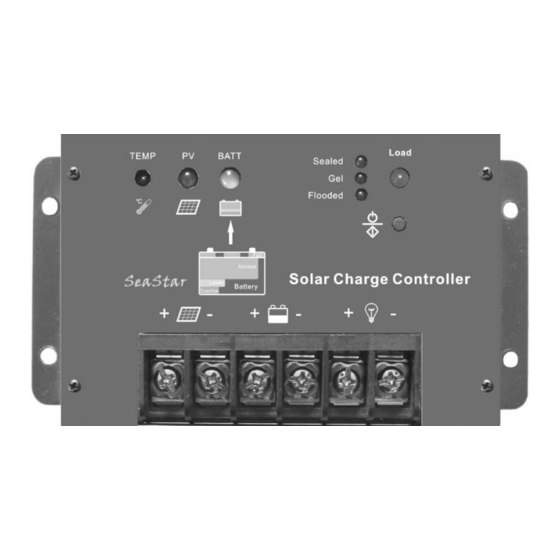
2.2 Product Features Figure 2-1 SeaStar characteristics 1 – Temperature Sensor Measure ambient temperature and make temperature compensation for charging and discharging. – Charging status LED indicator An LED indicator that shows charging status and also indicates when battery voltage is higher than over voltage disconnect voltage. -
Page 7: Installation Instructions
5 – Load status indicator Display the load status. 6 – Setting button Control the load ON / OFF and select the battery type. 7 – Solar Module Terminals Connect solar modules. 8 – Battery Terminals Connect batteries. 9 – Load Terminals Connect loads. -
Page 8: Mounting
3.2 Mounting NOTE: When mounting the controller, ensure free air through the controller heat sink fins. There should be at least 6 inches (150 mm) of clearance above and below the controller to allow for cooling. If mounted in an enclosure, ventilation is highly recommended. WARNING: Risk of explosion! Never install the controller in a sealed enclose with flooded batteries! Do not install in a confined area where battery gassed can accumulate. -
Page 9: Wiring
Step 3: Mark Holes Use a pencil or pen to mark the four (4) mounting hole locations on the mounting surface. Step 4: Drill Holes Remove the controller and drill 4mm holes in the marked locations. Step 5: Secure Controller Place the controller on the surface and align the mounting holes with the drilled holes in step 4. - Page 10 Fuse Battery Figure 3-2 Battery connecting Before battery is connected, make sure that battery voltage is greater than 6V so as to start up the controller. If system is 24V, make sure battery voltage is not less than 18V. System voltage can only be automatically recognized when controller start up for the first time.
- Page 11 Connect the positive (+) and negative (-) of loads to controller load terminals as shown in Figure 3-3. The load terminal may exist voltage, connect carefully to avoid short circuit. An in-line fuse holder should be wired in series in the load positive (+) or negative (-) wire as show in Figure 3-3.
- Page 12 Step 4: Confirm Wiring Double-check the wiring in step1 through 3. Confirm correct polarity at each connection. Verify that all six terminals are tightened. Solar Module Load Fuse Fuse Battery Figure 3-5 System wiring review Step 5: Install Fuse Install a suitable fuse in each fuse holder in the following order: 1.
-
Page 13: Operation
4 Operation 4.1 PWM Technology (Series Pulse Width Modulation) The controller adopts the advanced series pulse width modulation (PWM) charging mode. With range of 0-100%, it can charge the battery quickly and stably under any condition of solar photovoltaic system. PWM charging mode use automatic conversion duty ratio pulses current to charge the battery. - Page 14 ·Boost Charge When the battery has recharged to the Boost voltage setpoint, constant- current regulation is used to prevent heating and excessive battery gassing. The Boost stage remains 120 minutes and then goes to Float Charge. ·Float Charge After the battery is fully charged in Boost voltage stage, the controller reduces the battery voltage to Float voltage set point.
-
Page 15: Led Indicators
NOTE: Equipment damage! Over-charging and excessive gas precipitation may damage the battery plates and activate material shedding on them. Too high an equalizing charge or for too long may cause damage. Please carefully review the specific requirements of the battery used in the system. - Page 16 Charging Status indicator GREEN ON whenever sunlight is available for battery charging, GREEN FAST FLASHING when battery over voltage. Please refer to section 5 for troubleshooting. Charging Status LED indicator Table 4-1 Color Indicator Charging Status Green On Solid Charging Green Fast Flashing...
- Page 17 Load status indicator: When the load current is 1.25times of rated current for 60 seconds, or the load current is 1.5 times of rated current for 5 seconds (overload); or load current is more than 3.5 times of rated current(Short Circuit) ,the load status indictor will be red and flashing. Please refer to section 5 for trouble shooting.
-
Page 18: Setting Operation
Setting Operation Sealed Setting indicator Load Status LED indicator Setting indicator Flooded Setting Indicator Setting button Figure 4-3 Setting operation indicating ·Load Work Mode Setting When the controller is powered on, press the setting button to control the load output. Press the button once, the ON/OFF status will be changed corresponding. -
Page 19: Protection, Troubleshooting And Maintenance
5 Protection, Troubleshooting and Maintenance 5.1 Protection ·PV Array Short Circuit If PV array short circuit occurs, clear it to resume normal operation. ·Load Overload If the load current exceeds the maximum load current rating, the controller will disconnect the load. Overloading must be cleared up through reapply power or pressing the setting button. -
Page 20: Troubleshooting
5.2 Troubleshooting Trouble Shooting Table 5-1 Faults Possible reasons Troubleshooting Charging LED indicator off Check that PV and battery during daytime when sunshine array wire connections falls on PV modules properly. disconnection correct and tight. Green charging LED indicator Battery voltage Check if battery voltage fast flashing... - Page 21 Load status indictor red and Over load or short Overload: reduce the load flashing circuit and press the button once, the controller will resume to work after 3s; Short circuit: when the first short-circuit occurs, the controller will automatically resume to work after 10s;...
-
Page 22: Maintenance
5.3 Maintenance The following inspections and maintenance tasks are recommended at least two times per year for best controller performance. Check that the controller is securely mounted in a clean and dry environment. Check that the air flow and ventilation around the controller is not blocked. Clear all dirt or fragments on the heat sink. -
Page 23: Warranty
6 Warranty The SeaStar charge controller is warranted to be free from defects for a period of Two (2) years from the date of shipment to the original end user. We will, at its option, repair or replace any such defective products. •... -
Page 24: Technical Specifications
7 Technical specifications Electrical Parameters Table 7-1 Description Parameter 12 / 24VDC Nominal System Voltage Auto work Maximum Battery Voltage SS1024 Rated Battery Current SS1524 SS2024 Charge Circuit Voltage Drop ≤0.26V Discharge Circuit Voltage Drop ≤0.15V Self-consumption ≤6mA Temperature Compensation Coefficient Table7-2 Description Parameter... - Page 25 Battery Voltage Parameters (temperature at 25℃) Table 7-3 Charging Parameters Battery charging Sealed Flooded setting Over Voltage 16V; x2/24V 16V; x2/24V 16V; x2/24V Disconnect Voltage Charging Limit 15.5V;x2/24V 15.5V;x2/24V 15.5V;x2/24V Voltage Over Voltage 15V; x2/24V 15V; x2/24V 15V; x2/24V Reconnect Voltage Equalize Charging ------- 14.6V;x2/24V...
- Page 26 Environmental parameters Table 7-4 Environmental parameters Parameter Working temperature -35℃ to +55℃ Storage temperature -35℃to +80℃ SS1024 Mechanical parameters Table 7-5 Mechanical Parameter Parameter Overall dimension 132(5.2)x70.5(2.77)x30(1.18) mm/inches Mounting dimension 122(4.8) x 40(1.57) mm/inches Mounting hole size Φ4.5 Terminal Net weight 0.15kg SS1524 &...
- Page 27 mm(inches) 122(4.8) 132(5.2) Figure1 SS1024 Dimensions 127(5) 137(5.4) Figure2 SS1524 & SS2024 Dimensions...
- Page 28 Westech-Solar Energy GmbH Tel:+49 89 89545770 Fax:+49 89 89545771 E-mail:service@westech-solar.com Website:www.westech-solar.com...
Need help?
Do you have a question about the SeaStar SS1024 and is the answer not in the manual?
Questions and answers