Advertisement
Quick Links
SWITCH
I N D U S T R I A L
Q
I
uick
nstallation
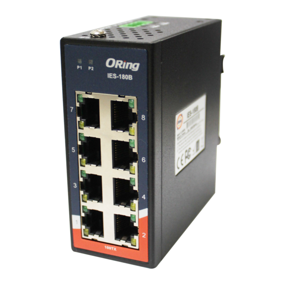
Introduction
The
IES-180B
is a mini type unmanaged Ethernet switch with eight
10/100Base-T(X) ports. With a compact size, the device can be installed
easily without taking up much space. Featuring an IP-30 housing, the
switch can be operated in an operating temperature ranging from -40 C to
o
70 C.
Package Contents
The
IES-180B series
are shipped with the following items. If any of these
items is missing or damaged, please contact your customer service
representative for assistance.
Contents
Pictures
Number
IES-180B
DIN-rail Kit
Wall-mount Kit
QIG
Preparation
Before you begin installing the switch, make sure you have all of the package
contents available.
Safety & Warnings
Elevated Operating Ambient:
If installed in a closed cabinet, the operating
ambient temperature of the rack environment may be greater than room ambient.
Therefore, consideration should be given to installing the equipment in an
environment compatible with the maximum ambient temperature (Tma) specified
by the manufacturer.
Reduced Air Flow:
Installation of the equipment should be such that the
amount of air flow required for safe operation of the equipment is not
compromised.
Mechanical Loading:
Mounting of the equipment in the d
such that a hazardous condition is not achieved due to uneven mechanical
loading.
Circuit Overloading:
Consideration should be given to the connection of the
equipment to the supply circuit and the effect that overloading of the circuits
might have on overcurrent protection and supply wiring. Appropriate
consideration of equipment nameplate ratings should be used when addressing
this concern.
Q I G
IES-180B
G
uide
Dimension (Unit: mm)
o
P1
P2
IES-180B
7
8
5
6
3
4
X 1
1
2
10/100TX
41.0
X 1
X 2
Panel Layouts
X 1
Front Panel
1
2
P1
P2
IES-180B
3
7
4
5
5
3
1
10/100TX
Real Panel
in-rail
should be
1
1907-2-29-IES180B-1.0
IES-180B
22.6
40.0
22.0
28.0
13.1
90.0
41
22.0
14.0
13.5
Top Panel
2
1. PWR1 LED
2. PWR2 LED
3. LAN port
4. LAN port link/act indicator
5. LAN port duplex/Collision
8
indicator
6
1. Wall-mount screw holes
4
2. Terminal block
2
1. Din-rail screw holes
PRINTED ON RECYCLED PAPER
Industrial Unmanaged Switch
Installation
DIN-rail Installation
Step 1:
Slant the switch and screw the Din-rail kit onto the back of the switch, right in the
middle of the back panel.
Step 2:
Slide the switch onto a DIN-rail from the Din-rail kit and make sure the switch clicks into
the rail firmly.
40.0
Wall-mounting
1
Step 1:
Screw the two pieces of wall-mount kits onto both sides of the switch. A
total of eight screws are required, as shown below.
Step 2:
Use the switch, with wall mount plates attached, as a guide to mark the correct
locations of
wall-mount
screws.
Step 3:
Insert screw through the large parts of the keyhole-shaped apertures, and then slide
the switch downwards. Tighten the four screws for added stability.
Version 1.0
P1
P2
IES-180B
7
8
5
6
3
4
1
2
10/100TX
Quick Installation Guide
Advertisement

Related Manuals for ORiNG IES-180B


Summary of Contents for ORiNG IES-180B
- Page 1 -40 C to the rail firmly. 70 C. 90.0 Package Contents IES-180B series are shipped with the following items. If any of these 22.0 items is missing or damaged, please contact your customer service representative for assistance.
- Page 2 -40 to 70 C (-40 to 158 F) Configurations Operating Humidity 5% to 95% Non-condensing Regulatory Approvals After installing the IES-180B and connecting cables, start the switch by turning on power. The green power LEDs should turn on. FCC Part 15, CISPR (EN55022) class A EN61000-4-2 (ESD),...
Need help?
Do you have a question about the IES-180B and is the answer not in the manual?
Questions and answers