Table of Contents
Advertisement
Quick Links
STS-5SU Internal Stacker Unit
Introduction
The SmartStack STS-5SU Internal Stacker Unit is a 4-port
interface module that is installed into the rear slot of any
SmartStack Token Ring Switch. When five SmartStack
switches are connected together through the SmartStack STS-
5SU module, the switches combine to form one logical switch.
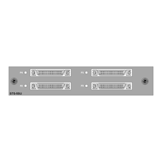
The SmartStack STS-5SU front panel is shown in Figure 1.
Figure 1. SmartStack STS-5SU Front Panel
SmartStack STS-5SU Package Contents
The SmartStack STS-5SU package contains the following
items:
•
One SmartStack STS-5SU Internal Stacker Unit for the
Cabletron SmartStack Token Ring Switch
•
One SmartStack STS-5SU Installation Guide (this
document)
Installation
Use the following steps when installing the SmartStack STS-
5SU module in the SmartStack switch.
Note: SmartStack STS-5SU modules are not hot-swappable.
Always be sure that the power is off before installing or
removing a module. If the power is on, damage to the
equipment may result. Once the module is installed in the
switch, external cables may be connected or removed without
having to remove power from the switch.
1. Disconnect power to the switch.
2. If a blank cover is over the stacker slot on the back panel,
remove it by unscrewing the two attachment screws.
3. To prevent possible static damage to the module, hold it by
its edges only. Be careful not to touch the top or bottom.
4. Slide the module into the slot evenly, taking care to line up
the edges with the guides.
5. Seat the module by pressing the front of the module with
your thumbs.
6. Secure the module to the chassis by tightening the thumb
(panel) screws at the left and right edges of the front panel.
Do not overtighten the screws.
7. Return power to the switch.
SmartStack STS-5SU Connectors and LEDs
The following tables describe the connectors and LEDs on the
SmartStack STS-5SU front panel.
Connector
P2–P5
50-pin SCSI-2 connector for proprietary
Stacker Link cable.
Table 1. SmartStack STS-5SU Network Connector
LED
State
P2–P5
Off
No connection has been established.
On
A connection has been established.
Table 2. SmartStack STS-5SU LINK LEDs
Connecting the Stacker Link Cable
A proprietary 50-pin cable must be used to connect ports on
the SmartStack STS-5SU module with up to four SmartStack
STS-LM Link Modules in other SmartStack switches. Five
switches can be combined in this way to form a very cost-
effective stack of switches.
Note: The SmartStack STS-5SU Internal Stacker Unit must
only be connected to SmartStack STS-LM Link Modules. You
cannot create a stack by connecting SmartStack STS-5SU
modules together.
When inserting the cable connector, keep the connector
straight to minimize the risk of bent or damaged pins.
1
Working With a Stack
When the SmartStack switch powers up, it runs through a
series of diagnostics. Immediately after the diagnostics are
complete, the SmartStack switch enters the stack discovery
mode. The discovery mode is used to sense if the unit is cabled
to other units. If the SmartStack switch through a SmartStack
STS-5SU is connected to other units during the discovery
mode, the switches automatically combine to form a stack.
Each unit is assigned a box number. The switch with the lower
MAC address becomes Box 1, the switch with the higher
MAC address becomes Box 2 and so forth. When accessing
switch specific settings from a management console, you will
be prompted for a box number.
Description
The switches in the stack combine certain configuration
parameters so that the stack as a unit uses one set of
parameters. These parameters are discussed below in "Inter-
Box Parameters".
The stack can now be managed as a single entity from a
management console or management application.
Description
Inter-Box Parameters
The SmartStack switches participating in the stack must
combine configuration information so that the stack as a whole
uses common parameters. One of the participating switches
becomes the provider of inter-box parameters.
If the switches have the same configuration information, the
switch that becomes Box 1 becomes the provider. If the
configuration information is different, a split-stack will be
formed and a warning message will be displayed on the
console screen. You will be requested to briefly press the
SysReq button on the switch that is to be the provider of inter-
box parameters. When you have selected the provider, the
other switch will replace its stack related configuration
parameters with those of the provider.
Table 3 lists the inter-box parameters.
2
3
Advertisement
Table of Contents

Related Manuals for Cabletron Systems STS-5SU


Summary of Contents for Cabletron Systems STS-5SU
- Page 1 SmartStack Token Ring Switch. When five SmartStack switches are connected together through the SmartStack STS- 5SU module, the switches combine to form one logical switch. The SmartStack STS-5SU front panel is shown in Figure 1. Figure 1. SmartStack STS-5SU Front Panel SmartStack STS-5SU Package Contents...
- Page 2 SmartStack STS-5SU port along with the switch ports and that there are no error messages. The SmartStack STS-5SU port will be listed as port If, after installation, there is poor system performance or the SmartStack STS-5SU module does not work at all, remove the module and check for any damaged or bent connector pins.
Need help?
Do you have a question about the STS-5SU and is the answer not in the manual?
Questions and answers