Table of Contents
Advertisement
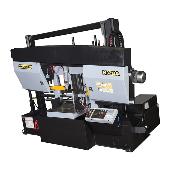
H28A-120
393074
THANK YOU,
On behalf of everyone at HYD·MECH Group Limited, we would like to thank and congratulate you on your decision to
purchase a HYD·MECH bandsaw.
Your new machine is now ready to play a key role in increasing the efficiency of your operation, helping you to reduce cost
while boosting quality and productivity.
To ensure you are maximizing the power and versatility of your new HYD·MECH bandsaw, please take the time to
familiarize yourself and your employees with the correct operation and maintenance procedures as outlined in this
manual. Please keep this instruction manual for future reference in a known location and easily accessible to all users of
the device.
HYD·MECH offers a great variety of options, components, and features for its various models. Therefore, some of the
equipment described in this manual (various illustrations and drawings) may not be applicable to your particular machine.
The information and specifications provided in this manual were accurate at the time of printing. HYD·MECH reserves the
right to discontinue or change specifications or design at any time without notice and without incurring any obligation.
Thank you.
Hyd·Mech Group Limited
P.O. Box 1659, 1079 Parkinson Road
Woodstock, Ontario, N4S 0A9
Phone : (519) 539-6341
Service : 1-877-237-0914
Sales : 1-877-276-SAWS (7297)
Fax : (519) 539-5126
e-mail : info@hydmech.com
Printed SEPT 2017
1
Advertisement
Table of Contents
Troubleshooting

Related Manuals for Hyd-Mech H28A-120


Summary of Contents for Hyd-Mech H28A-120
- Page 1 H28A-120 393074 THANK YOU, On behalf of everyone at HYD·MECH Group Limited, we would like to thank and congratulate you on your decision to purchase a HYD·MECH bandsaw. Your new machine is now ready to play a key role in increasing the efficiency of your operation, helping you to reduce cost while boosting quality and productivity.
-
Page 3: Table Of Contents
TABLE OF CONTENTS SECTION 0 - SAFETY INSTRUCTIONS SUMMARY ............................0.1 BASIC RULES ..........................0.3 RESPONSIBILITIES OF THE OWNER ....................0.3 RESPONSIBILITIES OF THE OPERATOR AND MAINTENANCE PERSONNEL ......0.4 SAFETY HAZARD LABELS ......................0.6 SECTION 1 - INSTALLATION SAFETY PRECAUTIONS .........................1.1 FOUNDATION, LEVELLING AND ANCHORING ................1.2 BARFEED INSTALLATION ......................1.3 CABLE TRAY COVERS ........................1.6 ELECTRICAL CONNECTIONS ......................1.7... - Page 4 SECTION 7 - OPTIONS OPTIONAL ASSEMBLY DRAWINGS: SEE PDF ON ATTACHED CD ..........7.1 BLADE DEVIATION MONITOR ......................7.2 FLOOD MIST SELECTION ......................7.9 SECTION 8 - SPECIFICATIONS H28A-120 SPECIFICATIONS ......................8.1 H28A-120 BANDSAW LAYOUT .......................8.2 H28A-120 BANDSAW LAYOUT .......................8.3 SECTION 9 - WARRANTY WARRANTY .............................9.1...
-
Page 5: Summary
SECTION 0 - SAFETY INSTRUCTIONS SUMMARY All persons operating this machine must have read and understood all of the following sections of this Manual: Section 0 SAFETY Section 2 OPERATING INSTRUCTIONS However, as a memory aid, the following is a summary of the Safety Section. Put Safety First Mandatory Information –... - Page 6 FOREWORD Put Safety First! This Safety Section contains important information to help you work safely with your machine and describes the dangers inherent to bandsaws. Some of these dangers are obvious, while others are less evident. It really is important to PUT SAFETY FIRST. Make it a habit to consider the hazards associated with any action BEFORE you do it.
-
Page 7: Basic Rules
Manual, and When all operations and procedures are in compliance with this Manual. Hyd-Mech Group cannot accept any liability for personal injury or property damage due to operator errors or non-compliance with the Safety and Operating Instructions contained in this Manual. -
Page 8: Responsibilities Of The Operator And Maintenance Personnel
Define responsibilities Clearly define exactly who is responsible for operating, setting-up, servicing and repairing the machine. Define the responsibilities of the machine operator and authorize him to refuse any instructions by third parties if they run contrary to the machine’s safety. Persons being trained on the machine may only work on or with the machine under the constant supervision of an experienced operator. - Page 9 Clothing, jewelry, protective equipment Personnel operating or working on the machine must not wear unrestrained long hair, loose-fitting clothes and dangling jewelry. When operating or working on the machine, always wear suitable, officially tested personal protective equipment such as safety glasses and safety boots and any other equipment required by workplace regulations.
-
Page 10: Safety Hazard Labels
On Hyd-Mech machines the Master Disconnect Switch will be of one of four types: • Rotary switch mounted in electrical control cabinet door and inter-locked with door. - Page 11 MOVING BANDSAW BLADE WILL CUT Do NOT operate with guard removed. Do NOT place hands or fingers near moving bandsaw blade. For blade changing, always follow the proper Blade Changing Procedure, as given in Section 3 of this manual. PINCH POINT Machine parts may move without warning, either because the machine is operating automatically, or because another person initiates the motion.
- Page 12 Item # 391938 Item # 391335...
- Page 13 Item # 391340 Idler Guide Arm Drive Guide Arm Item # 391937...
- Page 14 Fixed Vise Shuttle Vise Item #. 392801 0.10...
-
Page 15: Section 1 - Installation
• HOLD WORK PIECE FIRMLY AGAINST TABLE. • DO NOT REMOVE JAMMED CUTOFF PIECES UNTIL BLADE HAS STOPPED. NO MODIFICATIONS TO THE MACHINE ARE PERMITTED WITHOUT PRIOR APPROVAL FROM HYD-MECH. ANY APPROVED MODIFICATIONS SHOULD ONLY BE UNDERTAKEN BY TRAINED PERSONNEL. -
Page 16: Foundation, Levelling And Anchoring
FOUNDATION, LEVELLING AND ANCHORING The machine location should be carefully selected. A flat concrete floor area should be chosen. It should have enough free space surrounding the machine to enable free access for safe operation and maintenance. The machine must be leveled in both directions i.e. along and across its in-feed conveyor especially when machine is to be inserted into a larger conveyor system. -
Page 17: Barfeed Installation
BARFEED INSTALLATION The H28A 120 machine is calibrated, adjusted, leveled, and inspected in the factory before shipping. The machine is partially disassembled for shipping purposes. The two main parts of the machine are the front section and the conveyor section. The installation consists of the following sections: 1. - Page 18 2 Bolts As mentioned earlier, the conveyor should be leveled in both directions (page 1.2); across and along the infeed conveyor. Six leveling screws are provided, three down each length of the conveyor. Steel plates are to be placed under each screw to prevent their sinking into the concrete floor.
- Page 19 To safely ship the conveyor, weldments and brackets are added to secure the conveyor to its base and to prevent the shuttle from moving. Once the conveyor has been leveled to the bandsaw, remove supports. A shuttle support bracket must be removed in-order for the shuttle to move. The bracket is located on the same side as the shuttle gearmotor assembly.
-
Page 20: Cable Tray Covers
CABLE TRAY COVERS Remove the three cable covers that line the barfeed table. Unpack and unravel the cable track holding the wires and hoses for the barfeed shuttle. Once all cables/hoses have been connected, re-install cable tray covers and bolts. Fasten the two brackets that will hold the cable track in place. -
Page 21: Electrical Connections
ELECTRICAL CONNECTIONS Connect both cables to the electric motor as shown. Connect the cables for the limit switches as shown in the picture below. CABLE #17 (TOP) CABLE #19 (MIDDLE) CABLE #18 (BOTTOM) -
Page 22: Hydraulic Connections
HYDRAULIC CONNECTIONS SHUTTLE VISE HOSE CONNECTIONS Remove cover located towards the top of the shuttle frame. Feed hoses 21L and 22E up through the column and attach as shown. Re-Install the cover when finished. Line 21L Line 22E... - Page 23 The following hydraulic junction block is located on the drive side shuttle vise frame. Connect hose 21 and 22 as shown. Line 22 Line 21 Cable tie the bundle of hoses/cables to the gearbox as shown below.
-
Page 24: Squaring Vise (Option) Hose Connections
SQUARING VISE (OPTION) HOSE CONNECTIONS Feed hose 82E up through the column and attach as shown. Attach hoses 81 and 82 as shown. Line 81 Line 82 Line 82E 1.10... -
Page 25: Machine Guard Installation
MACHINE GUARD INSTALLATION Position the three pieces of the safety guard around the conveyor. The idler side guard is connected to the machine column and the drive side is connected to the control box. The rear guard is connected to the conveyor and to the two sides with a bracket. - Page 26 Fasten the trip wire control box to the safety guard and complete the wire connections (see schematics). The box is attached to the mounting plate with four socket head cap screws. The plate is mounted to the safety guard with two hex bolts.
-
Page 27: Wiring Connections
WIRING CONNECTIONS After the machine is leveled and anchored the necessary power hook-up needs to be performed. In order to provide safe operation as well as to prevent potential damage to the machine, only qualified personnel should make the connections. BEFORE START-UP THE FOLLOWING TWO POINTS SHOULD BE CHECKED: 1. -
Page 28: Earth Grounding Procedure
EARTH GROUNDING PROCEDURE The customer is to provide and install a ground rod approximately .60 (15mm) diameter, copper clad steel, to be driven no less than 8’ (2.5m) into the ground, no more than 10’ (3m) away from control enclosure. The ground rod is to be connected to customer’s in plant ground system. -
Page 29: Section 2 - Operating Instructions
SECTION 2 - OPERATING INSTRUCTIONS This section has been prepared to give the operator the ability to set up the saw for most cutting situations. Before cutting any material, the operator should be familiar with all operations and controls as well as the basic cutting theory described below. -
Page 30: Plc 100 Control System
PLC 100 CONTROL SYSTEM OPERATION OVERVIEW The PLC is a programmable logic controller that allows the operator to run the machine in both manual and automatic modes. All of the machine functions are also controlled from the PLC operator interface. There are four function buttons on either side and eight function buttons below the display. - Page 31 NOTE: If an emergency situation arises during any operation, use the large red mushroom EMERGENCY STOP button located on the control panel to shut down the machine. The PLC operator interface is used in all four operating modes: 1. Manual Mode – permits the operator to control all machine functions using the pushbuttons, as well as the operator interface function keys.
-
Page 32: Manual Mode
SERVICE MODE The SERVICE MODE allows the user to adjust the various PLC parameters. The user will be prompted for a password. Contact Hyd-Mech Group Limited to access this mode. MANUAL MODE Pressing this key will put the saw in MANUAL MODE. - Page 33 PLC Operator Interface and Labeled Buttons MANUAL MODE MANUAL MODE is the default mode. All functions are enabled when in MANUAL MODE. The screen will look as follows:...
-
Page 34: Single Cut Mode Operation
SINGLE CUT MODE OPERATION In MANUAL mode, the PLC allows the operator to initiate a SINGLE CUT MODE to cut one piece at a desired length. Closing the front vise automatically initiates Single Cut Mode. Follow the procedure below. 1. A trim cut should be made before initiating the SINGLE CUT MODE operation 2. -
Page 35: Automatic Operation
AUTOMATIC OPERATION To enter AUTO MODE, the FIXED VISE must be closed, putting the saw in SINGLE CUT MODE. When the AUTO MODE key is pressed, the red indicator will come on. The screen will change to the JOB display window as shown below and will be ready for editing or starting a new job. -
Page 36: Working With A Queue
WORKING WITH A QUEUE The purpose of a QUEUE is to allow the operator to run several jobs (maximum of 5) in series if they are of the same material and shape. To run a QUEUE, it is necessary to program in all job values as is done with programming a single job. After the jobs are programmed in, press QUEUE, press CLEAR to clear the QUEUE, and enter the desired JOB #’s in the desired sequence. -
Page 37: Parameters
PARAMETERS The parameters can be accessed by pressing the ser- vice mode button on the panel. These parameters can be changed without a password. COOLANT SELECTION In Auto Mode press the NEXT (coolant) button to move to AUTO MODE - 2. Use the FLODD/MIST button to select the different type of coolant. - Page 38 PARAMETER DEFINITION Blade Speed Display adjustment number. If actual blade speed is different than SPEED CONSTANT displayed blade speed, a new Speed Constant will need to be calculated. Speed Constant = old Speed Constant x actual speed / displayed speed. Feed rate display constant value.
-
Page 39: Hydraulic Feed Control
HYDRAULIC FEED CONTROL The Hydraulic Feed Control is located to the left of the control panel. These controls allow independent control of Feed Force (FF) and Feed Rate (FR) FEED FORCE KNOB Used to set feed force limit (counterclockwise rotation to increase and clockwise rotation to decrease). -
Page 40: Cutting Parameters Chart
CUTTING PARAMETERS CHART A full size CUTTING PARAMETERS CHART is mounted on the front of the saw. The chart contains five steps for the operator to follow in order to achieve optimum performance of the saw. These steps are detailed on the following pages. Saw Cutting Parameters Chart CHART EXAMPLE #1 We will use the parameters chart to set up the saw for cutting 8”... - Page 41 STEP 2: SET FEED FORCE LIMIT The Feed Force Limit is the maximum amount of force with which the head is allowed to push the blade into the work-piece. CUTTING SOLIDS For cutting solids, the wider the section, the less FF should be set, to avoid blade overloading. See the graph below. % OF FF SETTING (INDICATED...
- Page 42 STEP 3: DETERMINE OPTIMUM BLADE PITCH - TEETH PER INCH (T.P.I.) Selecting a blade with proper tooth pitch is important in order to achieve optimal cutting rates and good blade life. For cutting narrow or thin wall structural materials a fine blade with many teeth per inch (T.P.I.) is recommended. For wide materials a blade with a coarse pitch should be used.
- Page 43 STEP 4: DETERMINE OPTIMUM BLADE SPEED, V (ft/min) (m/min) The relationship between optimum blade speed and effective material width for various materials is represented on the graph shown. The graph shows that as effective material width gets wider or as material gets harder, lower blade speeds are recom- mended.
- Page 44 The following table gives examples of the optimum blade speeds for different materials. MATERIALS OPTIMUM BLADE SPEED (ft/min) (m/min) 5” (125mm) Diameter Solid Carbon Steel 12” (300mm) I-Beam 4” x 4” (100mm x 100mm) Rect. Tube 1/4” (6mm) Wall 4” (100mm) 400 Stainless Steel 2”...
- Page 45 FEED RATE, continued If the saw is fitted with a blade coarser than optimum (e.g.: 1.4/2.5 TPI) we can still use the graph, but we go to the 1.4/2.5 curve. As a result we find that the FEED RATE is decreased to 1.3 in/min (133mm/min) for this blade. If however, the machine is fitted with a finer than optimum blade (e.g.
-
Page 46: Additional Controls
ADDITIONAL CUTTING SETUP EXAMPLES, continued EXAMPLE # 3 Material: Bundle low carbon steel 2” x 2” Tube with 1/4” wall, 12 piece bundle (50mm x 50mm with 6mm wall) Dimensions: 6” x 8” (150mm x 200mm) Effective Material Width: 5” ( .6 X 8” ) 120mm (.6 x 200) Step 1 Feed Force limit setting for 8”... -
Page 47: Head Up And Down Limit Setting
HEAD UP AND DOWN LIMIT SETTING The head up limit is used to restrict the distance the head travels for each stroke. It can be adjusted at any time by moving the switch trip plate to any position on the vertical bar. The trip plate & switches are found behind the head on the drive end near the gear box. -
Page 48: Bundling Operation (Option)
BUNDLING OPERATION (OPTION) The bundling vises can be operated in direct conjunction with the front and shuttle vises or at a slower clamping speed. Either bundling can be turned on or off at any time. The on / off valves are shown in the photos. The speed at which the bundling jaws open and close can be adjusted as required by turning the flow control valve for each bundling cylinder. -
Page 49: Section 3 - Maintenance And Troubleshooting
SECTION 3 – MAINTENANCE AND TROUBLESHOOTING LOCK-OUT “Lock-out”, or “Lock-out Tag-out” are terms that refer to procedures taken to prevent the unexpected start-up, or other re- lease of energy, by a machine, whenever anyone is required to remove or bypass safety guards or devices, or whenever anyone is required to place part of his body in a hazard area. -
Page 50: Blade Change Mode Procedure
BLADE CHANGE MODE PROCEDURE Wear safety glasses, gloves, and a long sleeve shirt for protection when handling band saw blades during blade change. NOTE THAT GLOVES SHOULD NEVER BE WORN NEAR A RUNNING BANDSAW BLADE. When handling new blades, or ones that will be re-used, it is important to keep the teeth out of contact with concrete floors. This machine is equipped with hydraulic blade tension and a ‘Blade Change Mode’... -
Page 51: Blade Brush Adjustment
The brush should be replaced as it becomes worn to approximately 70% of its origi- nal 3” diameter. Replacements can be purchased through your Hyd-Mech Group Limited dealer. BLADE TRACKING ADJUSTMENT Blade tracking is set so the teeth of the blade protrude .340”... -
Page 52: Idler Wheel Tracking
IDLER WHEEL TRACKING Release blade tension before adjusting. Adjust tracking by regulating “push” set screws and “pull” bolts. Loosening bolts “A” and turning in set screws “C” by equal amounts will move the blade OFF the wheel. Loosening bolts “B” and turning in set screws “D”... -
Page 53: Gearbox Lubrication (H28A With A603 Gearbox)
GEARBOX LUBRICATION (H28A WITH A603 GEARBOX) The H28A-120 with the A603 gearbox requires 15 litres (3.96 US gallons) of Mobil SHC 634 synthetic oil.. This oil has an ISO Viscosity Grade of 220 that is optimum for ambient temperatures from 20-40 Deg C [70-104 Deg F]. If the machine will be operated for prolonged periods at ambient temperatures below 20 Deg C [70 Deg F] an oil of ISO Viscosity Grade 150 should be substituted. -
Page 54: Output Shaft Lubrication
OUTPUT SHAFT LUBRICATION Always follow Lock-out Procedures before performing this lubrication. Band tension load is carried by a grease lubricated spherical bearing. A grease fit- ting is accessible through the spokes of the blade wheel, as shown at point G in the accompanying illustration. -
Page 55: Lubrication
LUBRICATION The design of the saw is intended to minimize maintenance, although periodically certain moving parts do require lubrica- tion. We recommend that this periodic lubrication be done once a month using any general-purpose grease. In addition to the grease points shown, vise jaw guides, infeed rollers and bundling assemblies require greasing. Shuttle Shaft Bearing Housings Idler Wheel Slider Assembly Grease Nipple... -
Page 56: Hydraulic Maintenance
HYDRAULIC MAINTENANCE There are only FIVE items of routine maintenance associated with the hydraulic system: 1. OIL FILTER – Ten-micron filtration of the hydraulic oil is provided by a spin-on type filter mounted on the tank return line. The element should be changed after the first 50 Hours of operation and then every 500 working hours. Suitable replace- ment elements are: CANFLO RSE-30-10... - Page 57 PROBLEM PROBABLE CAUSE SOLUTION Blade worn. Replace blade. Low blade tension. Tension blade. Saw is cutting out of square vertically. Blade guides. Check for worn guides. Excessive feed rate. Reduce. Saw is cutting out of Stock not square in vises. Adjust accordingly.
- Page 58 PROBLEM PROBABLE CAUSE SOLUTION Reload with stock or reset the blade. Hold Saw starts but will not run On machines so equipped, the out-of- the hydraulic start button and release the after Start button has been stock or blade breakage limit switch blade tension or open vises far enough to released.
-
Page 59: Programmable Logic Control
PROGRAMMABLE LOGIC CONTROL Note: The PLC is equipped with a lithium battery to keep the program stored while the power is shut down. The battery will need to be replaced every 3 to 5 years, depending on the usage. A visual warning will be displayed on the interface when the battery drains to a certain level. -
Page 60: Plc Parameters
PLC PARAMETERS SPEED CONST Blade speed adjustment number. If the actual blade speed is different than the displayed blade speed, a new speed factor will need to be calculated (providing the WHEEL TRGETS parameter is set correctly). Actual speed ÷ display + adjustment factor X existing speed factor = New Speed Factor WHEEL TRGETS Number of targets per revolution of the idler wheel. - Page 61 FEED RATE Activates feed rate display. (Not active on S20A, S23A and H10 machines) ACTUAL POSITION If this value is set to “YES,” displays shuttle vise actual position. HOLD SHT HOME Hold shuttle VISE home and closed during cut. BRKN PROX Allows user to override signal from proximity sensor in case it is broken.
-
Page 62: Plc Troubleshooting
PLC TROUBLESHOOTING Problem 1 (for automatic models with a shuttle) PLC is not measuring lengths Possible causes: 1. Encoder a. Pinion gear is loose on the encoder shaft b. A bad encoder 2. Encoder Cable a. Bad connections at the encoder or the PLC b. - Page 63 Problem 2 (for automatic models with a shuttle) Inaccurate Lengths in Auto Mode Possible Causes: 1. Encoder a. Pinion not engaging the rack all the way from front to back. b. Mechanical interference. c. Pinion loose on the encoder shaft. 2.
- Page 64 If the display does not read as specified: - Check the encoder pinion gear to be sure it can run smoothly down the rack and that the gear and rack teeth engage over the entire travel of the shuttle. - Check that the pinion gear is tight on the encoder shaft. - Check the encoders cable connections, a loose connection could easily cause this concern.
- Page 65 GENERAL RULE: Lowering the parameter value = longer shuttle travel = longer parts Increasing the value = shorter shuttle travel = shorter parts Problem 3 (for P Models, disregard all references to a shuttle) Auto Cycle Not Being Completed In auto mode, the PLC controls the saw functions through output relays. For a certain function to be actuated, the PLC must first see specific input(s).
- Page 66 As mentioned, beside each input and output terminal there is a bank of red LED’s. Each light corresponds to an input or output. An input LED will light when it’s specific input signal is being received at the PLC and output LED’s will light when the PLC commands specific outputs.
-
Page 67: Mitsubishi Plc Inputs And Outputs
MITSUBISHI PLC INPUTS AND OUTPUTS Input and output terminal identification: The top row of identification labels corresponds to the top row of terminals and the bottom row of labels to the bottom row of terminals. Input and output LED numbers correspond to the input or output of the same number. I.E. input LED #0 cor- responds to input X0. -
Page 68: M12 Pin Assignments For M12 I/P & O/P Devices
FX3U-48MR-ES INPUTS OUTPUTS Shuttle Encoder, Channel A COM1 Fused 120Vac Supply Shuttle Encoder, Channel B Hydraulic Pump Start Blade Speed or Proximity Switch NOT USED Feed rate encoder A / Angle Encoder A NOT USED Feed rate encoder B / Angle Encoder B Blade Pilot Light &... - Page 69 LENGTH CALIBRATION PROCEDURE Prior to initiating the calibration procedures the following steps are to be taken: 1. The saw must not be in METRIC units. 2. Clear all jobs in the Queue. 3. All “optional” PLC parameters below must be inactive (See page 3.11) a.
- Page 70 To adjust “ACTUAL LGTH” value The Length Calibration Procedure MUST be performed. This may be done with material in the machine (cut and measure material length) or with no material in the machine (let machine complete the calibration cycle, then enter new value). If part length error gets longer as the programmed length increases;...
- Page 71 NOTE: To determine if the encoder channels are connected, observe the actual height value parameter for the sign during head up movement while in calibration mode. If the actual height value shows as a negative number, the channels must be reversed and the calibration procedure repeated.
-
Page 72: Section 4 - Electrical
SECTION 4 - ELECTRICAL ELECTRICAL SCHEMATICS: SEE PDF ON ATTACHED CD... -
Page 73: Section 5 - Hydraulic
SECTION 5 - HYDRAULIC HYDRAULIC SCHEMATICS & PLUMBING DIAGRAMS: SEE PDF ON ATTACHED CD... -
Page 74: Section 6 - Mechanical Assemblies
SECTION 6 - MECHANICAL ASSEMBLIES MECHANICAL ASSEMBLY DRAWINGS & PARTS LIST: SEE PDF ON ATTACHED CD... -
Page 75: Section 7 - Options
SECTION 7 - OPTIONS OPTIONAL ASSEMBLY DRAWINGS: SEE PDF ON ATTACHED CD... -
Page 76: Blade Deviation Monitor
BLADE DEVIATION MONITOR This system monitors lateral blade deviation during cutting. If the blade deflection increases beyond the pre-set warning limit, then the monitoring device sends a warning signal by means of a flashing beacon mounted on top of the machine head. If no steps are taken to correct this condition, the machine will continue to cut until the pre-set shut-down limit is reached. - Page 77 Warning and shutdown limits adjustments To adjust the warning and shutdown limits, enter the MONITOR LIMIT SETTING screen by pressing function key F2 labeled Blade Devi. LmtSet . Navigation Keys Enter Key Figure 1 Operator interface panel. The MONITOR LIMIT SETTING screen will be displayed (Figure 2). There are two scales, the upper one showing the preset right and left warning limits, and the lower scale showing the preset right and left shutdown limits.
- Page 78 Cut out warning limit – (out - cutting towards outfeed, range 0 ~100) This parameter will adjust the warning limit if the blade is cutting towards the part. Increasing this value decreases sensitivity, which will result in a warning further away from nominal straight. Cut in warning limit –...
- Page 79 Figure 4. Parameter settings screen. To set any of the numerical parameters, use the NAVIGATION keys (Figure 1) to place the cursor over the number. Key in the desired value, and then press ENTER. To change the ON/OFF parameters, place the cursor over the parameter, and press ENTER to toggle between ON and OFF.
- Page 80 To return from the PARAMETER screen to the AUTO or MANUAL screens, press the RETURN (F8 function key, then F7 Figure 1). To access the HISTOGRAM screen (Figure 6), press HSTGRM (F2 function key). To return from the HISTOGRAM screen to the AUTO or MANUAL screens, press Ret (F2 function key) and then press the RETURN (F8 then F7 function keys).
- Page 81 Current deflection Cut in warning limit Cut out warning limit Cut out maximum limit Cut in maximum limit Figure 8 Auto Mode screen. SENSOR ADJUSTMENT PROCEDURE It is desirable for the un-deflected position of the blade to lie in the center of the sensing range of the proximity transducer.
- Page 82 d. Confirm that correct manual motor starter has been turned off by starting hydraulics e. Wait 1 minute and then attempt to start the blade motor. If the blade motor does not start proceed to step 2. 2. Position the guide arm at mid point of the range between fully open and fully closed. 3.
-
Page 83: Flood Mist Selection
FLOOD MIST SELECTION 1. Selecting FLOOD or MIST coolant 2. In Auto Mode press NEXT (coolant) button to move to AUTO MODE ‐ 2 3. Use FLOOD/MIST button to select different type of coolant. 4. Use RETURN button to return to previous screen ... -
Page 84: Section 8 - Specifications
SECTION 8 - SPECIFICATIONS H28A-120 SPECIFICATIONS H28A-120 BANDSAW SPECIFICATIONS Round 28" (711mm) Capacity Rectangular 28" (711mm) wide x 28" (711mm) high 6 Cant 24" x 28" (H x W) Length 25'-0" (7620mm) Blade Width 2" (51mm) Thickness .063" (1.6mm) Blade Tension... -
Page 85: H28A-120 Bandsaw Layout
H28A-120 BANDSAW LAYOUT... - Page 86 H28A-120 BANDSAW LAYOUT...
-
Page 87: Section 9 - Warranty
ORAL, INCLUDING WITHOUT LIMITATION ANY IMPLIED WARRANTIES OF MERCHANTABILITY OR FITNESS FOR A PARTICULAR PURPOSE. This warranty may not be changed, altered, or modified in any way except in writing by Hyd-Mech Group Limited HYD·MECH GROUP LIMITED 1079 Parkinson Road P.O.
Need help?
Do you have a question about the H28A-120 and is the answer not in the manual?
Questions and answers