Hyd-Mech H14A Manual
Hide thumbs
Also See for H14A:
- Safety and operating instructions manual (67 pages) ,
- Manual (116 pages)
Table of Contents
Advertisement
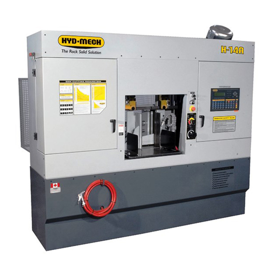
H14A
2012
817531
Thank you,
On behalf of everyone at HYD·MECH Group Limited, I would like to thank and congratulate you on your decision to
purchase a HYD·MECH bandsaw.
Your new machine is now ready to play a key role in increasing the efficiency of your operation, helping you to reduce
cost while boosting quality and productivity.
To ensure you are maximizing the power and versatility of your new HYD·MECH bandsaw, please take the time to
familiarize yourself and your employees with the correct operation and maintenance procedures as outlined in this
manual.
We sincerely appreciate the confidence you have demonstrated in purchasing our product and look forward to building
a long and mutually beneficial relationship.
Thank you
Hyd·Mech Group Limited
P.O. Box 1659, 1079 Parkinson Road
Woodstock, Ontario, N4S 0A9
Phone : (519) 539-6341
Service : 1-877-237-0914
Sales : 1-877-276-SAWS (7297)
Fax : (519) 539-5126
info@hydmech.com
e-mail :
1
Advertisement
Table of Contents
Troubleshooting

Related Manuals for Hyd-Mech H14A


Summary of Contents for Hyd-Mech H14A
- Page 1 H14A 2012 817531 Thank you, On behalf of everyone at HYD·MECH Group Limited, I would like to thank and congratulate you on your decision to purchase a HYD·MECH bandsaw. Your new machine is now ready to play a key role in increasing the efficiency of your operation, helping you to reduce cost while boosting quality and productivity.
-
Page 3: Table Of Contents
DRIVE WHEEL TRACKING (Refer to gearbox illustration) ..............3.4 IDLER WHEEL ADJUSTMENT ......................3.4 BLADE GUIDE ADJUSTMENT ......................3.5 BLADE BRUSH ADJUSTMENT .......................3.5 LUBRICATION ..........................3.5 GEARBOX LUBRICATION (H14A WITH A412 GEARBOX) ............3.7 TROUBLE SHOOTING GUIDE ......................3.7 TROUBLESHOOTING THE H14A ....................3.8 PROGRAMMABLE LOGIC CONTROL (2100 V2.7 SOFTWARE) ..........3.11... - Page 4 VISE and BUNDLING CLAMP SPEED ADJUSTMENT ..............7.1 VARIABLE VISE PRESSURE KNOB ....................7.1 FOR OPTIONAL ASSEMBLY DRAWINGS SEE PDF ON ATTACHED CD ........7.1 OUT OF STOCK LIMIT SWITCH .....................7.2 MIST COOLANT SYSTEM .......................7.2 seCTIOn 8 - sPeCIfICATIOns H14A LAYOUT ..........................8.2 seCTIOn 9 - WARRAnTY WARRANTY .............................9.1...
-
Page 5: Summary
seCTIOn 0 - sAfeTY InsTRUCTIOns sUMMARY All persons operating this machine must have read and understood all of the following sections of this Manual: Section 0 SAFETY Section 2 OPERATING INSTRUCTIONS However, as a memory aid, the following is a summary of the Safety Section. Put safety first Mandatory Information –... - Page 6 fOReWORD Put safety first! This Safety Section contains important information to help you work safely with your machine and describes the dangers inherent in our machines. Some of these dangers are obvious, while others are less evident. It really is important to PUT SAFETY FIRST. Make it a habit to consider the hazards associated with any action BEFORE you do it.
- Page 7 signatures Everyone involved in operation of this machine must sign below to confirm that: I have read and understood all parts of Section 0 – Safety, and Section 2 – Operating Instructions. name Date signature Everyone involved in the installation, inspection, maintenance, and repair of this machine must sign below to confirm that: I have read and understood all parts of this Operation and Maintenance Manual.
-
Page 8: Basic Rules
Manual. Hyd-Mech Group cannot accept any liability for personal injury or property damage due to operator errors or non-compliance with the Safety and Operating Instructions contained in this Manual. - Page 9 Responsibilities of the owner Organization of work This Operation and Maintenance Manual must always be kept near the machine so that it is accessible to all concerned. The general, statutory and other legal regulations on accident prevention and environmental protection must also be observed, in addition to the Manual material.
- Page 10 Condition of Machine and Workplace Ensure that the machine and its safety equipment is kept in good working order. Ensure that the work area is well lit, and protected from the elements, such as rain, snow, abrasive dust, and extremes of temperature. Ensure that the machine is installed with sufficient clearance around it for the safe loading and unloading of work pieces.
- Page 11 Clothing, jewelry, protective equipment Personnel operating or working on the machine must not wear un-restrained long hair, loose- fitting clothes and dangling jewelry. When operating or working on the machine, always wear suitable, officially tested personal pro- tective equipment such as safety glasses and safety boots and any other equipment required by plant regulations.
- Page 12 On Hyd-Mech machines the Master Disconnect Switch will be of one of three types: • Rotary switch mounted in electrical control cabinet door and inter-locked with door •...
-
Page 13: Safety Hazard Labels
sAfeTY HAZARD lAbels The safety hazard labels attached to your machine represent important safety information to help you avoid personal injury or death. All supervisors, operators, and maintenance personnel must locate and understand the safety information associated with each hazard label prior to operating or servicing the machine. The safety hazard labels shown below are located at various positions on the machine to indicate possible safety hazards. - Page 14 PInCH POInT Machine parts may move without warning, either because the machine is operating automatically, or because another person initiates the motion. Keep hands clear of all labeled pinch points, whenever the machine is running. Machine vises can exert great force and cause severe injury. Keep hands clear of vises and workpiece when vises are opened or closed.
- Page 15 Danger Moving parts can cut and crush Item No 391335 Danger Hazardous voltage inside Item No 391938 0.11...
-
Page 17: Section 1 - Installation
1 - InsTAllATIOn Upon delivery of your new H14A saw, it is imperative that a thorough inspection be undertaken to check for any damage that could have been sustained during shipping. Special attention should be paid to the electrical and hydraulic systems to check for damaged cords and hoses or for fluid leaks. -
Page 18: Lifting Machine
• Coolant tank emptied The H14A may be lifted from the FRONT with a forklift, which has a minimum capacity of 4500 lbs (2040 kg) and a fork length of 72” (1830mm). The machine is shipped on sections of 4 x 4 tubing. The tubing blocks should be removed prior to locating the machine onto the shop floor. -
Page 19: Wiring Connections
WIRInG COnneCTIOns After the machine is leveled and anchored the necessary power hook-up needs to be performed. In order to provide a safe operation as well as to prevent potential damage to the machine, only qualified personnel should be allowed to do the work. The first two areas that need to be checked are: •... -
Page 20: Earth Grounding Procedure
GENERAL INFORMATION This machine has been built to the customers requirements, however, if any voltage changes are required, please consult Hyd·Mech service department before implementing any changes. NOTE: 1. The PLC is equipped with a lithium battery to keep the program stored while the power is shut down. The battery will need to be replaced every 3 to 5 years, depending on usage. -
Page 21: Section 2 - Operating Instructions
seCTIOn 2 - OPeRATInG InsTRUCTIOns This section has been prepared to give the operator the ability to set up the saw for most cutting situations. Before cutting any material, the operator should be familiar with all operations and controls as well as the basic cutting theory described below. -
Page 22: Plc 100 Control System
PlC 100 COnTROl sYsTeM OPERATION OVERVIEW The PLC is a programmable logic controller that allows the operator to run the machine in both manual and automatic modes. All of the machine functions are also controlled from the PLC operator interface. There are four function buttons on either side and eight function buttons below the display. - Page 23 nOTe: If an emergency situation arises during any operation, use the large red mushroom eMeRGenCY sTOP button located on the control panel to shut down the machine. The PLC operator interface is used in all four operating modes: 1. Manual Mode – permits the operator to control all machine functions using the pushbuttons, as well as the operator interface function keys.
- Page 24 SERVICE MODE The SERVICE MODE allows the user to adjust the various PLC parameters. The user will be prompted for a password. Contact Hyd-Mech Group Limited to access this mode. MANUAL MODE Pressing this key will put the saw in MANUAL MODE.
-
Page 25: Manual Mode
PlC Operator Interface and labeled buttons MAnUAl MODe MANUAL MODE is the default mode. All functions are enabled when in MANUAL MODE. The screen will look as follows:... -
Page 26: Single Cut Mode Operation
sInGle CUT MODe OPeRATIOn In MANUAL mode, the PLC allows the operator to initiate a SINGLE CUT MODE to cut one piece at a desired length. Closing the front vise automatically initiates Single Cut Mode. Follow the procedure below. 1. A trim cut should be made before initiating the SINGLE CUT MODE operation 2. -
Page 27: Automatic Operation
AUTOMATIC OPeRATIOn To enter AUTO MODE, the FIXED VISE must be closed, putting the saw in SINGLE CUT MODE. When the AUTO MODE key is pressed, the red indicator will come on. The screen will change to the JOB display window as shown below and will be ready for editing or starting a new job. -
Page 28: Working With A Queue
WORKInG WITH A QUeUe The purpose of a QUEUE is to allow the operator to run several jobs (maximum of 5) in series if they are of the same material and shape. To run a QUEUE, it is necessary to program in all job values as is done with programming a single job. After the jobs are programmed in, press QUEUE, press CLEAR to clear the QUEUE, and enter the desired JOB #’s in the desired sequence. -
Page 29: Hydraulic Feed Control
HYDRAUlIC feeD COnTROl The hydraulic feed control is mounted on the front of the machine. The FEED RATE VALVE (FRV) sets the maximum feed rate when the blade encounters little or no resistance, as when cutting thin cross-sections, or falling freely without any work piece. The FEED FORCE VAVLE (FFV) sets the degree of slow down as the blade encounters resistance from the work piece. -
Page 30: Cutting Parameters Chart
CUTTInG PARAMeTeRs CHART A full size CUTTING PARAMETERS CHART is mounted on the idler door of the saw. The chart contains five steps for the operator to follow in order to achieve optimum performance of the saw. Examples of the correct use of this chart are on the following pages. - Page 31 STEP 2 - SET FEED FORCE LIMIT The Feed Force Value was originally developed as a means to limit maximum feed force, to prevent crooked cuts, espe- cially in wide materials. While it is possible to set the Feed Force Limit low enough that a dull blade would just stall and rub against the work piece, this may result in sluggish feeding.
- Page 32 STEP 4 - DETERMINE OPTIMUM BLADE SPEED, V (ft./min/) (m/min.) The relationship between optimum blade speed and effective material width for various materials is represented on the graph shown. The graph shows that as effective material width gets wider or as material gets harder, lower blade speeds are recom- mended.
- Page 33 Optimum Optimum Blade Blade Materials Speed Speed ft/min m/min 5” (125mm) diameter solid medium carbon steel 10” (250mm) I-Beam 4” x 4” (100mm x 100mm) Rect tube 1/4” (6mm) wall 4” 9100mm) 400 stainless steel 2” x 2” (50mm x 50mm) Rect tube 1/4” (6mm) wall bundle 5 x 5 pcs 10”...
- Page 34 Feed Rate for Blade Pitches Other than Optimum Pitch If the saw is fitted with a blade coarser than optimum (e.g. 1.4/2.5 TPI) we can still use the graph, but we go to the 1.4/2.5 curve. As a result we find that the FEED RATE is decreased to 1.3 in/min (133mm/min) for this blade. If however, the machine is fitted with a finer than optimum blade (e.g.
- Page 35 MeCHAnICAl COnTROls Chip Auger Throttle A throttle valve is provided to permit regulation of chip auger speed. Speed should be between 7 to 10 rpm. Speeds below 5 rpm may result in stalling of the auger. Never adjust the auger speed with the auger running. Always turn the hydraulic pump off before adjusting auger speed, because the auger starts automatically with the head feed.
-
Page 37: Section 3 - Maintenance And Troubleshooting
seCTIOn 3 - MAInTenAnCe AnD TROUblesHOOTInG safety During Maintenance and Troubleshooting “Lock-Out”, or “Lock-out Tag-out” are terms that refer to procedures taken to prevent the unexpected start-up, or other release of energy, by a machine, whenever anyone is required to remove or bypass safety guards or devices, or whenever anyone is required to place part of his body in a hazard area. -
Page 38: Blade Change Procedure
ResTORInG MACHIne TO Use AfTeR lOCK-OUT After completion of all repairs or maintenance to the locked-out machine, it shall be restored to use as follows: 1. The person(s) who performed the work shall verify that all areas around the machine are safe, before the machine is re-energized. -
Page 39: New Blade Break
Repeat this process until both wheels are within specification: .270” to .290” (6.9mm to 7.3mm) of tooth overhang from the front of the wheel. Adjustment should not be required unless the wheel is being replaced. Hyd-Mech service should be contacted before making any adjustments to the wheel position. -
Page 40: Drive Wheel Tracking (Refer To Gearbox Illustration)
DRIVe WHeel TRACKInG (Refer to gearbox illustration) Release the blade tension before adjusting. Loosening bolts “A” and turning in set screws “C” by equal amounts will move the blade Off the wheel. Loosening bolts “B” and turning in set screws “D” by equal amounts will move the blade On to the wheel. -
Page 41: Blade Guide Adjustment
HYD-MECH dealer. lUbRICATIOn The H14A was designed to minimize the maintenance requirements. We recommend that this periodic lubrication be done once a month using any general purpose grease. In addition to the grease points shown, vise jaw guides, in-feed rollers, and bundling assemblies require greasing. - Page 42 Shuttle Linear Bearings (x4) Movable Guide Arm Linear Bearing (x2) Cam Follower Blade Tension Assembly Front Vise Ways...
-
Page 43: Gearbox Lubrication (H14A With A412 Gearbox)
GeARbOX lUbRICATIOn (H14A WITH A412 GeARbOX) The Bonfiglioli A412 gearbox used on the H14A is supplied with 5.0 litres (1.32 US gallon) of Mobil SHC 630 synthetic oil. This oil has an ISO Viscosity Grade of 220 that is optimum for ambient temperatures from 10 – 40 Deg C [70 – 104 Deg F]. -
Page 44: Troubleshooting The H14A
TROUblesHOOTInG THe H14A Shaded actions to be performed only by qualified service personnel. eleCTRICAl PRObleMs PRObleM PRObAble CAUse sOlUTIOn Emergency Stop switch not reset Pull out E-stop knob Safety interlock switches not Check that both wheel door latches closed are closed... - Page 45 CUTTInG PRObleMs Check settings against Saw Cutting Excessive feed force. Parameter Chart. Reduce Feed Rate setting. Blade is dull or damaged Replace blade. Low blade tension. Reset blade tension. Saw is cutting out-of-square Too low feed force when cutting Increase feed force setting. vertically.
- Page 46 Reduce Feed Rate setting. 13 Blade dulls too quickly. Wrong blade for workpiece Seek advice ofblade supplier or 13.3 13.3 material. Hyd-Mech dealer. Check fluid cleanliness and concentration. 13.4 Ineffective cutting fluid. 13.4 Seek advice of fluid supplier or Hyd-Mech dealer.
-
Page 47: Programmable Logic Control (2100 V2.7 Software)
Press the Fwd and Rev Keys simultaneously (no more than 0.5 sec apart). • The Display will prompt for a password that is available from the Hyd-Mech Service Department. • When the correct password is entered, the Display will show the first two lines of the Parameter Table •... - Page 48 PARAMeTeR DefInITIOn Blade Speed Display adjustment number. If actual blade speed is different than displayed blade sPeeD COnsTAnT speed, a new SPEED CONSTANT will need to be calculated. SPEED CONSTANT = old SPEED CONSTANT x actual speed / displayed speed. Height calibration factor.
-
Page 49: Section 4 - Electrical
seCTIOn 4 - eleCTRICAl eleCTRICAl sCHeMATICs: see PDf On ATTACHeD CD... -
Page 51: Section 5 Hydraulic System
5 HYDRAUlIC sYsTeM The H14A hydraulic system does not require any special work on a new machine before its start up. The hydraulic tank is filled with TEXACO RANDO HD 46 hydraulic oil and all machine functions have been tested at the factory to ensure proper operation upon initial start up. -
Page 52: Gland Assemblies
CYlInDeR AsseMblIes GlAnD AsseMblIes CYlInDeR DIAMeTeR O RInG bACKUP GlAnD lOADeD WIPeR O RInG U CAP 2.0” 362960 362785 CS20-GL-01A 362830 363330 2.5” 362970 362790 CS25-GL-01B 362815 363335 3.0” 362985 362795 CS30-GL-01A 362815 363335 3.5” 362995 362800 CS35-GL-01A 362835 363340 4.0”... -
Page 53: Section 6 - Mechanical Assemblies
seCTIOn 6 - MeCHAnICAl AsseMblIes MeCHAnICAl AsseMblY DRAWInGs & PARTs lIsT: see PDf On ATTACHeD CD... -
Page 55: Section 7 - Optional Equipment
seCTIOn 7 - OPTIOnAl eQUIPMenT fOR OPTIOnAl AsseMblY DRAWInGs see PDf On ATTACHeD CD bUnDlInG ClAMP VAlVes The bundling clamps can be used to supplement the front and shuttle vises by clamping down on the work piece from above. As the name implies, they are particularly used to clamp work pieces made of bundles of smaller material. -
Page 56: Out Of Stock Limit Switch
OUT Of sTOCK lIMIT sWITCH The activator plate is located on the shuttle movable jaw plate, and the limit switch is mounted to the shuttle vise frame. A 5/16 hex bolt is positioned on the activator plate to trip the limit switch and shut down the saw when the shuttle vise closes without encountering a work piece. -
Page 57: Section 8 - Specifications
seCTIOn 8 - sPeCIfICATIOns H-14A BANDSAW SPECIFICATIONS Capacity Round 14” (355mm) Rectangular 14”x 14” (355mm x 355mm) Length Control Programmable up to 99 jobs Blade Length 15’-4” (4673mm) Width 1 1/4” (34mm) Thickness .042” (1.1mm) Blade Tension Hydraulic Blade Speed Variable 50 - 350 so/min (15.5 - 107 m/min) Blade Guides... -
Page 58: H14A Layout
H14A lAYOUT... -
Page 59: Section 9 - Warranty
MOTOR, GEARBOX, PUMP, ELECTRIC COMPONENTS, VALVES, HOSES, FITTINGS, and any other items used in the manufacture of the H14A, but not originally manufactured by Hyd·Mech are subject to the original manufacturer’s warranty. Hyd·Mech will provide such assistance and information as is necessary and available to facilitate the user’s claim to such other manufacturer.
Need help?
Do you have a question about the H14A and is the answer not in the manual?
Questions and answers