
Related Manuals for Cabletron Systems FDCMIM-24


Summary of Contents for Cabletron Systems FDCMIM-24
- Page 1 FDCMIM-04/08/24/28/34/38/44/48 FDDI CONCENTRATORS INSTALLATION GUIDE CABLETRON SYSTEMS, P.O. Box 5005, Rochester, NH 03867-0505...
- Page 2 All Rights Reserved Printed in the United States of America Order Number: 9030669-02 November 1993 SPECTRUM, LANVIEW, and Remote LANVIEW are registered trademarks and FDCMIM-04, FDCMIM-08, FDCMIM-24, FDCMIM-28, FDCMIM-38, FDCMIM-38, FDCMIM-44, FDCMIM-48, EMME, CXRMIM, TRMM, TPRMIM, FORMIM, FDMMIM, FDMMIM-04, FDMMIM-24, FDMMIM-30, MMAC-3FNB, MMAC-5FNB, MMAC-8FNB, MMAC-M8FNB, IRM, IRM2, IRM3, IRBM are trademarks of Cabletron Systems, Inc.
-
Page 3: Fcc Notice
FCC NOTICE FCC NOTICE This device complies with Part 15 of the FCC rules. Operation is subject to the following two conditions: (1) this device may not cause harmful interference, and (2) this device must accept any interference received, including interference that may cause undesired operation. NOTE: This equipment has been tested and found to comply with the limits for a Class A digital device, pursuant to Part 15 of the FCC rules. -
Page 4: Safety Information
SAFETY INFORMATION CLASS 1 LASER TRANSCEIVERS Class 1 Laser Products The FDCMIM-34 and FDCMIM-38 connectors use Class 1 Laser transceivers. Read the following safety information before installing or operating the FDCMIM-34 or FDCMIM-38. The Class 1 laser transceivers use an optical feedback loop to maintain Class 1 operation limits. - Page 5 SAFETY INFORMATION SAFETY INFORMATION CLASS 1 LASER TRANSCEIVERS Laser Radiation and Connectors When the connector is in place, all laser radiation remains within the fiber. The maximum amount of radiant power exiting the fiber (under normal conditions) is -12.6dBm or 55x10 watts.
-
Page 6: Table Of Contents
CHAPTER 1 INTRODUCTION Using This Manual ... 1-1 Overview... 1-2 Getting Help ... 1-4 CHAPTER 2 CONFIGURATION AND INSTALLATION Installation Requirements... 2-1 Adding MIMs to an MMAC ... 2-1 MMAC Configurations... 2-3 2.3.1 FDCMIMs Exclusively ... 2-4 2.3.2 IRM3 and Ethernet MIMs with FDCMIMs ... 2-5 2.3.3 EMME and RMIMs with FDCMIMs ... -
Page 7: Chapter 1 Introduction
INTRODUCTION CHAPTER 1 INTRODUCTION The FDCMIM-04/08/24/28/34/38/44/48 are components of a modular dual attached concentrator. These components attach to an FDDI dual ring through the Cabletron Systems FDMMIM, FDMMIM-04, FDMMIM-24, or FDMMIM-30. Note: Throughout this manual, unless otherwise noted, the term FDCMIM refers to the FDCMIM-04/08/24/28/34/38/44/48. -
Page 8: Overview
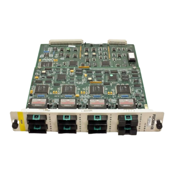
INTRODUCTION FDCMIM-04 FDCMIM-24 FDDI Figure 1-1. FDCMIM-04 / 24 / 34 / 44 FDDI Concentrator 1.2 OVERVIEW The FDCMIM is a concentrator module that resides in an MMAC network hub containing a Flexible Network Bus (FNB). The FDCMIM acts as a modular component in a Dual Attached Concentrator. - Page 9 FDCMIM-08 FDDI Figure 1-2. FDCMIM-08 / 28 / 38 / 48 FDDI Concentrator By using an FDMMIM, FDMMIM-04, FDMMIM-24, or FDMMIM-30 you can manage adjacent FDCMIMs through FDMMIM Local Management, the out-of-band management facility resident on the FDMMIM and FDMMIM-04 modules. You can also manage FDCMIMs with Cabletron Systems SNMP management tools such as ®...
-
Page 10: Getting Help
Cabletron Systems Technical Support. Before calling, please have the following information ready: • The product type (e.g., FDCMIM-24 or FDCMIM-38) • The product serial number. Note: Locate the serial number on the FDCMIM front panel. -
Page 11: Chapter 2 Configuration And Installation
CONFIGURATION AND INSTALLATION This chapter lists MMAC configuration guidelines, explains how to configure the FDCMIM in a hub that also holds Ethernet or Token Ring MIMs, and then explains how to install the FDCMIM as a stand- alone concentrator in an FDDI hub. 2.1 INSTALLATION REQUIREMENTS Before you start the installation, decide how you want to configure the MMAC. - Page 12 CONFIGURATION AND INSTALLATION To better explain how to configure your MMAC, refer to the following examples. Figure 2-1 illustrates how the combined load of two FDCMIMs exceeds the available power of an MMAC-3FNB. 11.8 amps FDCMIM-08 Figure 2-1. FDCMIMs in an MMAC-3FNB Figure 2-2 represents an MMAC-5FNB equipped with dual power supplies and three FDCMIMs.
-
Page 13: Mmac Configurations
11.8 amps 11.8 amps FDCMIM-08 FDCMIM-08 Figure 2-3. FDCMIMs in an MMAC-M8FNB When unsure of a hub’s ability to support a planned MIM configuration, check the appropriate manuals to determine the amount of power consumed by each MIM (amps at 5 Vdc), and then check your MMAC power supply configuration (single or multiple power supplies) to determine if you have sufficient power available to support the configuration. -
Page 14: Fdcmims Exclusively
CONFIGURATION AND INSTALLATION 2.3.1 FDCMIMs Exclusively By mixing FDCMIMs, you can create a stand-alone FDDI network of 4 to 56 nodes (7 FDCMIM-X8s in an MMAC-M8FNB = 56 master ports). Depending on MMAC shunting capabilities, you may have to install your FDCMIMs in adjacent slots to ensure continuity. -
Page 15: Irm3 And Ethernet Mims With Fdcmims
CONFIGURATION AND INSTALLATION 2.3.2 IRM3 and Ethernet MIMs with FDCMIMs This example uses the IRM3, but the same guidelines apply if you are using an IRM, IRM2, or IRBM. In Figure 2-4, the MMAC-5FNB has an IRM3 in slot 1, TPMIM-22s in slots 2 and 3, and FDCMIMs in slots 4 and 5. - Page 16 CONFIGURATION AND INSTALLATION POWER FAIL MMAC - 5PSM Figure 2-4. MMAC-5FNB with FDDI and Ethernet MIMs F N B Figure 2-5. MMAC Data Bus Structure Page 2-6 TPMIM-22 TPMIM-22 FDCMIM-04 FDCMIM-04 10BASE-T FDDI FDDI ETHERNET Ethernet “A” “B” “C” IRM3 RESET POWER FAIL...
-
Page 17: Trmm And Token Ring Mims With Fdcmims
Even though RMIMs can place Ethernet traffic on the bus that normally handles FDDI traffic, FDDI MIMs can still reside in the same hub with RMIMs. RMIMs determine whether or not the MIM that resides in the next higher numbered MMAC slot is an Ethernet MIM. -
Page 18: Twisted Pair Pinout Configuration
Medium Dependent (PMD) ports. Note: When connecting two twisted pair ports together (e.g., an M type port on an FDCMIM-24 to an F7069 Desktop Network Interface (DNI) card), a transmit and receive cross-over must occur between the two devices (i.e., within the cable). -
Page 19: Installing The Fdcmim
2.5 INSTALLING THE FDCMIM The FDCMIM has “hot swap” capabilities. This means you can insert and remove the module without first turning off the MMAC. Occasionally, depending on the MMAC configuration, other MIMs in the hub may go into a reset condition when you hot swap an FDCMIM. A reset condition can cause a momentary, but self correcting, interruption in network service. - Page 20 CONFIGURATION AND INSTALLATION 6. Once the module seats in the backplane, tighten the two knurled knobs. This step is important. If you do not tighten the knurled knobs, vibration can cause the module to lose contact with the backplane and disrupt your network. 7.
-
Page 21: Chapter 3 Using Lanview
LANVIEW is a visual diagnostic and status monitoring system developed by Cabletron Systems. LANVIEW LEDs can help you troubleshoot network problems such as open segments or FDCMIM power problems. The following sections describe FDCMIM LEDs. 3.1 FDCMIM STATUS LEDS The FDCMIM has two LEDs, PWR and FNB, that show MIM status. PWR (Power) When ON, this green LED indicates that the FDCMIM is getting power from the MMAC. -
Page 22: Port Status Leds
USING LANVIEW FNB (continued) Red or Flashing Red LED off 3.2 PORT STATUS LEDs Each FDCMIM port has two LEDs — PST and LNK. These LEDs show the port status. PST (Port Status) This multi-state LED can indicate the following: Green Amber Note: You must use an FDMMIM in conjunction with the FDCMIM to... - Page 23 USING LANVIEW LNK (Media Link OK) When ON, this green LED indicates that a connection exists between the FDCMIM and the node at the other end of the port cable segment. To ensure you maintain the link, the port generates an idle signal when not transmitting data.
-
Page 24: Chapter 4 Specifications
This chapter lists the operating specifications for the FDCMIM series modules. Cabletron Systems reserves the right to change these specifications at any time, without notice. Fiber Optic Interface Depending on the FDCMIM, interfaces have the following characteristics: Multimode Transmitter Optical wavelength: Optical output: Optical rise time: Optical fall time:... - Page 25 SPECIFICATIONS Multimode Receiver (Signal Detect) Assert power: Assert time: Deassert power: Deassert time: Hysteresis: Unshielded Twisted Pair Transmitter Amplitude: Rise time: Fall time: Rise/Fall variation: Overshoot: Droop (14 symbols): Unshielded Twisted Pair Receiver (Signal Detect) Assert Time: Deassert time: Page 4-2 -33.0 dBm typical -31.0 dBm maximum 10 sec typical...
- Page 26 Shielded Twisted Pair Transmitter Amplitude: Rise time: Fall time: Rise/Fall variation: Overshoot: Droop (14 symbols): Shielded Twisted Pair Receiver (Signal Detect) Assert Time: Deassert time: Single Mode Transmitter Optical wavelength: Optical output: Optical rise time: Optical fall time: Spectral width: Supply current: SPECIFICATIONS 1.325 Vpk maximum...
- Page 27 SPECIFICATIONS Single Mode Receiver Optical wavelength: Optical input: Optical rise time: Optical fall time: Supply current: Single Mode Receiver (Signal Detect) Assert power: Assert time: Deassert power: Deassert time: Hysteresis: Page 4-4 1330 nm typical -31.0 dBm minimum -14.0 dBm maximum 5 nsec maximum 5 nsec maximum 115 mAmps maximum...
- Page 28 Cable Types The FDDI Physical Layer Medium Dependent (PMD), Twisted Pair Physical Layer Medium Dependent (TP-PMD), and Single Mode Fiber Physical Medium Dependent (SMF-PMD) ANSI standards define cable requirements as follows: Multimode Fiber: Core diameter: Cladding diameter: Cable attenuation: Unshielded / Shielded Twisted Pair: Cable / Connector —...
- Page 29 SPECIFICATIONS Twisted Pair Cable Length The TP-PMD FDDI standard specifies the following: Maximum total cable length: Maximum twisted pair cable length between adjacent nodes: Single Mode Fiber Optic Cable Length The SMF-PMD FDDI standard specifies the following: Maximum total cable length: Single mode cable length between adjacent nodes: Power Requirements...
- Page 30 Use the following power consumption numbers when determining if a particular MMAC has enough power to support your configuration. FDCMIM-04 (SN 0568): FDCMIM-04 (all others): FDCMIM-08 (SN 0569): FDCMIM-08 (all others): FDCMIM-24: FDCMIM-28: FDCMIM-34: FDCMIM-38: FDCMIM-44: FDCMIM-48: Note: When calculating the total heat output of an MMAC hub, we...
Need help?
Do you have a question about the FDCMIM-24 and is the answer not in the manual?
Questions and answers